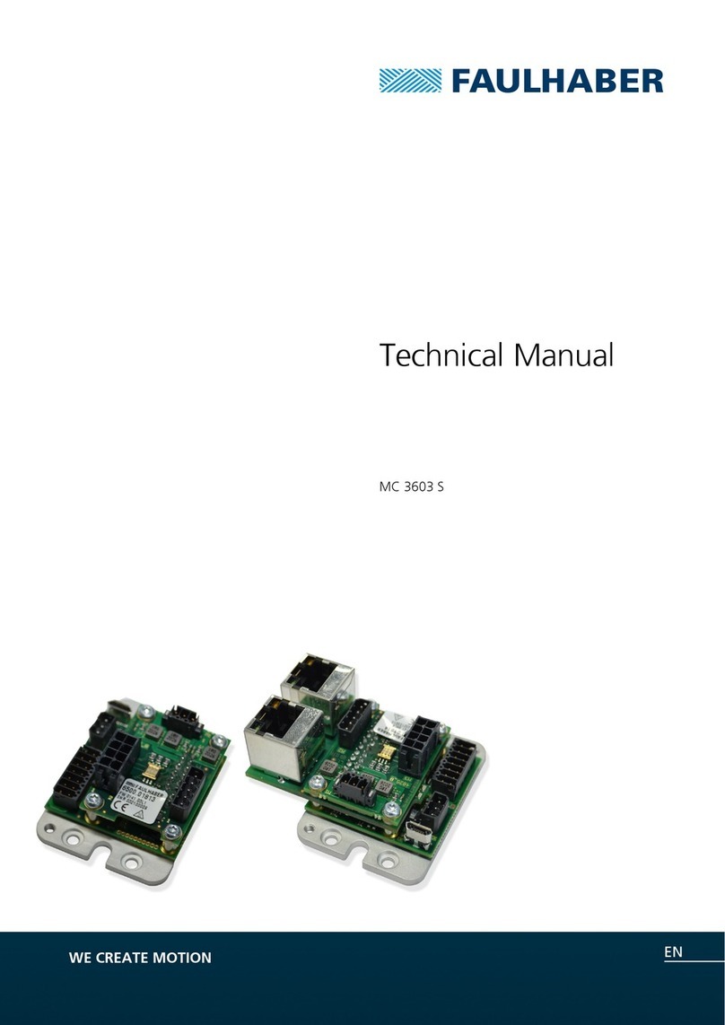
Faulhaber 3564K024B CS User manual

WE CREATE MOTION
Instruction Manual
EN
Motion Control Systems
Series 3564K024B CS
Motion Controller
Series MCBL 3003/06 S
Series MCDC 3003/06 S
RS232
dff_090277_bedienanleitung_sw.indd 3 25.03.2009 13:34:19 Uhr


3
Version:
4th edition, 03.04.2009
Copyright
by Dr. Fritz Faulhaber GmbH & Co. KG
Daimlerstr. 23/ 25 · 71101 Schönaich
All rights reserved, including translation rights.
No part of this description may be duplicated, reproduced,
stored in an information system or processed or transferred
in any other form without prior express written permission
of Dr. Fritz Faulhaber GmbH & Co. KG.
This instruction manual has been prepared with care.
Dr. Fritz Faulhaber GmbH & Co. KG cannot accept any li-
ability for any errors in this instruction manual or for the
consequences of such errors. Equally, no liability can be ac-
cepted for direct or consequential damages resulting from
improper use of the equipment.
The pertinent regulations regarding
safety engineering and interference suppression as well as
the specifications in this instruction manual must be com-
plied with when using the equipment.
Subject to modifications.
The current version of this instruction manual is available
on FAULHABER’s internet site:
www.faulhaber.com
Imprint

4
Table of Contents
1 Important Information 6
1.1 Symbols used in this instruction manual 6
1.2 Safety instructions 7
2 Description 8
2.1 General product description, motor 3564K024B CS 8
2.2 General product description, Motion Controller 9
2.3 Quick start 11
2.3.1 Operation via FAULHABER Motion Manager 11
2.3.2 Operation via own host application 13
3 Installation 14
3.1 Assembly 14
3.2 EMC compatible installation 15
3.2.1 Description of the EMC measures 15
3.3 Connector pin assignment 16
3.3.1 3564K024B CS 16
3.3.2 MCBL 3003/06 S 16
3.3.3 MCDC 3003/06 S 17
3.4 RS232 wiring 19
3.5 Motor wiring 20
3.6 Baud rate and node number 21
3.7 Basic settings 24
3.8 Compatibility mode 25
4 Functional description 26
4.1 Position control 27
4.2 Velocity control 29
4.2.1 Velocity presetting via RS232 29
4.2.2 Analog velocity presetting 30
4.3 Homing and limit switches 32
4.4 Enhanced operating modes 35
4.4.1 Stepper motor mode 35
4.4.2 Gearing mode (electronic gear) 36
4.4.3 Analog positioning mode 37
4.4.4 External encoder as actual value (not MCDC) 38
4.4.5 Voltage regulator mode 39
4.4.6 Analog target current presetting 39
4.4.7 IxR control for DC controllers 39
4.5 Special functions of the error connection 40
4.6 Sequence programs 42
4.7 Trace function 51
4.8 Technical information 53
4.8.1 Sinus commutation 53
4.8.2 Current regulator and I2t current limitation 53
4.8.3 Overtemperature protection 54
4.8.4 Under-voltage monitoring 54
4.8.5 Overvoltage regulation 55
4.8.6 Adjustment of the controller parameters 55

5
Table of Contents
5 Parameter description 57
5.1 Basic setting commands 58
5.1.1 Commands for special operating modes 58
5.1.2 Parameters for basic setting 58
5.1.3 General parameters 59
5.1.4 Configuration of fault pin and digital inputs 60
5.1.5 Configuration of homing and limit switches in 60
5.2 Query commands for basic setting 61
5.2.1 Operating modes and general parameters 61
5.2.2 Configuration of fault pin and digital inputs 65
5.2.3 Configuration of homing 65
5.3 Miscellaneous commands 66
5.4 Motion control commands 67
5.5 General query commands 68
5.6 Commands for sequence programs 69
5.7 Configuration at delivery 71
6 Operation 73
6.1 Commissioning 73
7 Maintenance 74
7.1 Service / Maintenance 74
7.2 Troubleshooting 74
8 Technical Data 75
8.1 Motor 3564K024B CS 75
8.1.1 Operating data 75
8.1.2 Product dimensions 76
8.1.3 Connection information 76
8.2 Motion Controller MCBL 3003 / 06 S 77
8.2.1 Operating data 77
8.2.2 Product dimensions 77
8.2.3 Connection information 78
8.3 Motion Controller MCDC 3003 / 06 S 80
8.3.1 Operating data 80
8.3.2 Product dimensions 80
8.2.3 Connection information 81
9 EMC 83
9.1 EC Directives 83
9.2 Electromagnetic compatibility (EMC) 84
9.3 EC Declaration of Conformity 86
10 Manufacturer's Declaration 87
11 Warranty 88
12 Command overview 89

6
Warning!
This pictogram with the wording "Warning!" indicates an imminent danger which can result in
physical injuries.
This arrow points out the appropriate action to take to prevent the imminent danger.
Caution!
This pictogram with the wording "Caution!" indicates an imminent danger which can result in slight
physical injuries or material damage.
This arrow points out the appropriate precautions.
Regulations, guidelines and directives
This pictogram with the wording "Regulation" indicates a statutory regulation, guideline or direc-
tive which must be observed in the respective context of the text.
Note
This "Note" pictogram provides tips and recommendations for use and handling of the component.
1 Important Information
1.1 Symbols used in this instruction manual
This instruction manual describes the handling and technical features of the following FAULHABER
equipment:
3564K024B CS
The 3564K024B CS integrates a brushless DC-Servomotor with a high-resolution encoder to deter-
mine actual position and a motion controller in one complete drive unit.
MCBL 3003/06 S
The MCBL 3003/06 S is an external motion controller for brushless DC servomotors with linear Hall
sensors, which can be operated without additional encoders.
MCDC 3003/06 S
The MCDC 3003/06 S is an external motion controller that is designed for the entire range of
FAULHABER DC micro motors.
Please read the complete instruction manual before using the controller.
Keep this instruction manual in a safe place for later use.
The information given in this instruction manual refers to the standard versions of the respective
equipment. Please refer to any additional information sheet provided in the event of differences in
information due to a customer-specific modification.
WARNING!
CAUTION!
REGULATION
NOTE

7
1 Important Information
Observance of the following safety instructions is prerequisite for trouble-free and safe operation
of the motor and the Motion Controller. Therefore, please carefully read through all the notes and
follow them when using the controllers.
Intended use
FAULHABER Motion Controllers are designed for the control of DC and BL motors. They have numer-
ous functions and operating modes which enable flexible adjustment to the respective drive function.
Thanks to the compact design, the units can be integrated into diverse applications with minimal
wiring. The flexible connection options open up a broad field of application in all areas, for example
in decentralized automation technology systems, as well as in handling devices and machine tools.
The Motion Controller's control parameters can be individually adjusted to the respective applica-
tion via a PC. The "FAULHABER Motion Manager" PC software for Microsoft Windows is available
for commissioning and configuration of the Motion Controller and can be downloaded free of
charge from the FAULHABER Homepage www.faulhaber.com .
Subject to compliance with the conditions described in Chapter 9 "EMC", the Motion Controllers
fulfil the relevant EMC Directives. Any effects as well as the specific relevant national regulations
must be taken into account when using the motor.
The Motion Controllers contain electronic components and are to be treated according to the ESD
regulations.
The Motion Controllers may not be used in environments where contact with water, chemicals
and / or dust is possible or in potentially explosive atmospheres.
Please ask the manufacturer for information about individual use under special ambient
conditions.
1.2 Safety instructions

8
2 Description
2.1 General product description, motor 3564K024B CS
The 3564K024B CS combines an electronically commutated DC-Servomotor, a high-resolution en-
coder to determine actual position and a programmable position and speed controller, based on a
high capacity digital signal processor (DSP), within a complete drive unit.
1
2
3
4
5
6
1 Heat sink / Cover
2 Housing
3 Motor
4 Mounting flange
5 Motor shaft
6 Connection cable
The motor is designed for the following drive functions:
Velocity control from 5 to 12 000 rpm with superior performance specifications in respect of
synchronous operation and minimal torque fluctuations. A PI controller ensures observance of the
target velocities.
Velocity profiles such as ramp, triangular or trapezoidal movements can be realised. Gentle start-
ing or deceleration can easily be implemented.
Positioning mode: Positioning with a resolution of 1/3000 revolutions.
Acquisition of reference marks and end position switches.
Enhanced operating modes: Stepper motor mode, analog positioning mode, voltage controller,
electronic gear, operation with external incremental encoder.
Torque control via adjustable current limitation.
Storage of the set configurations.
Storage and execution of sequence programs.
Various inputs and outputs are available for implementation of these functions:
Set value input for target velocity. Analog or PWM signal can be used. The input can also be used
as digital or reference input. A frequency signal or an external incremental encoder can also be
connected here.
Error output (Open Collector). Can also be reprogrammed as rotational direction, digital or refer-
ence mark input, and as pulse or digital output.
1 additional digital input.
RS232 interface for connection to PC or control with transfer rates of up to 115 kBaud. An exten-
sive ASCII command set is available for programming and operation.
RS232 interface
The drive can also be operated independently of the RS232 interface if the desired function, such as
velocity or position controller, has been previously programmed via analog input, stepper motor or
electronic gear.
NOTE

9
2 Description
2.1 General product description, motor 3564K024B CS
Options
Separate power supply for the motor and control electronics is possible as an ex-factory option (im-
portant for safety-relevant applications). In this case the 3rd input is not required. Special precon-
figuration of modes and parameters is possible on request.
The Motion Manager software can be downloaded free of charge from www.faulhaber.com.
2.2 General product description, Motion Controller
1
4
2
3
1 Mounting threads
2 Screw-type terminal strip, motor end
3 D-Sub connector for serial connection
4 Screw-type terminal strip, supply end
All of the Motion Controllers are based on a high performance digital signal processor (DSP), which
enables a high control quality, precise positioning and very low speeds.
The Motion Controllers are designed for the following functions:
Velocity control with high requirements on synchronous operation and minimal torque fluctua-
tions. A PI controller ensures observance of the target velocities.
Velocity profiles such as ramp, triangular or trapezoidal movements can be realised. Gentle start-
ing or deceleration can easily be implemented.
Positioning mode: Starting from defined positions with high resolution (1/3000 revolutions using
linear Hall sensors of BL motors).
Acquisition of reference marks and end position switches.
Enhanced operating modes: Stepper motor mode, analog positioning mode, voltage controller,
electronic gear, operation with external incremental encoder. MCDC 3003/06 S: IxR control.
Torque control via adjustable current limitation.
Storage of the set configurations.
Storage and execution of sequence programs.

10
2 Description
2.2 General product description, Motion Controller
Various inputs and outputs are available for implementation of these functions:
Set value input for target velocity. Analog or PWM signal can be used. The input can also be used
as digital or reference input. A frequency signal or an external incremental encoder can also be
connected here.
Error output (Open Collector). Can also be reprogrammed as rotational direction, digital or refer-
ence mark input, and as pulse or digital output.
1 to 3 additional digital inputs.
RS232 interface for connection to PC or control with transfer rates of up to 115 kBaud. An exten-
sive ASCII command set is available for programming and operation.
RS232 interface
The drive can also be operated independently of the RS232 interface if the desired function, such as
velocity or position controller, has been previously programmed via analog input, stepper motor or
electronic gear.
Options
Separate power supply for the motor and control electronics is possible as an ex-factory option (im-
portant for safety-relevant applications). In this case the 3rd input is not required. Special precon-
figuration of modes and parameters is possible on request.
The Motion Manager software can be downloaded free of charge from www.faulhaber.com.
NOTE

11
2 Description
2.3 Quick start
To facilitate introduction, this chapter highlights the initial steps for commissioning and operation
of FAULHABER Motion Controllers with serial interface. However, the detailed documentation must
always be read and adhered to, particularly chapter 3.7 "Basic settings"!
The units are delivered as standard without a valid node address (NODEADR0) and with a transfer
rate of 9600 baud. The settings can be changed via the interface, e.g. with the FAULHABER Motion
Manager.
If the FAULHABER Motion Manager is to be used to change the connection parameters, proceed as
follows:
1. Connect drive unit to a serial interface of the PC (e.g. COM1) via null modem cable and switch on.
2. Start FAULHABER Motion Manager.
3. Activate serial interface as communication interface and configure via the menu item “Terminal –
Connections…”.
4. Select menu item “Configuration – Connection parameters…”.
5. Set desired transfer rate and node address.
6. Press “Send” button.
7. The settings are transferred to the controller. The Motion Manager then adjusts to the same
baud rate and recalls the Scan function. The node should now be displayed with the correct node
number in Node Explorer.
8. If the settings are to be permanently stored, the “EEPSAV” button must then be pressed. After
switching off and on again, the drive will operate with the set configuration.
2.3.1 Operation via FAULHABER Motion Manager
The FAULHABER Motion Manager offers easy access to the Motion Controller’s command set. The
desired node must have been activated beforehand by double clicking in Node Explorer in the case
of network operation.
The FAULHABER commands described below can be entered directly in the command input line or
selected from the Commands menu.
In order to drive a motor via the Motion Manager, follow the procedure below (assuming a match-
ing baud rate):
1. Configure drive functions:
A user-friendly dialog that enables the desired settings to be made is available under the menu
item “Configuration – Drive functions…”.

12
2 Description
2.3 Quick start
Check basic settings
Incorrect values in the Motion Controller's settings can result in damage to the controller and / or
drive.
For external Motion Controllers MCBL 3003/06 S and MCDC 3003/06 S, you must check that the cor-
rect basic settings have been made for the connected motor (see chapter 3.7 "Basic settings").
For brushless motors, the correct motor type must be set, for DC motors the correct pulse number
must be specified for the encoder (ENCRES) under “Drive parameters”.
For operating the drive via the PC, the set value presetting must be set to digital (SOR0).
If the settings are to be permanently stored, press the “EEPSAV” button.
2. Activate drive:
“EN” command.
Enter in command input field and press “Send” button or select in “Commands – Motion control
– Enable drive” menu and press “Send” button.
3. Operate motor (examples):
Drive motor with 100 rpm velocity control:
“V100” command.
Enter in command input field and press “Send” button or select in “Commands – Motion
control – Initiate velocity mode” menu, enter value 100 in dialogue box, press OK and “Send”
button.
Stop motor:
“V0” command:
Move motor relatively by 10000 increments:
“LR10000” command to load the relative target position, “M” command to move to loaded
target position.
CAUTION!

13
2.3.2 Operation via own host application
Set your host application to the controller transfer rate (default 9600 baud) with the following con-
figuration:
8 data bits
1 stop bit
No Parity
The Xon/Xoff protocol must be used for rapid command sequences or transfer of sequence programs
and parameter sets.
An extensive set of ASCII commands is available for operating the FAULHABER Motion Controllers.
The ASCII commands have the following structure:
[Node No.] Command [Argument] CR
The node number is optional and is only required if several drives are being operated on one inter-
face. The command consists of a letter character string. The optional argument consists of an ASCII
numeric value. The end is always a CR character (Carriage Return, ASCII decimal code 13). Space
characters are ignored, and no distinction is made between upper and lower case.
The response to query commands or asynchronous events is also an ASCII character string, followed
by a CR character (Carriage Return, ASCII decimal code 13) and an LF character (Line Feed, ASCII
decimal code 10).
Example:
Actual position queries:
Transmit: POS[CR]
Receive: 98956[CR][LF]
Drive motor at 500 rpm:
Transmit: V500[CR]
If ANSW2 is set, you will receive an “OK” when the command has been successfully executed. If an
execution error occurred you will receive one of the following character strings:
“Unknown command”
“Invalid parameter”
“Command not available”
“Overtemperature – drive disabled”
Example:
Transmit: V500[CR]
Receive: OK[CR][LF]
The EEPSAV command always responds with the character string “EEPROM writing done” after suc-
cessful saving of the current settings in the data Flash memory, or with “Flash defect”, if the save
has failed.
All commands are listed in Chapter 5 "Parameter Description".
2 Description
2.3 Quick start

14
3 Installation
3.1 Assembly
The place of installation must be selected so that clean and dry cooling air is available for cooling
the unit. The units are intended for indoor operation. Large amounts of dust and high concentra-
tions of chemical pollutants must be avoided.
Cooling of the unit must be guaranteed, especially when installing in housings and cabinets. As the
unit operates with surface cooling, temperatures of up to 85 °C can occur. Perfect functioning is only
guaranteed if the supply voltage lies within the defined tolerance ranges.
Wiring work may only be carried out on terminal strips and connections if the units are voltage-free.
Please also note the additional instructions on installation in Chapter 9 "EMC".
Risk of damage
Incorrect assembly or assembly with the wrong fixing materials can cause damage to the Motion
Controller.
Observe the following assembly instructions.
Specialised staff
Only trained specialised staff and instructed persons with knowledge in the field of automation
technology and standards and regulations such as EMC Directive, Low Voltage Directive, Machinery
Directive, VDE Regulations (such as DIN VDE 0100, DIN VDE 0113/ EN 0204, DIN VDE 0160/EN 50178),
Accident Prevention Regulations may install and commission the units. This description must be
carefully read and heeded prior to commissioning.
Off load
The Motion Controller must be disconnected from the power supply for all types of assembly and
connection work.
Surface
Motion Controllers may be screwed onto flat, hard surfaces only.
Screw-type terminal strips
The maximum tightening torque of the screw-type terminal strips must be noted and observed. See
Chapter 8 "Technical Data".
CAUTION!

15
3 Installation
3.2 EMC compatible installation
Length of the connection leads
The maximum length of the connection leads is limited.
None of the connection leads, with the exception of the power supply, may exceed a length of 3 m.
Optimisation of performance with respect to emission and immunity requires the additional EMC
measures:
Ensuring allowable emissions or necessary immunity in the industrial sector may require the use
of an EMC filter and / or an EMC suppressor circuit.
Motion Controller Use environment Interference type Action
MCDC 3006 S Industrial sector Emission EMC filter
MCBL 3006 S Industrial sector Emission EMC filter
MCBL 3006 S Industrial sector Immunity EMC suppressor circuit
This table shows which additional EMC measures can be implemented to optimise the behaviour of
the equipment in the intended environment with regard to emission and immunity.
The devices are intended for use in the industrial sector only. If the devices are used in the home, in
business or in commerce or in a small business, appropriate measures must be taken to ensure that
the emitted interference is below the permitted limits!
3.2.1 Description of the EMC measures
The EMC filter (for MCDC 3006S and MCBL 3006S only)
The electronics and motor supply cables must be laid directly on the unit, each with two windings
through a suitable ferrite sleeve (e.g. Würth Elektronik No.: 74270090).
The EMC suppressor circuit (for MCBL 3006S only)
The signal cables of the MCBL 3006S must be laid directly on the unit with two windings through a
star ring (e.g. Würth Elektronik No.: 7427153).
CAUTION!

16
3 Installation
3.3 Connector pin assignment
Depending on their type, Motion Controllers are equipped with either screw-type terminal strips or
pin headers as connection options. The 3564K024B CS motor is equipped with an eight-core connec-
tion cable (AWG 24).
Electronic damage / ESD protection
Electrostatic discharges at the Motion Controller's connections can cause destruction of the
electronics.
Note and follow the ESD protective measures.
Incorrect connection of the cores can cause damage to or destruction of the electronics.
Connect the connections in accordance with the connector pin assignment, see table.
Please also note the additional instructions on installation in Chapter 9 "EMC".
Power supply connections (+24 V, GND)
Malfunctions can occur if an inadequately dimensioned power pack is used. If the supply leads are
incorrectly connected (polarity reversal) the internal fuse trips. This must be replaced in the factory!
The power pack should be adequately dimensioned for the connected motor.
Be sure to connect motor supply terminals to the correct polarity.
3.3.1 3564K024B CS
The connections are executed as coloured stranded wires and assigned as follows:
Wires Designation Meaning
blue GND GND
pink +24 V +24 V
brown AnIn Analog input
white Fault Error output
grey AGND Analog GND
yellow RxD RS232 RxD
green TxD RS232 TxD
red 3.In 3rd input
optional electronic supply UB
3.3.2 MCBL 3003/06 S
The connections are indicated on the terminal strips and are assigned as follows:
Connector pin assignment, supply end
Connection Designation Meaning
1 TxD RS232 TxD
2 RxD RS232 RxD
3 AGND Analog GND
4 Fault Error output
5 AnIn Analog input
6 +24 V +24 V
7 GND GND
8 3. In 3rd input
optional electronic supply UB
CAUTION!
CAUTION!

17
Connector pin assignment, motor end
Connection Designation Wire colour Meaning
1 Ph A brown Motor phase A
2 Ph B orange Motor phase B
3 Hall C grey Hall sensor C
4 Hall B blue Hall sensor B
5 SGND black Signal GND
6 +5 V red VCC
7 Hall A green Hall sensor A
8 PH C yellow Motor phase C
In addition, a 9-pin SUB-D connector is attached, with the following assignment:
Pin Meaning
2 RxD
3 TxD
5 GND
3.3.3 MCDC 3003/06 S
The connections are indicated on the terminal strips and are assigned as follows:
Connector pin assignment, supply end
Connection Designation Meaning
1 TxD RS232 TxD
2 RxD RS232 RxD
3 AGND Analog GND
4 Fault Error output
5 AnIn Analog input
6 +24 V +24 V
7 GND GND
8 3. In 3. input
optional electronic supply UB
Connector pin assignment, motor end
Connection Designation Meaning
1 Mot - Motor -
2 Mot + Motor +
3 SGND Encoder GND
4 +5 V Encoder VCC
5 Ch B Encoder channel B
6 Ch A Encoder channel A
7 4. In 4th input
8 5. In 5th input
In addition, a 9-pin SUB-D connector is attached, with the following assignment:
Pin Meaning
2 RxD
3 TxD
5 GND
3 Installation
3.3 Connector pin assignment

18
3 Installation
3.3 Connector pin assignment
Analog input (analog input, analog GND = AGND)
The analog input is executed as a differential input. The analog GND should be connected to the
power supply GND. This prevents the voltage drop in the supply cable from affecting the target
velocity value.
The analog input has various uses, depending on the configuration:
Presetting of target velocity value via analog voltage
Presetting of target velocity value via PWM signal
Current limitation value via analog voltage
Presetting of target position via analog voltage
Digital input for reference and limit switches
Connection for an external encoder (Analog input to GND: Channel A / Analog GND to GND:
Channel B) in gearing or BL encoder mode.
RS232 connections
The RS232 wiring is established via the connections RxD, TxD and the supply GND. The integrated
RS232 interface allows direct connection with a PC with use of a null modem cable, in which the
transmit cable (TxD) and the receive cable (RxD) are crossed.
Error output
The error output is characterised by the following characteristics:
Switch that switches to GND (Open Collector)
Output resistor in open state (High Level): 100 k
The switch is open in the event of error (High Level)
Output current limited to approx. 30 mA, voltage in open state must not exceed the power supply
(maximum UB)
Short-circuit proof
The error output is activated in the following situations:
Current limitation active
Over-voltage controller active (power supply over 32 V)
Power stage switched off due to excessive temperature
The error output connection can also be reconfigured for other functions:
Pulse output (only MCBL, 3564…B CS)
Digital output
Limit switch input
Rotational direction input

19
3 Installation
3.3 Connector pin assignment
3th input
This connection can be used as reference or digital input. The drive can also be optionally provided
with separate electronics supply at this connection ex-works, enabling the motor voltage to be
switched off independently of the electronics supply.
4th / 5th input (MCDC only)
These inputs can be used as digital and reference inputs.
3.4 RS232 wiring
Use a null modem cable in which the transmit cable (TxD) and the receive cable (RxD) are crossed, in
order to connect the controller with the PC or control.
Wiring with one Motion Controller – command NET0
1 2 3 4 5
9876
1 2 3 4 5
9876
1 2 3 4 5
9876
GND
TxD
RxD
GND
TxD
RxD
GND
TxD
RxD
PC Motion Controller nMotion Controller 1
1 2 3 4 5
9876
1 2 3 4 5
9876
GND
TxD
RxD
GND
TxD
RxD
PC Motion Controller 1
GND
4,7
1 2 3 4 5
9876
1 2 3 4 5
9876
1 2 3 4 5
9876
GND
TxD
RxD
GND
TxD
RxD
GND
TxD
RxD
PC Motion Controller nMotion Controller 1
1 2 3 4 5
9876
1 2 3 4 5
9876
GND
TxD
RxD
GND
TxD
RxD
PC Motion Controller 1
GND
4,7
Wiring with several Motion Controllers – command NET1

20
3.5 Motor wiring
3 Installation
MCDC 3003/06 S; MCBL 3003/06 S:
The encoder and signal lines are susceptible to interference, which makes it impossible to specify a
maximum cable length.
Shielded wires must always be used with cable lengths > 300 mm.
It must be generally noted that the lines between the Motion Controller and the motor must be
kept as short as possible, since drive system properties such as quietness and concentric running
deteriorate as the length of the line increases.
MCDC 3003/06 S only:
The use of an encoder with complementary output (e.g. line driver) increases interference immunity.
A HEDL adapter no. 6501.00064 from FAULHABER must be used in this case.
MCBL motor wiring
Ph A
Ph B
Ph C
Housing
SGND
+ 5 V
Hall A
Hall B
Hall C
Housing
Phase A
Phase B
Phase C
Hall sensor A
Hall sensor B
Hall sensor C
Mot –
Mot +
Housing
SGND
+ 5 V
CH A
CH B
Housing
Brushless
DC Servomotor
DC-Motor
MCDC motor wiring
Ph A
Ph B
Ph C
Housing
SGND
+ 5 V
Hall A
Hall B
Hall C
Housing
Phase A
Phase B
Phase C
Hall sensor A
Hall sensor B
Hall sensor C
Mot –
Mot +
Housing
SGND
+ 5 V
CH A
CH B
Housing
Brushless
DC Servomotor
DC-Motor
This manual suits for next models
5
Table of contents
Other Faulhaber Control System manuals
Popular Control System manuals by other brands
ZKTeco
ZKTeco CMP-100A user manual
ProMinent
ProMinent DULCOMARIN 3 Compact Assembly and operating instructions

Emerson
Emerson PACSystems user guide
Siemens
Siemens SIMATIC manual
Intellitec
Intellitec 50 Amp Smart EMS 900 Installation & service manual

TLS Electronics
TLS Electronics QuickControl XL Installation and user manual

EMX Industries, Inc.
EMX Industries, Inc. BG-FE operating instructions

Daintree
Daintree GE current LightGrid Node installation guide

De Haardt
De Haardt XTRA.BLACK BOX user manual
HERA
HERA ZigBee Assembly and operating instructions
OSF
OSF Alarm-control.plus Installation and operation manual
fadini
fadini BARRI 88 instruction manual
