Faulhaber MC 3603 S User manual

WE CREATE MOTION
Technical Manual
MC 3603 S
EN

Imprint
2
Version:
1st edition, 20.04.2021
Copyright
by Dr. Fritz Faulhaber GmbH & Co. KG
Daimlerstr. 23 / 25 · 71101 Schönaich
All rights reserved, including those to the translation.
No part of this description may be duplicated, reproduced,
stored in an information system or processed or
transferred in any other form without prior express written
permission of Dr. Fritz Faulhaber GmbH & Co. KG.
This document has been prepared with care.
Dr. Fritz Faulhaber GmbH & Co. KG cannot accept any
liability for any errors in this document or for the
consequences of such errors. Equally, no liability can be
accepted for direct or consequential damages resulting
from improper use of the equipment.
The relevant regulations regarding safety engineering
and interference suppression as well as the requirements
specified in this document are to be noted and followed
when using the software.
Subject to change without notice.
The respective current version of this technical manual is
available on FAULHABER's internet site:
www.faulhaber.com
1st edition, 20.04.2021 7000.05072, 1st edition, 20.04.20217000.05072

1st edition, 20.04.2021 7000.05072, 1st edition, 20.04.20217000.05072
Content
3
1 About this document ....................................................................................................... 5
1.1 Validity of this document ...................................................................................... 5
1.2 Associated documents ............................................................................................ 5
1.3 Using this document .............................................................................................. 5
1.4 List of abbreviations ............................................................................................... 6
1.5 Symbols and designations ...................................................................................... 7
2 Safety ................................................................................................................................ 8
2.1 Intended use ........................................................................................................... 8
2.2 Safety instructions .................................................................................................. 9
2.2.1 Dangers in the event of damages and changes.................................... 9
2.2.2 Correct installation and commissioning ................................................ 9
2.2.3 Heat development ................................................................................ 10
2.3 Environmental conditions .................................................................................... 10
2.4 EC directives on product safety ........................................................................... 11
3 Product description ........................................................................................................ 12
3.1 General product description ................................................................................ 12
3.2 Product information ............................................................................................. 13
3.3 Product variants .................................................................................................... 13
3.3.1 MC 3603 S RS/CO ................................................................................... 14
3.3.1.1 MC 3603 S RS/CO connector pin assignment........................ 15
3.3.1.2 Connection option 6889 for DC-motors with encoders
IE2, IEH2, IEH3, IEH3 L ............................................................ 21
3.3.1.3 Connection option 6890 for DC-motors with encoders
IE3, IE3 L ................................................................................. 26
3.3.2 MC 3603 S ET ......................................................................................... 30
3.3.2.1 Connector pin assignment of MC 3603 S ET extended
version .................................................................................... 32
3.3.2.2 Connection option 6889 for DC-motors with encoders
IE2, IEH2, IEH3, IEH3 L............................................................ 39
3.3.2.3 Connection option 6890 for DC-motors with encoders
IE3, IE3 L ................................................................................. 44
4 Installation ...................................................................................................................... 48
4.1 Mounting .............................................................................................................. 48
4.1.1 Mounting instructions .......................................................................... 48
4.1.2 Attachment via the side plates ............................................................ 49
4.1.3 Installation with top-hat rail clips........................................................ 50
4.2 Electrical connection ............................................................................................ 51
4.2.1 Notes on the electrical connection ...................................................... 51
4.2.2 Drive connections.................................................................................. 52
4.2.3 Connection of the power supply ......................................................... 53
4.2.3.1 Power supply.......................................................................... 53
4.2.4 I/O circuit diagrams ............................................................................... 54
4.2.5 External circuit diagrams ...................................................................... 55
4.3 Electromagnetic compatibility (EMC) .................................................................. 59
4.3.1 Considered systems ............................................................................... 59
4.3.2 Functional earthing .............................................................................. 61
4.3.3 Cable routing ........................................................................................ 62

1st edition, 20.04.2021 7000.05072, 1st edition, 20.04.20217000.05072
Content
4
4.3.4 Shielding................................................................................................ 63
4.3.4.1 Establishing the shield connection ....................................... 64
4.3.4.2 Establishing shield connection with cable lug ..................... 65
4.3.5 Sensor and encoder interfaces ............................................................. 66
4.3.5.1 Analog sensors and analog Hall sensors .............................. 67
4.3.5.2 Incremental encoders / Digital Hall sensors / Digital sensors 67
4.3.5.3 Encoders with absolute interface ......................................... 67
4.3.6 Using filters ........................................................................................... 67
4.3.6.1 Mounting arrangement (example: top-hat rail/DIN rail) .... 68
4.3.6.2 PWM filter (motor-side) ........................................................ 68
4.3.6.3 Emission-reducing, ferrite-based filters (motor side) .......... 68
4.3.6.4 Input-side filters..................................................................... 69
4.3.6.5 Insulation resistance .............................................................. 69
4.3.6.6 Coiling ferrite ring ................................................................. 69
4.3.7 Error avoidance and troubleshooting ................................................. 70
5 Maintenance and diagnostics ........................................................................................ 72
5.1 Maintenance instructions .................................................................................... 72
5.2 Maintenance tasks ................................................................................................ 72
5.3 Diagnosis ............................................................................................................... 72
5.4 Troubleshooting ................................................................................................... 73
6 Accessories ...................................................................................................................... 74
7 Warranty ......................................................................................................................... 75
8 Additional documents .................................................................................................... 76
8.1 Declaration of Conformity ................................................................................... 76
8.2 Declaration of Incorporation ............................................................................... 78

1st edition, 20.04.2021 7000.05072, 1st edition, 20.04.20217000.05072
About this document
5
1 About this document
1.1 Validity of this document
This document describes the installation and use of the FAULHABER MC 3603 S series.
This document is intended for use by trained experts authorised to perform installation and
electrical connection of the product.
All data in this document relate to the standard versions of the series listed above. Changes
relating to customer-specific versions can be found in the corresponding data sheet.
1.2 Associated documents
For certain actions during commissioning and operation of FAULHABER products additional
information from the following manuals is useful:
These manuals can be downloaded in pdf format from the web page
www.faulhaber.com/manuals.
1.3 Using this document
Read the document carefully before undertaking configuration, in particular chapter
“Safety”.
Retain the document throughout the entire working life of the product.
Keep the document accessible to the operating and, if necessary, maintenance person-
nel at all times.
Pass the document on to any subsequent owner or user of the product.
Manual Description
Motion Manager 6 Operating instructions for FAULHABER Motion Manager PC software
Quick start guide Description of the first steps for commissioning and operation of FAULHABER Motion
Controllers
Drive functions Description of the operating modes and functions of the drive
Accessories manual Description of the accessories

1st edition, 20.04.2021 7000.05072, 1st edition, 20.04.20217000.05072
About this document
6
1.4 List of abbreviations
Abbreviation Meaning
AC Alternating Current
AnIn Analog input
AGND Analog Ground
CAN_L CAN-Low
CAN_H CAN-High
CLK Clock
CS Chip Select
DigIn Digital input
DigOut Digital output
EFC Electronics Filter Conformity
EFM Electronics Filter Motor
EFS Electronics Filter Supply
EMC Electromagnetic compatibility
ESD Electrostatic discharge
ET EtherCAT (Ethernet for Control Automation Technology)
GND Ground
PLC Programmable Logic Controller
PWM Pulse Width Modulation
RxD Receive Data
TTL Transistor Transistor Logic
TxD Transmit data
NMT CANopen network management
RTR Remote Request
OD Object dictionary

1st edition, 20.04.2021 7000.05072, 1st edition, 20.04.20217000.05072
About this document
7
1.5 Symbols and designations
DANGER
DANGER
!
Danger with high level of risk: if not avoided, death or serious injury will result.
Measures for avoidance
WARNING
WARNING
!
Danger with medium level of risk: if not avoided, death or serious injury may result.
Measures for avoidance
CAUTION
CAUTION
!
Danger with low level of risk: if not avoided, minor or moderate injury may result.
Measures for avoidance
NOTICE
NOTICE
Risk of damage.
Measures for avoidance
Pre-requirement for a requested action
1. First step for a requested action
Result of a step
2. Second step of a requested action
Result of an action
Request for a single-step action
Instructions for understanding or optimizing the operational procedures

1st edition, 20.04.2021 7000.05072, 1st edition, 20.04.20217000.05072
Safety
8
2 Safety
2.1 Intended use
The Motion Controllers described here are designed for use for control and positioning
tasks for the following motors:
DC-motors
Linear DC-Servomotors
Brushless DC-motors
The Motion Controllers described here are designed for use as slaves for control and posi-
tioning tasks for the following motors:
DC-motors
Linear DC-Servomotors
Brushless DC-motors
The Motion Controller is suitable in particular for tasks in the following fields of applica-
tion:
Robotics
Toolbuilding
Automation technology
Industrial equipment and special machine building
Medical technology
Laboratory technology
When using the Motion Controllers the following aspects should be observed:
The Motion Controller contains electronic components and should be handled in
accordance with the ESD regulations.
Do not use the Motion Controller in environments where it will come into contact with
water, chemicals and/or dust, nor in explosion hazard areas.
The Motion Controller is not suitable for use in combination with stepper motors.
The Motion Controller should be operated only within the limits specified in the data
sheet.
Please ask the manufacturer for information about use under individual special
environmental conditions.

1st edition, 20.04.2021 7000.05072, 1st edition, 20.04.20217000.05072
Safety
9
2.2 Safety instructions
In addition to the safety risks described in this technical manual, machine-specific dangers
could arise that cannot be foreseen by the manufacturer of the Motion Controller (e.g., risk
of injury from driven components). The manufacturer of the machine in which the Motion
Controller is installed must perform a risk analysis in accordance with the regulations appli-
cable to the machine and inform the end user of the residual risks.
2.2.1 Dangers in the event of damages and changes
Damage to the Motion Controller can impair its functions. A damaged Motion Controller
can unexpectedly start, stop or jam. This can result in damage to other components and
materials.
Do not start up a drive system with a defective or damaged Motion Controller.
Appropriately mark a defective or damaged Motion Controller.
Do not replace defective or damaged components of the Motion Controller.
Make no changes (modifications, repairs) to the Motion Controller.
Have loose or defective connections immediately replaced by an electrician.
After replacing a defective or damaged Motion Controller, test and document the cor-
rect function.
2.2.2 Correct installation and commissioning
Errors during the installation and commissioning of the Motion Controller could impair its
function. An incorrectly installed Motion Controller can unexpectedly start, stop or jam.
This can result in damage to other components and materials.
Follow the instructions for installation and commissioning given in these installation
instructions exactly.
Only have work on electrical operating equipment performed by an electrician.
During all work on the electrical equipment, observe the 5 safety rules:
a) Disconnect from power
b) Secure against being switched on again
c) Check that no voltage is present
d) Ground and short-circuit
e) Cover or block-off adjacent parts that are under voltage
Electrostatic discharges can damage the electronics.
Store and transport the Motion Controller in suitable ESD packaging.
Handle the Motion Controller in compliance with the ESD handling regulations (e.g.
wear an ESD wristband, ground surrounding components).
During installation, ensure that components in the surroundings cannot be electrostat-
ically discharged.

1st edition, 20.04.2021 7000.05072, 1st edition, 20.04.20217000.05072
Safety
10
Soiling, foreign bodies, humidity and mechanical influences can damage the electronics.
Keep foreign objects away from the electronics.
Install the Motion Controller in a housing that protects it from mechanical influences
and is adapted to the ambient conditions (protection class determination).
Installation and connection work while supply voltage is applied at the device can damage
the electronics.
Do not insert or withdraw connectors while supply voltage is applied at the Motion
Controller.
During all aspects of installation and connection work on the Motion Controller, switch
off the power supply.
Incorrect connection of the pins can damage the electronic components.
Connect the wires as shown in the connection assignment.
2.2.3 Heat development
Active components may cause the Motion Controller to heat up. If touched, there is a risk of burn-
ing.
Protect the Motion Controller against being touched and cool sufficiently.
If necessary, affix a suitable warning sign in the immediate vicinity of the controller.
Fig. 1: Suitable warning sign acc. to DIN EN ISO 7010
2.3 Environmental conditions
Select the installation location so that clean dry air is available for cooling the Motion
Controller.
Select the installation location so that the air has unobstructed access to flow around
the drive.
When installed within housings and cabinets take particular care to ensure adequate
cooling of the Motion Controller through the base plate.
Select a power supply that is within the defined tolerance range.
Protect the Motion Controller against heavy deposits of dust, in particular metal dust
and chemical pollutants.
Protect the Motion Controller against humidity and wet.

1st edition, 20.04.2021 7000.05072, 1st edition, 20.04.20217000.05072
Safety
11
2.4 EC directives on product safety
The following EC directives on product safety must be observed.
If the Motion Controller is being used outside the EU, international, national and
regional directives must be also observed.
Machinery Directive (2006/42/EC)
The controllers with attached motor described in this technical manual may be drive sys-
tems according to the Machinery Directive. They are therefore to be considered incomplete
machines according to the Machinery Directive. Compliance is documented by the Declara-
tion of Incorporation for the product and by the EC Declaration of the Conformity.
EMC Directive (2014/30/EU)
The directive concerning electromagnetic compatibility (EMC) applies to all electrical and
electronic devices, installations and systems sold to an end user. In addition, CE marking can
be undertaken for built-in components according to the EMC Directive. Conformity with
the directive is documented in the Declaration of Conformity.
Applied standards
Various harmonised standards were applied to the products described in this technical
manual; these standards are documented in the EC Declaration of Conformity. You can find
the Declaration of Incorporation for the product and the EC Declaration of Conformity in
chap. 8, p. 76.

1st edition, 20.04.2021 7000.05072, 1st edition, 20.04.20217000.05072
Product description
12
3 Product description
3.1 General product description
The MC 3603 S products are unhoused versions of the FAULHABER Motion Controllers and
control either DC, LM or BL motors. The Motion Controllers are configured here via the
FAULHABER Motion Manager software V6 (version 6.8 and higher).
The drives can be operated in the network via the CANopen or EtherCAT fieldbus interface.
In smaller setups, networking can also be performed via the RS232 interface. The Motion
Controller operates in the network in principle as a slave; master functionality for actuating
other axes is not provided. After basic commissioning via Motion Manager, the controllers
can alternatively also be operated without communication interface.
The controllers are secured to a flat base plate via the mounting holes. With optional acces-
sories, mounting is also possible on a DIN rail.
The output stages are exchangeable and are matched to the various sizes and types of
motors, i.e. DC, BL and LM motors from 13 – 42 mm, as listed in the FAULHABER product
portfolio.
The following connections are available on the supply side:
Communications interfaces
Common or separate power supplies between motor and controller
Various inputs and outputs
The following connections are available on the motor side, depending on the product com-
bination:
Motor phases
Feedback components such as:
Digital/analog Hall sensors
Incremental encoders with or without line drivers.
Absolute encoder with BiSS-C or SSI interface.
Not all options of the BiSS-C interface are supported by FAULHABER Motion Control-
lers of the V3.0 series. Before using encoders from other manufacturers, clarify the
compatibility with FAULHABER Support.
Motion Controllers with RS232, CANopen or EtherCAT interface can also be operated
independently of the communications interface if a pre-programmed function or
sequence program has been programmed without digital command controls.
1st edition, 20.04.2021 7000.05072, 1st edition, 20.04.20217000.05072
Product description
13
3.2 Product information
Fig. 2: Designation key
3.3 Product variants
The unhoused variant of the Motion Controller is available in 2 versions.
MC 3603 S RS/CO, see chap. 3.3.1, p. 14
MC 3603 S ET, see chap. 3.3.2, p. 30
In addition to the standard variants, the Motion Controllers can be connected to other
encoder combinations by means of product options:
MC 3603 S RS/CO with connection option 6889 for DC-motors with encoders IE2, IEH2,
IEH3, IEH3L, see chap. 3.3.1.2, p. 21
MC 3603 S RS/CO with connection option 6890 for DC-motors with encoders IE3, IE3 L,
see chap. 3.3.1.3, p. 26
MC 3603 S ET with connection option 6889 for DC-motors with encoders IE2, IEH2, IEH3,
IEH3L, see chap. 3.3.2.2, p. 39
MC 3603 S ET with connection option 6890 for DC-motors with encoders IE3, IE3 L, see
chap. 3.3.2.3, p. 44
…
MC
RS:
CO:
S:
0:3
MC:
36:
36 S
ET:
03
Serial interface RS232
Interface CANopen
Interface EtherCAT
Controller with pin terminals
Max. continuous output current 3 A
Max. power supply 36 V
Motion Controller

1st edition, 20.04.2021 7000.05072, 1st edition, 20.04.20217000.05072
Product description
14
3.3.1 MC 3603 S RS/CO
The MC 3603 S RS/CO Motion Controllers can be addressed via either the RS232 interface or
via the CANopen interface. The USB interface is available in all devices.
Fig. 3: MC 3603 S RS/CO standard version
M2
M1
M3
S1
X1X2X3
1
1
2
1
S2
1
2
1
1
1C
2
3
O
N
Status
57
40 max. 26

1st edition, 20.04.2021 7000.05072, 1st edition, 20.04.20217000.05072
Product description
15
Tab. 1: Connector overview and DIP switch
Tab. 2: LED overview
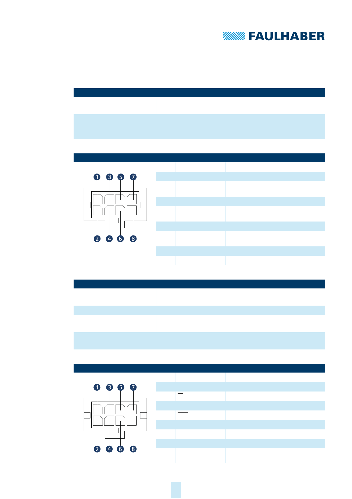
3.3.1.1 MC 3603 S RS/CO connector pin assignment
Motor connection (M1)
Tab. 3: Pin assignment of the BL motor connection (M1)
Tab. 4: Electrical data of the motor connection (M1)
Designation Function
M1 (motor) Connection of the motor phases
M2 (sensor) Connection of the Hall sensors
M3 (encoder) Connection of an incremental encoder with or without line driver. Alternatively an absolute
encoder can be connected with or without line driver.
X1 (USB) USB interface connection
X2 (COM) CAN/RS232 interface connection
X3 (I/O) Voltage supply of the controller and motor, inputs or outputs for external circuits
S1 (DIP switch
COM)
Selection of the COM interface:
C: CAN
Otherwise: RS232
S2 (DIP switch
Encoder Term)
Encoder terminal resistance:
Encoder with line driver: S2-1, S2-2 and S2-3 in ON position
Encoder without line driver: S2-1, S2-2 and S2-3 in OFF position
Designation Function
State LED Green (continuous light): Device active.
Green (flashing): Device active. However the state machine has not yet reached the Operation
Enabled state.
Red (continuously flashing): The drive has switched to a fault state. The output stage will be
switched off or has already been switched off.
Red (error code): Booting has failed. Please contact FAULHABER Support.
Pin Designation Meaning
1 Motor A Connection of motor, phase A
2Motor B Connection of motor, phase B
3 Motor C Connection of motor, phase C
Designation Value
Motor power supply 0...Umot
Max. 9 A
100 kHz

1st edition, 20.04.2021 7000.05072, 1st edition, 20.04.20217000.05072
Product description
16
Tab. 5: Pin assignment of the DC motor connection (M1)
Tab. 6: Electrical data of the DC motor connection (M1)
Sensor connection (M2)
Tab. 7: Pin assignment at sensor connection (M2) for 3 Hall sensor signals
Tab. 8: Pin assignment at sensor connection (M2) for sin/cos sensor
Only in combination with sin/cos sensors on FAULHABER LM motors or BX4 motors in sin/cos
special version.
Tab. 9: Electrical data of the sensor connection (M2)
Pin Designation Meaning
1 Motor + Connection of motor, positive pole
2Motor – Connection of the motor, negative pole
Designation Value
Motor power supply 0...Umot
Max. 9 A
100 kHz
Pin Designation Meaning
1U
DD Power supply for sensors
2GND Ground connection
3 Sens A Hall sensor A
4Sens B Hall sensor B
5 Sens C Hall sensor C
Pin Designation Meaning
1U
DD Power supply for sensors
2GND Ground connection
3 COS(+) Cosine signal
4SIN(+) Sine signal
5n.c. –
Designation Value
Sensor power supply 5 V
<100 mA
Sensor connection <5 V

1st edition, 20.04.2021 7000.05072, 1st edition, 20.04.20217000.05072
Product description
17
Encoder connection (M3)
The pin assignment of the encoder connector varies depending on the encoder type.
Incremental encoder with or without line driver
Absolute encoder with or without line driver.
The encoder model is selected in the configuration of the Motion Controller during com-
missioning.
With DIP switch S2, a 120 Ωterminating resistor can be activated for each signal.
Tab. 10: Pin assignment for incremental encoder with line driver (M3)
Tab. 11: Electrical data for incremental encoder with line driver (M3)
Tab. 12: Pin assignment for incremental encoder without line driver (M3)
Pin Designation Meaning
1U
DD Power supply for incremental encoder
2GND Ground connection
3ChannelA Encoder channel A (logically inverted sig-
nal)
4Channel A Encoder channel A
5ChannelB Encoder channel B (logically inverted sig-
nal)
6Channel B Encoder channel B
7Index Encoder index (logically inverted signal)
8Index Encoder index
Designation Value
Power supply for incremental
encoder
5V
<100 mA
Connection of the incremental
encoder
<5 V
<2 MHz
5kΩ
Pin Designation Meaning
1U
DD Power supply for incremental encoder
2GND Ground connection
3ChannelA n.c.
4Channel A Encoder channel A
5ChannelB n.c.
6Channel B Encoder channel B
7Index n.c.
8Index Encoder index
1st edition, 20.04.2021 7000.05072, 1st edition, 20.04.20217000.05072
Product description
18
Tab. 13: Electrical data for incremental encoder without line driver (M3)
Tab. 14: Pin assignment for absolute encoder with line driver (M3)
Tab. 15: Electrical data for absolute encoder with line driver (M3)
Tab. 16: Pin assignment for absolute encoder without line driver (M3)
Designation Value
Power supply for incremental
encoder
5V
<100 mA
Connection of the incremental
encoder
<5 V
<2 MHz
5kΩ
Pin Designation Meaning
1U
DD Power supply for absolute encoder
2GND Ground connection
3CS Chip Select for absolute encoder (logically
inverted signal)
4CS Chip Select for absolute encoder
5Data Data for absolute encoder (logically
inverted signal)
6Data Data for absolute encoder
7CLK Clock for absolute encoder (logically
inverted signal)
8CLK Clock for absolute encoder
Designation Value
Absolute encoder power supply 5 V
<100 mA
Connection Chip Select 5V
Connection data <5 V
5kΩ
Connection clock 5V
1MHz
Pin Designation Meaning
1U
DD Power supply for absolute encoder
2GND Ground connection
3CS n.c.
4CS Chip Select for AES
5Data n.c.
6Data Data for AES
7CLK n.c.
8CLK Clock for AES

1st edition, 20.04.2021 7000.05072, 1st edition, 20.04.20217000.05072
Product description
19
Tab. 17: Electrical data for absolute encoder without line driver (M3)
USB (X1)
Tab. 18: USB port
COM port (X2)
The pin assignment of the COM connection differs according to the type of communication.
The distinction is made between the following types of communication:
RS232
CANopen
The interface is selected with DIP switch S1.
Tab. 19: Pin assignment of the COM port (X2) for RS232
Tab. 20: Pin assignment of the COM port (X2) for CANopen
Designation Value
Absolute encoder power supply 5 V
<100 mA
Connection Chip Select 5V
Connection data <5 V
5kΩ
Connection clock 5V
1MHz
Designation Meaning
USB communication (USB micro B)
Pin Designation Meaning
1 TxD RS232 interface transmit direction
2RxD RS232 interface receive direction
3 GND Ground connection
Pin Designation Meaning
1 CAN-H CAN-High interface
2CAN-L CAN-Low interface
3 GND Ground connection

1st edition, 20.04.2021 7000.05072, 1st edition, 20.04.20217000.05072
Product description
20
I/O connection (X3)
Tab. 21: Pin assignment of the I/O connection (X3)
Tab. 22: Electrical data for the I/O connection (X3)
Pin Designation Meaning
1U
DD Power supply for external consumer loads
2GND Ground connection
3 DigOut 1 Digital output (open collector)
4DigOut 2 Digital output (open collector)
5 DigIn 1 Digital input
6DigIn 2 Digital input
7 DigIn 3 Digital input
8AnIn 1 Analog input
9 AnIn 2 Analog input
10 AGND Ground connection for analog inputs
11 UpPower supply of the electronics
12 GND Ground connection
13 Umot Power supply of the motor
14 GND Ground connection
Designation Value
Power supply for external consum-
ers
5V
<100 mA
DigOut low = GND
high = high resistance
27 kΩ
Max. 0.7 A
DigIn <30 V
27 kΩ
<1 MHz
TTL level: low < 0.5 V, high > 3.5 V a)
PLC level: low < 7 V, high > 11.5 V
a) The switching thresholds are set in the configuration of the Motion Controller during commissioning.
AnIn ±10 V
Reference potential: AGND
Power supply for controller 6…36 V
≤100 mA (without external consumer)
Motor power supply 6…36 V
1 3 5 7 9 11 13
2 4 6 8 10 12 14
Table of contents
Other Faulhaber Control System manuals

Popular Control System manuals by other brands


Lutron Electronics
Lutron Electronics homeworks qs Installation checklist

Chamberlain
Chamberlain EL1SS REPAIR PARTS INSTRUCTIONS

Johnson Controls
Johnson Controls FC-2000 introduction

Fagor
Fagor CNC 8070 Hardware configuration

Chromalox
Chromalox MaxPac series user manual

Mitsubishi Electric
Mitsubishi Electric AE-200A Instruction book


