Faulhaber MC 5004 P STO User manual
WE CREATE MOTION
Installation
Instructions
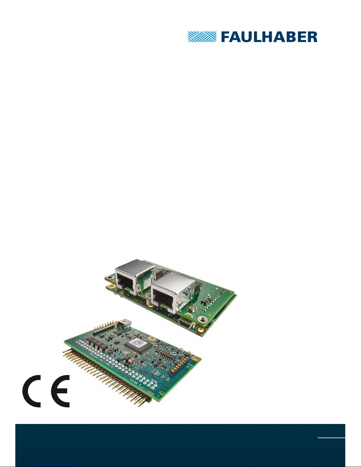
MC 5004 P STO
Original Instructions
EN

Imprint
2
Version:
1st edition, 03-05-2018
Copyright
by Dr. Fritz Faulhaber GmbH & Co. KG
Daimlerstr. 23 / 25 · 71101 Schönaich
All rights reserved, including those to the translation.
No part of this description may be duplicated, reproduced,
stored in an information system or processed or
transferred in any other form without prior express written
permission of Dr. Fritz Faulhaber GmbH & Co. KG.
This document has been prepared with care.
Dr. Fritz Faulhaber GmbH & Co. KG cannot accept any
liability for any errors in this document or for the
consequences of such errors. Equally, no liability can be
accepted for direct or consequential damages resulting
from improper use of the equipment.
The relevant regulations regarding safety engineering
and interference suppression as well as the requirements
specified in this document are to be noted and followed
when using the software.
Subject to change without notice.
The respective current version of this technical manual is
available on FAULHABER's internet site:
www.faulhaber.com
1st edition, 03-05-2018 7000.05063, 1st edition, 03-05-20187000.05063

1st edition, 03-05-2018 7000.05063, 1st edition, 03-05-20187000.05063
Content
3
1 About this document ....................................................................................................... 5
1.1 Validity of this document ...................................................................................... 5
1.2 Associated documents ............................................................................................ 5
1.3 Using this document .............................................................................................. 5
1.4 List of abbreviations ............................................................................................... 6
1.5 Symbols and designations ...................................................................................... 7
2 Safety ................................................................................................................................ 8
2.1 Intended use ........................................................................................................... 8
2.2 Safety instructions .................................................................................................. 9
2.2.1 Dangers in the event of damages and changes.................................... 9
2.2.2 Correct installation and commissioning .............................................. 10
2.2.3 Heat development ................................................................................ 10
2.3 Environmental conditions .................................................................................... 10
2.4 Requirements on the higher-level control .......................................................... 11
2.5 EC directives on product safety ........................................................................... 12
3 Product description ........................................................................................................ 13
3.1 General product description ................................................................................ 13
3.2 Product information ............................................................................................. 15
3.3 Technical data ....................................................................................................... 16
3.4 Product variants .................................................................................................... 17
3.4.1 Controller PCBs...................................................................................... 17
3.4.1.1 Standard PCB.......................................................................... 17
3.4.1.2 EtherCAT PCB ......................................................................... 18
3.4.1.3 State machine and start routine ........................................... 20
3.4.2 Motherboard......................................................................................... 23
4 Installation ...................................................................................................................... 25
4.1 Mounting .............................................................................................................. 25
4.1.1 Mounting instructions .......................................................................... 25
4.1.2 Installing the Motion Controller PCB on the motherboard ............... 26
4.1.3 Installing the Motion Controller PCB in the top-hat-rail housing ..... 27
4.2 Electrical connection ............................................................................................ 28
4.2.1 Notes on the electrical connection ...................................................... 28
4.2.2 Drive connections.................................................................................. 29
4.2.3 Screening ............................................................................................... 30
4.2.4 Connection of the power supply ......................................................... 31
4.2.4.1 Power supply.......................................................................... 31
4.2.5 Connector pin assignment.................................................................... 32
4.2.5.1 Pin assignment of the X100 connector strip of the
Motion Controller.................................................................. 32
4.2.5.2 Pin assignment of the motherboard (motor side) ............... 34
4.2.5.3 Pin assignment of the motherboard (supply side)............... 39
4.2.6 Motherboard: connection at the motor side ...................................... 41
4.2.7 I/O circuit diagrams ............................................................................... 44
4.2.7.1 Inputs...................................................................................... 44
4.2.7.2 Outputs................................................................................... 47
4.2.8 External circuit diagrams ...................................................................... 50

1st edition, 03-05-2018 7000.05063, 1st edition, 03-05-20187000.05063
Content
4
4.3 Information on initial commissioning ................................................................. 54
5 Maintenance and diagnostics ........................................................................................ 55
5.1 Maintenance tasks ................................................................................................ 55
5.2 Diagnostics ............................................................................................................ 55
5.2.1 Standard PCB ......................................................................................... 55
5.2.2 EtherCAT PCB ........................................................................................ 56
5.2.3 Self-test .................................................................................................. 57
5.3 Troubleshooting ................................................................................................... 57
6 Accessories ...................................................................................................................... 58
7 Warranty ......................................................................................................................... 59
8 Additional documents .................................................................................................... 60
8.1 Data sheet ............................................................................................................. 60
8.2 Declaration of Incorporation ............................................................................... 62
8.3 Declaration of Conformity ................................................................................... 63
8.4 EC type-examination certificate .......................................................................... 66

1st edition, 03-05-2018 7000.05063, 1st edition, 03-05-20187000.05063
About this document
5
1 About this document
1.1 Validity of this document
This document contains the information necessary for the intended use of the
MC 5004 P STO series.
This document is intended for use by trained experts authorised to perform installation and
electrical connection of the product.
All data in this document relate to the standard versions of the series listed above.
1.2 Associated documents
The following documents are part of these installation instructions. They can be down-
loaded in pdf format from the web page www.faulhaber.com/manuals.
If it is not possible to download the documents, please contact us (see reverse of this docu-
ment).
You can find the data sheet for Motion Controller series MC 5004 P STO in chap. 8.1, p. 60.
1.3 Using this document
Read the document carefully before undertaking configuration, in particular chapter
"Safety".
Retain the document throughout the entire working life of the product.
Keep the document accessible to the operating and, if necessary, maintenance person-
nel at all times.
Pass the document on to any subsequent owner or user of the product.
Document Description
Motion Manager 6 Operating instructions for FAULHABER Motion Manager PC software
Quick start guide Description of the first steps for commissioning and operation of FAULHABER
Motion Controllers
Drive functions Description of the operating modes and functions of the drive
Accessories manual Description of the accessories
Table of contents
Other Faulhaber Motherboard manuals


