Favero 265-10 Manual

ENGLISH
Art.265-10: Radio Receiver
for FS Scoreboards Installation and service manual
General index
1. INTRODUCTION...........................................................1
2. ELECTRICAL POWER SUPPLY SYSTEM.............................1
3. SERIAL DATA CA LE SYSTEM.......................................1
4. INSTALLING THE RECEIVER...........................................2
4.1 Selecting the correct position.......................................2
4.2 Installing on wall..........................................................2
4.3 Installing on the 24 seconds shot clock scoreboard....2
5. CONNECTING AND TESTING THE SCORE OARD.................3
5.1 Connecting the Radio Receiver...................................3
5.2 Procedure o Associating the Radio Receivers...........3
5.3 Testing the Radio Receiver........................................3
6. MAINTENANCE...........................................................3
6.1 Mal unctions................................................................4
6.2 Replacing the control board........................................4
6.3 Replacing the micro controller.....................................5
6.4 Replacing the power supply........................................5
1. INTRODUCTION
This manual covers all aspects o installation and maintenance o the Radio Receiver or electronic FS series scoreboards; or
the Radio Receiver to unction properly, it is important that it is installed correctly: please read the manual care ully be ore
attempting to install the Radio Receiver. The Command Console o the scoreboards must be equipped with a Radio
Transmitter.
2. ELECTRICAL POWER SUPPLY SYSTEM
Since every Radio Receiver is provided with a power supply cable and plug, we suggest that a power cord socket controlled
by an easily accessible switch be placed nearby. It is convenient to use the one provided with the various scoreboards.
3. SERIAL DATA CA LE SYSTEM
The Radio Receiver has three identical serial data output ports (Fig. 8) to which the various electronic scoreboards can be
connected; to install the cables ollow the directions below:
•do not pass the cable through the same ducts used or the electrical cables; this is to ensure sa ety, as well as to prevent
receiving electrical inter erence rom motors, air-conditioners, uninterruptible power supplies, etc.;
•avoid placing the cable where it may be exposed to high temperatures, mechanical damage, or vandalism.
Seeing there is only one Radio Receiver, it is best to place it close to the cables connecting the various boards; examples o
con igurations are shown in Fig. 1 and Fig. 2 below.
265-I01E Rx Radio FS Installation Page 1 / 5 FAVERO ELECTRONIC DESIGN
Art.265-10 - Radio Receiver or FS scoreboards

ENGLISH
Seeing that there are more than one Radio Receivers, the best position or each Receiver is that which allows the least
amount o cable to be used (see Fig. 3 and Fig. 4).
4. INSTALLING THE RECEIVER
Be ore installing the Radio Receiver on the wall, we suggest irst running a preliminary test by temporarily connecting
the Receiver to the scoreboards and to the mains power supply (see chapter 5.1).
4.1 SELECTING THE CORRECT POSITION
Even though the type o radio transmission used is very reliable, since the
radio channel is selected automatically in order to avoid inter erence rom
other transmitters, and the communication distance outdoors is 500m, it is
advised that or indoor environments, and in the presence o metal
structures, the receiver is installed in a position that meets the ollowing
requirements:
•there are no visible obstacles between the Radio Receiver and the
Command Console (Fig. 5);
•there are not a lot o metal walls nearby;
•the Radio Receiver is easily accessible.
4.2 INSTALLING ON WALL
1. Make two holes with a diameter o 6mm each in the wall (Fig. 6).
2. A ter inserting the dowels, align the Receiver and attach it to the wall
by inserting and tightening the screws. Note that the protection tube o
the antenna must be in a vertical position.
4.3 INSTALLING ON THE 24 SECONDS SHOT CLOCK SCORE OARD
The various FS-24s scoreboard models displaying 24 second shot clocks require that the Radio Receiver be installed directly
on the scoreboard’s rear panel (Fig. 7) by using the screws provided.
FAVERO ELECTRONIC DESIGN Page 2 / 5 265-I01E Rx Radio FS Installation
Fig. 3: Connecting more than one Radio Receiver: example 3 Fig. 4: Connecting more than one Radio Receiver: example 4
Fig. 1: Conncecting the Radio Receiver: example 1 Fig. 2: Connecting the Radio Receiver: example 2
Fig. 5: Position o the Radio Receiver

ENGLISH
5. CONNECTING AND TESTING THE SCORE OARD
Once the Radio Receiver has beem installed, you can
proceed with connecting the electrical power supply and the
serial data cables.
5.1 CONNECTING THE RADIO RECEIVER
1. Make sure you have disconnected the power supply by
turning o the power switch.
2. Insert the power cord plug (Fig. 8) into the wall socket
(chapter 2).
3. Connect the electronic scoreboards to the Radio Receiver
via the serial data cables.
5.2 PROCEDURE OF ASSOCIATING THE RADIO RECEIVERS
At this point the Radio Receiver should be associated with
the designated Command Console, so that it only receives
data rom this console and no other.
4. Switch on the Command Console and only
the Radio
Receiver(s) which are associated with it, making sure that
no other Consoles are switched on.
5. I there are other Radio Receivers in the same location or
vicinity associated with other Consoles, it is advised to
check that they are switched o , in order or them to not
be involved in the associating procedure.
6. From the Command Console press the buttons ; select “Yes” rom the parameter “Connect new
scoreboards” and wait circa 1 minute until the value “No” returns automatically.
The Radio Receiver should now be associated with the Command Console and will begin sending data to the various
connected scoreboards; a ter this initial set up, you do not have to repeat the procedure when switching on the Console again;
connection to the Console will occur automatically: the procedure will need to be repeated only i you wish to connect the
Receiver to another Command Console.
Note that all Radio Receivers which are switched on and unctioning will be permanently associated with the
Console, provided that they are not already in communication with other Consoles.
5.3 TESTING THE RADIO RECEIVER
Once the Radio Receiver has been installed and associated with the Command Console:
1. Through the proper hole, make sure that the red LED inside the Receiver is illuminated and lashing (Fig. 8); i it is not
illuminated, substitute the power supply (chapter 6.4). I it is illuminated but not lashing, check the radio connection
(chapter 6.1.3).
2. Make sure that the scoreboards display all the in ormation present on the Console’s screen; otherwise, see chapters 6.1.1,
6.1.2, 6.1.3.
6. MAINTENANCE
This chapter contains in ormation on how to quickly resolve the main problems that may occur with the Radio Receiver over
time. For problems with scoreboards, consult the relative installation manuals. I you have urther problems that cannot be
solved herein, please contact us.
265-I01E Rx Radio FS Installation Page 3/ 5 FAVERO ELECTRONIC DESIGN
Fig. 8: Connecting the scoreboards
Fig. 6: Detail o installation on wall Fig. 7: Installation on FS-24s scoreboard

ENGLISH
For all mal unctions, the ollowing is a list o operations, ranked according to priority
, that should be carried out to re-establish
the Radio Receiver’s proper unctioning.
6.1 MALFUNCTIONS
6.1.1 The Radio Receiver - controlled scoreboard lights up for 1 second but then switches off completely.
1. Repeat the procedure o associating the Receiver to the Console (chapter 5.2, points 4-6).
2. I you have another radio Console, try using it (e ectuating the associating procedure).
3. Check that there is power supply at the socket or the Radio Receiver.
4. By looking through the proper hole (Fig. 8), check the red LED o the Radio Receiver:
a)
When the red LED is turned o
, measure the electrical voltage coming out o the internal power supply (chapter
6.4); i it measures +12Vdc, then change the control board (chapter 6.2), otherwise substitute the power supply
unti (chapter 6.4).
b)
When the red LED is illuminated but not lashing
there is power voltage but the data is not being received rom
the Console; increase the quality o radio communication by bringing the Console and the Radio Receiver nearer
together, and by eliminating any obstacles between the two. I no improvement occurs, substitute the control
board (chapter 6.2).
c)
When the red
LED is lashing
the Radio Receiver is correctly receiving data rom the Console, but the data is not
being sent to the Scoreboard.
5. Try using another serial data output port o the Radio Receiver (Fig. 8).
6. Check that the serial data cable is properly connected to the scoreboard and to the Radio Receiver and that there are
no signs o abrasions, cuts or damage.
7. Temporarily disconnect the serial data cable rom the Radio Receiver and connect it directly to one o the “DATA
SERIAL OUTPUTS” ports o the Console; i the scoreboard unctions properly then substitute the control board o the
Radio Receiver (chapter 6.2), otherwise substitute the serial data cable.
6.1.2 The scoreboard displays data that does not correspond to the data of the Console.
When the scoreboard displays data which is not congruent with the data sent rom the Command Console, it means that
the Radio Receiver has been connected to another Console by mistake; this happens when the Receiver is le t on during
a phase o association made by the Console.
1. Repeat the procedure o associating the Receiver to the Command Console (chapter 5.2, points 4-6).
6.1.3 While operating, the scoreboard does not update data or it switches on and off.
I the scoreboard does not immediately update the data rom the Console, or i it switches on or o irregularly, it means
that there has been a deterioration in the radio connection between the Console and the Receiver.
1. Make sure that the Console’s antenna is in a vertical position.
2. Eliminate any obstacles that may be present (metal structures, people, equipment, etc.) between the Console and
the Receiver (Fig. 5).
3. Disconnect the power supply rom both the Command Console and the Radio Receiver or a ew seconds, so that
when turned on again, they automatically reconnect through a new radio channel with less inter erence.
4. Try placing the Command Console closer to the Radio Receiver.
6.2 REPLACING THE CONTROL OARD
1. Disconnect the power supply cord and the serial data cables o the Radio Receiver (Fig. 8).
2. Detach the Radio Receiver rom the wall (Fig. 6) and then unscrew the 4 ront screws (Fig. 9) in order to remove the top casing.
3. On the radio module, extract the thin antenna cable rom the connector; then with a screwdriver remove the power supply
FAVERO ELECTRONIC DESIGN Page 4 / 5 265-I01E Rx Radio FS Installation
Fig. 9: Lock nuts on the control board Fig. 10: Opening the top casing

ENGLISH
wires rom the terminals (Fig. 11).
4. Remove the lock nuts rom the back o the device (Fig. 10) and remove the control board rom its casing (Fig. 11).
5. Position and asten the new board; then reconnect the power supply wires into the terminals and reconnect the thin
antenna cable.
6. Replace the top casing on the Receiver and install on the wall. Then connect the cables.
6.3 REPLACING THE MICRO CONTROLLER
1. Open the top casing o the Receiver as indicated in points
1-2 o chapter 6.2.
2. Find the micro controller (Fig. 11) and extract it rom its
base by alternately prying each o the shortest edges with
a small screwdriver (Fig. 12).
3. Insert the new micro controller making sure it aces the
correct direction; then close the Receiver with the top
casing and install on the wall. Connect the cables.
6.4 REPLACING THE POWER SUPPLY
1. Open the top casing o the Receiver as indicated in point
1-2 o chapter 6.2.
2. Disconnect the power supply wires rom the terminals o
the control board (Fig. 11).
3. With a 7 mm wrench, unscrew the nuts in order to
remove the metal lock plate o the power supply (Fig.
13).
4. Insert and asten the new power supply unit, then
connect the power supply wires to the control board. Close the Receiver by replacing the top casing. Install on the wall
and connect the cables.
265-I01E Rx Radio FS Installation Page 5/ 5 FAVERO ELECTRONIC DESIGN
Fig. 11: Control board Fig. 12: Replacing the micro controller
Fig. 13: Replacing the power supply unit
Table of contents
Popular Receiver manuals by other brands

Furuno
Furuno RV-107 Operator's manual
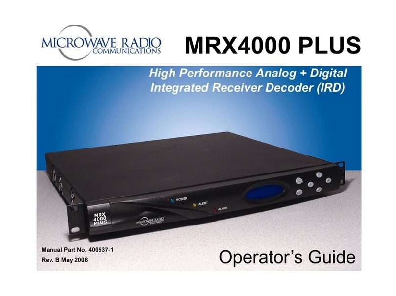
Microwave Radio Communications
Microwave Radio Communications MRX4000 PLUS Operator's manual
Onkyo
Onkyo HT-RC660(B) Service manual
JVC
JVC CD Receiver KW-XG701 installation manual
Integra
Integra MAYFIELD Swivel Adaptor instruction manual
GeoMax
GeoMax Zenith15 quick guide
