Favor.it RS10 Manual

RS10/18/22 Favor.it
INSTALLATION AND MAINTENANCE MANUAL INDUSTRIAL WASHER-
PUBLICATION DATE: 2 Oct 2006 EXTRACTORS
523323

523323 PUBLICATION DATE 2 OCT 2006.DOC INSTALLATION AND MAINTENANCE MANUAL 1
1. CONTENTS
Publication date 2 Oct 2006 Page:
1. CONTENTS.....................................................................................................................1
2. WARNINGS AND SYMBOLS .........................................................................................2
2.1. PERSONAL SAFETY RULES.............................................................................................................2
2.2. SYMBOLS ON THE MACHINE...........................................................................................................2
2.3. IMPORTANT INFORMATION BEFORE INSTALLATION....................................................................3
3. TECHNICAL INFORMATION..........................................................................................4
3.1. TECHNICAL SPECIFICATIONS 10/18/22 kg - 25/40/50 lbs CAPACITY..............................................4
3.2. DIMENSIONS AND COMPONETS OF THE MACHINE ......................................................................6
4. INSTALLATION OF THE MACHINE...............................................................................8
4.1. HANDLING, TRANSPORT, STORAGE AND UNPACKING.................................................................8
4.2. SPACE REQUIREMENTS..................................................................................................................8
4.3. MACHINE'S POSITIONING................................................................................................................8
4.4. CONNECTIONS...............................................................................................................................11
4.5. PUTTING INTO SERVICE................................................................................................................14
5. MAINTENANCE............................................................................................................15
5.1. INTRODUCTION..............................................................................................................................15
5.2. DAILY...............................................................................................................................................15
5.3. EVERY THREE MONTHS................................................................................................................15
5.4. EVERY SIX MONTHS ......................................................................................................................15
5.5. WATER FILTER...............................................................................................................................16
5.6. TIGHTENING OF BOLTS.................................................................................................................16
5.7. DOOR SEAL ....................................................................................................................................16
5.8. BELTS OF DRIVE ............................................................................................................................16
1.9. FUSES.............................................................................................................................................18
6. TROUBLE SHOOTING AIDS........................................................................................19
6.1. EMERGENCY DOOR OPENING......................................................................................................19
6.2. FILLING TIME TOO LONG...............................................................................................................19
6.3. HEATING TIME TOO LONG.............................................................................................................19
6.4. DRAIN TIME TOO LONG .................................................................................................................19
6.5. PROGRAMMER PROBLEMS...........................................................................................................19
7. LIST OF RECOMMENDED SPARE PARTS.................................................................20
8. PUTTING THE MACHINE OUT OF SERVICE..............................................................21
8.1. DISCONNECTING THE MACHINE...................................................................................................21
8.2. MACHINE LIQUIDATION..................................................................................................................21
2 INSTALLATION AND MAINTENANCE MANUAL 523323 PUBLICATION DATE 2 OCT 2006.DOC
2. WARNINGS AND SYMBOLS
TO MINIMIZE THE RISK OF FIRE, INJURY BY ELECTRIC SHOCK OR SERIOUS INJURIES
OF PERSONS OR PROPERTY DAMAGE, PLEASE READ AND FOLLOW THE FOLLOWING
INSTRUCTIONS:
2.1. PERSONAL SAFETY RULES
GENERALLY
•This English version isthe original version.
•This instruction is not complete without „User’s“, „Programming“, and „Spare parts manual”.
•Before installation, operation and maintenance of the machine read carefully the complete instructions supplied
with the machine, i.e. this „Installation and maintenance manual“, „User’s manual“, „Programming manual“ and
„Instruction manual for frequency inverter“. Keep the manuals in a handy place.
•Do not bypass the safety instructions stated in manuals and warnings on the labels. Basic safety instructions
stated in chapters „2. Warnings and symbols“ of the supplied manuals should be printed and located near
the machine for the operator's use. The labels must be readable and permanently located on the machine!
•Follow all valid local safety instructions and laws !
•Do not use the machine with its parts damaged, missing parts or opened covers!
•Do not store any flammable materials near the machine. Storing of chemicals near the machine or operating
dry cleaning machines in bad technical conditions can cause a health damage or the machine parts corrosion.
•Do not tamper with themachine controls.
•The washer extractor isintended to be permanently connected to fixed wiring.
•The machine must be connected to the power, ground, water and ventilation according to the installation manual,
in compliance with the local standards done by qualified technicians with proper authorization. The valid
standards for connecting to the local power network (TT / TN / IT, ...)must be followed. In the standard
execution, the washer may not be suitable for connecting to an IT supply system.
•If you have a machine with frequencyinverter do not change the parameters of the inverter. Doing so can cause
serious injury, fire, machine damage, etc.
•Instructions and warnings included in this manual do not cover all possible conditions and situations that can
occur at installation, maintenance or operations of the machine. They must be understand in common sense.
Caution and carefulness are factors that can not be achieved by the design of machine. These factors are
conditioned by qualification and competence of personnel who install, operate and maintain the machine.
•In case of a problem or situationsthat you can not solve by yourselves, contact your qualified serviceman,
manufacturer or the dealer. Always state the model and serial number of your machine from the completed
last page of themanual.
•The emergency stop deviceis omitted on machines design for coin, token, external payment system or similar
operation for use in self-service situation. The owner-installer-user must provide a remote-located emergency
stop device that is connected to each machine.
FOR MAINTENANCE
•When the main switch is off, the inlet terminals of the switch are still under current!
•Do not bypass any safety devices or their parts. Anyinterference to the machine function and design are
prohibited and the manufacturer does not bear any responsibilities in such cases!
•Before maintenance activities always disconnect the machine power supply!
•Do not repair or replace any machine parts and do not perform machine service work if it is not recommended
in the maintenance instructions. All other service activities should be provided by qualified service workers.
•Do not repair or adjust themachine belt drives while in operation. Turn off the main switch!
•Original or identical parts must be used for replacement inthis machine. After servicing replace and secure all
panels in the original way. Takethese measures for continued protection against electrical shock, injury, fire
and/or property damage.
•Once in 3 months, check the earthing and the emergency function.
•Keep the machine top clean and free of flammable materials. Do not wash or spray the machine by water.
INSTALLATION AND SERVICE CAN BE DONE BY A SERVICE ORGANIZATION WITH PROPER
AUTHORIZATION FROM THE MANUFACTURER.
The machine warranty can be cancelled if the instructions of this manual are not followed.
2.2. SYMBOLS ON THE MACHINE
Danger, read and follow written instructions
Caution, high power voltage, electrical devices
Press push button in case of emergency

523323 PUBLICATION DATE 2 OCT 2006.DOC INSTALLATION AND MAINTENANCE MANUAL 3
2.3. IMPORTANT INFORMATION BEFORE INSTALLATION
FOR TRANSPORTATION AND STORAGE
IN CASE OF TRANSPORTATION AND STORAGE, WATCH COMPONENTS PROTRUDING FROM THE
CONTOUR LINE OF MACHINE (DOOR LOCKS ETC.), TO AVOID INJURIES.
•Never push, pull or exert pressure on components protruding from the machine contour line (controls, door locks
etc.).
•Make sure that these components are secured so as to avoid damages during machine manipulation and
installation.
•In case of the machine transportation by the customer, follow the manufacturer's instructions for transportation,
handling and storage of the product. In case of transportation of machine bythe customer the manufacturer is
not responsible for possible damage of machine in the course of transportation.
•The ambient temperature of transportation and storage must be between -25°C - +55°C. Relative humidity must
be between 30% - 90% without condensation. In case of storagethe machine in a free areait must be protected
against mechanical damage and weather condition factors.
FOR INSTALLATION
ELECTRICAL CONNECTION, EARTHING AND VENTING OF THE MACHINE, WATER INLETS AND
DRAINAGE MUST BE PERFORMED BY QUALIFIED PERSONNEL WITH A PROPER AUTHORIZATION
ACCORDING THE INSTALLATION MANUAL IN COMPLIANCE WITH LOCAL STANDARDS
(APPLICABLE ALSO FOR STEAM CONNECTION ON STEAM HEATED MACHINES).
•Do not install the machine at places exposed to climatic effects or excessive humidity. The machine is not
designed to accept environment with sprayed water.
•Any changes in the machine installations must be approved by dealer or manufacturer. Otherwise the
dealer/manufacturer is not responsible for possible injuries or damages. Interference and changesin the
machine construction are not allowed and the manufacturer refuses any responsibilities in such cases.
•Define dangerous areas in the laundry room and do not allow people to enter if themachine is in operation.
MACHINE VERSION
•This manual contain information for the whole series of rigid mounted machine types with filling of dry linen 10,
18 and 22 kg (25, 40 and 50 lb). Check, please, the type of your machine on the production label (located on
back of machine) and look for right information in the manual.
•Machines are equipped with an electronic programmer MCB EC. The „OPL“ is a version with a programmer
controlled only by push-buttons.
•The version with an electronic programmer is : 1 motor controlled by frequency inverter.
•Starting of the machine comes by a start push-button.
•Heating is provided by electrical heating elements.
•Water valves are used for cold hard, cold soft and if necessary warm water.
•The machine electrical connection is three-phases 3AC/380-415V+N. Machines in accordance to CE directives
are „CE“ marked on themachine name plate.
•The machine design which fulfilsThe European Agreement requirements is stated in the name plate by the
symbol „CE“.
•All machines types are produced according the EMC-directive (Electro-Magnetic-Compatibility). They can be
used in restricted surroundings only (comply minimally with class A requirements). For safety reasons there must
be kept the necessary precaution distances with sensitive electrical or electronic device(s).
•The product fulfils the technical requirements for a product determined by the law no. 22 / 1997 of Digest of
Czech Republic.
•The used electrical standard for concerned machines covered by this manual depends on the scope
of the considered standards in which the machine best fits. The chosen electrical standard ismentioned in the
declaration of conformity that is delivered by each machine.
4 INSTALLATION AND MAINTENANCE MANUAL 523323 PUBLICATION DATE 2 OCT 2006.DOC
3. TECHNICAL INFORMATION
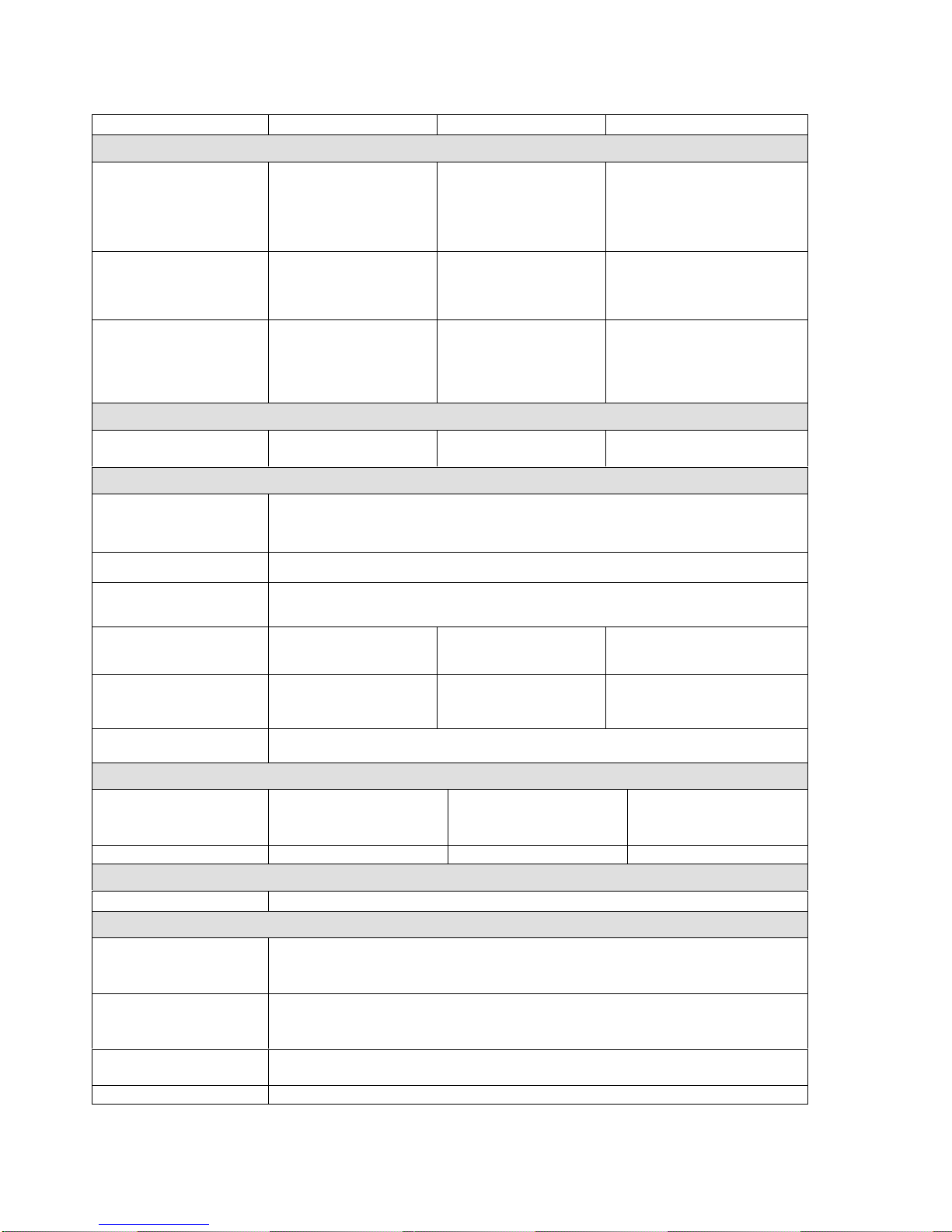
3.1. TECHNICAL SPECIFICATIONS 10/18/22 kg - 25/40/50 lbs CAPACITY
CAPACITY: 10 kg / 25 lb 18 kg / 40 lb 22 kg / 50 lb
DIMENSIONS
PACKING:
width
depth
height
transportation capacity
carton box
700 mm / 27.6"
880 mm / 34.64"
1280 mm / 50.39"
0.8 m3/ 28.25 ft3
carton box
935 mm / 36.8"
955 mm / 37.6"
1530 mm / 60.2"
1.37 m3/ 48.4 ft3
carton box
935 mm / 36.8"
1050 mm / 41.3"
1530 mm / 60.2"
1.5 m3/ 52.9 ft3
MACHINE:
width
depth
height
660 mm / 26"
865 mm / 34"
1140 mm / 44.9""
855 mm / 33.7"
895 mm / 35.2"
1315 mm / 51.8"
855 mm / 33.7"
990 mm / 39"
1315 mm / 51.8"
INNER DRUM:
diameter
depth
drum capacity
door opening
530 mm / 21"
420 mm / 16.5"
95 dm3/ 25 gal
290 mm / 11.4"
700 mm / 27.6"
470 mm / 18.5"
181 dm3/ 47.8 gal
410 mm / 16.1"
700 mm / 27.55"
565 mm / 22.4"
217 dm3/ 57.3 gal
410 mm / 16.1"
WEIGHT
netto
brutto 185 kg / 408 lb
210 kg / 463 lb 300 kg / 662 lb
335 kg / 739 lb 305 kg / 673 lb
350 kg / 772 lb
ELETRICAL DATA
Permitted deviations
of feeding voltage for
machines (with load
and without load): ±10%, with a maximal standard deviation of the frequency 1%
Electrical system of
the machine: 3x380-415V+N 50/60Hz
Minimal power supply
voltage
(validforfrequencycontroll) 350V
NOMINAL MOTOR
OUTPUT 600 W 1,5 kW 1,5 kW
INPUT PROTECTION
FOR ONE MACHINE:
Heating power / fuse 9kW / 20A 12kW / 25A 18kW / 32A
Overload protection
of the motor: external thermal motor protection or electronic protection by the frequency inverter
WASHING FUNCTION
RPM OF THE DRUM:
washing
extracting 45 rpm
525 rpm 44 rpm
505 rpm 44 rpm
480 rpm
G - factor of spinning 100 100 90
HEATING
TYPE OF HEATING: 100% electric
CONNECTIONS
WATER INLETS:
water pressure
water inlet 0.4 - 1.0 MPa / 60-145 PSI
3/4"
WATER DRAINAGE:
dimension
capacity 76 mm / 3“
Connections to external
liquid soap supply: standard 5 or 8 pcs,
(see electrical scheme)
Soap hoppers: 3
Tab. 3.1
*

523323 PUBLICATION DATE 2 OCT 2006.DOC INSTALLATION AND MAINTENANCE MANUAL 5
CAPACITY: 10 kg / 25 lb 18 kg / 40 lb 22 kg / 50 lb
CONSUMPTION
Average water
constumption: 90 dm3/ 24 gal 160 dm3/ 43 gal 191 dm3/ 50,5 gal
WORKING CONDITIONS
ambient temperature:
average ambient
temperature in 24 hrs:
relative humidity:
height above sea level:
from +5°C to +40°C
to +35°C
30% ÷95% without condensation
to 1000 m
ANCHORING
Bolt: 6 pcs M16 x 160
max.static loading of floor:
(with linen and water)
max.dynamic loading:
(alternative stress when
extracting)
frequency of dynamic
loading:
216 kg / 474 lb
450 kg/m2
8,42 Hz
310 kg / 682 lb
890 kg/m2
8,42 Hz
320 kg / 704 lb
960 kg/m2
8 Hz
NOISE
Average noise level at
max. loading: 66.6 dB (A)
Tab. 3.1. continuation
maximum dimensions including protruding parts
*
6 INSTALLATION AND MAINTENANCE MANUAL 523323 PUBLICATION DATE 2 OCT 2006.DOC
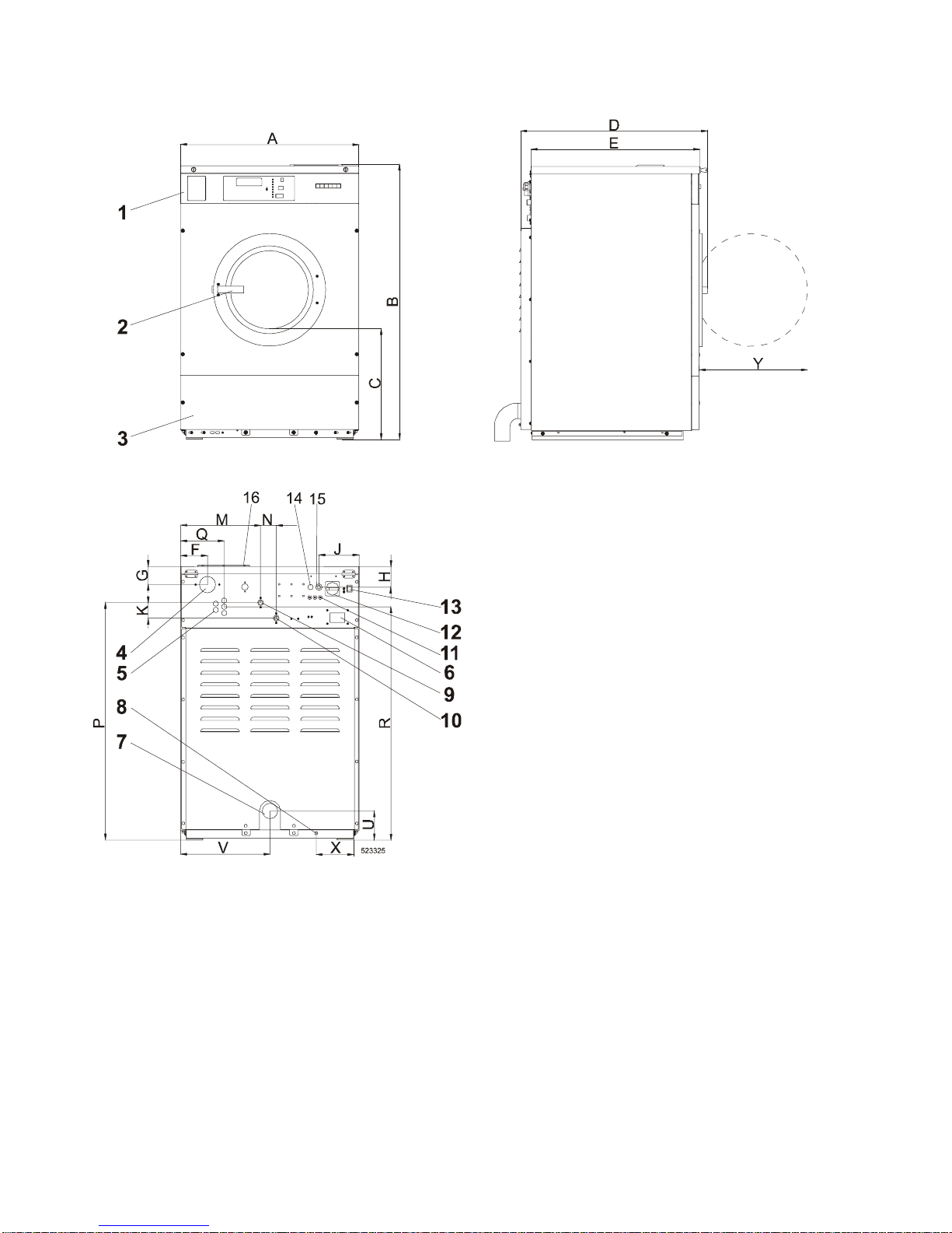
3.2. DIMENSIONS AND COMPONETS OF THE MACHINE
Fig. 3.2
1. Control panel
2. Door handle
3. Service panel
4. Air vent
5. Liquid soap hose connections
6. Name plate
7. Drain connection
8. Earthing connection
9. Hot water connection
10. Cold soft water connection
11. Fuses
12. Main switch
13. Program accelerator button
14. Electrical connection to liquid soap
pumps
15. Electrical connection of machine
16. Soap hoppers

523323 PUBLICATION DATE 2 OCT 2006.DOC INSTALLATION AND MAINTENANCE MANUAL 7
Machine capacity: 10 kg
25 lbs 18 kg
40 lbs 22 kg
50 lbs
A660 mm
26" 855 mm
33.7 " 855 mm
33.7 "
B1140 mm
44.9 " 1315 mm
51.8 " 1315 mm
51.8 "
C460 mm
18.1 " 528 mm
20.8 " 528 mm
20.8 "
D865 mm
34 " 895 mm
35.24 " 990 mm
38.97 "
E775 mm
30.5 " 855 mm
33.7 " 950 mm
37.4 "
F102 mm
4 " 140 mm
5.12 " 140 mm
5.12 "
G86 mm
3.4 " 94 mm
3.7" 94 mm
3.7"
H147 mm
5.8 " 157 mm
6.2 " 157 mm
6.2 "
J188 mm
7.4 " 190 mm
7.5 " 190 mm
7.5 "
K75 mm
3 " 75 mm
3 " 75 mm
3 "
M267 mm
10.5 " 382.5 mm
15.1 " 382.5 mm
15.1 "
N60 mm
2.4 " 75 mm
3 " 75 mm
3 "
P992 mm
39.1 " 1138 mm
44.8 " 1138 mm
44.8 "
Q182 mm
7.2 " 207.5 mm
8.2 " 207.5 mm
8.2 "
R949 mm
37.4 " 1117 mm
43.5 " 1117 mm
43.5 "
U92 mm
3.6 " 134 mm
5.3 " 134 mm
5.3 "
V330 mm
13 " 427,5 mm
16.8 " 427,5 mm
16.8 "
X109 mm
4.3 " 205.5 mm
8.1 " 205.5 mm
8.1 "
Y415 mm
16.3 " 521.5 mm
20.5" 521.5 mm
20.5"
Tab. 3.2

8 INSTALLATION AND MAINTENANCE MANUAL 523323 PUBLICATION DATE 2 OCT 2006.DOC
4. INSTALLATION OF THE MACHINE
4.1. HANDLING, TRANSPORT, STORAGE AND UNPACKING
Only a qualified person can handle or operate the machine.
STORAGE
The machine is delivered to the customer in a cardboard packing and the machine is additionally protected
by polyethylene foil. Do not store or install the machine where it can be exposed to environmental conditions
(rain, wind) or extreme humidity.
HANDLING DURING INSTALLATION
All activities can be done only by a worker, which knows all information about the machine. The machine is
fixed to the wooden palette by four bolts M12x60.
To remove the machine to its final location follow these precautions:
•Check all passages and spaces where the machine has to be transported through, they must have
sufficient dimensions to meet the height and width of the machine including the package.
•Never push, pull orpress the components protruding from the contour line of machine (front part, filling
door, control elements, belt cover, water inlet and outlet pipes etc.).
MAKE SURE THAT THESE COMPONENTS ARE PROTECTED, TO AVOID THEIR DAMAGE DURING
HANDLING AND INSTALLATION OF THE MACHINE.
•Make sure that the filling door are secured to avoid its opening during the handling.
•Lift the machine up bylift truck or hand-operated pallettruckusing a transport skid to which the machine has
been attached.
UNPACKING
Before you install the machine in its place, remove the package, release four bolts and lift up the machine
using the high lift truck and remove the wooden palette. It is possible to handle the machine by the fork lift
or the manual truck in such a way, so that the forks would not damage the components located in its lower
part. After unpacking, check if the machine has not been damaged and if all the accessories are included
according to your order. Verify the type of your machine by a name plate located on the machine rear and
find corresponding information in the manual. The accessories and the manual are placed inside the drum,
which can be opened according to chapter 6.1.
4.2. SPACE REQUIREMENTS
REQUIRED MACHINE WORKING CONDITIONS
See chapter „3. TECHNICAL SPECIFICATION“.
The machine may not be installed within the reach of directly spraying water. Do not install the machine
where it will be exposed to weather condition and excessive humidity. When steamed up due to temperature
changing, water must not run over the machine walls and covers, nor to cover the floor under and around it.
REQUIRED ROOM DIMENSIONS
Provided that the requirements in respect to room dimensions are not met, the maintenance of the machine
may be difficult. Leave at least a 0.6 m / 2 ft free space between the rear panel of machine and the wall.
Leave at least a 0.04m / 1.57“ free space between the side panel of machine and the wall or other machine.
Leave at least a 0.6m / 2 ft free space between the top panel of machine and the ceiling, which cannot be
dismantled (see fig. 4.3.D, dimension „J“).
4.3. MACHINE'S POSITIONING
MACHINE'S POSITIONING ON THE FLOOR
The machines must always be fixed to the floor which complies with static and dynamic machine stress.
There are two systems possible. The machine can be fixed to a concrete socle by bolts (see fig. 4.3.A, pos. 1).
It can also be bolted on a metal socle (fig. 4.3.B, pos. 9) which is fixed to the floor by bolts. The manufacturer
recommends to fix machines of the 18 kg / 40 lbs and 22 kg / 50 lbs type to the base of height 18 cm / 7“ for
easier manipulation with the linen.
For 18 kg / 40 lbs and 22 kg / 50 lbs type:
In case there are gaps between the frame of the machine and the concrete or metal socle before tightening
the bolts, use the shims delivered with the machine (see fig. 4.3.A, fig. 4.3.B, pos. 7) to fill this gaps.

523323 PUBLICATION DATE 2 OCT 2006.DOC INSTALLATION AND MAINTENANCE MANUAL 9
Fig. 4.3.A Fig. 4.3.B
Fig. 4.3.C. Position of foundation bolts for machines
6 kg / 15 lbs to 22 kg / 50 lbs
1. Foundation bolt 6. Existing floor
2. Nut
3. Machine socle 7. Shim for machine type 16 kg / 35 lbs
8. Bolt
4. Washer 9. Metal socle
5. Concrete base
Fig. 4.3.D. Base description

10 INSTALLATION AND MAINTENANCE MANUAL 523323 PUBLICATION DATE 2 OCT 2006.DOC
Kapacita
stroje 10 kg
25 lb 18 kg
40 lb 22 kg
50 lb
A530 mm
20.9 " 700 mm
27.6 " 700 mm
27.6 "
B65 mm
2.6 " 77,5 mm
3.1 " 77,5 mm
3.1 "
C100 mm
4" 100 mm
4" 100 mm
4"
D20 mm
0.79" 20 mm
0.79" 20 mm
0.79"
E48 mm
1.9 " 110 mm
4.33 " 110 mm
4.33 "
F365 mm
14.4 " 360 mm
14.17 " 500 mm
19.7 "
G295 mm
11.6 " 295 mm
11.61 " 251 mm
9.88 "
H28 mm
1.10" 39 mm
1.53 " 39 mm
1.53 "
Imin. 600 mm
27.56 " 700 mm
27.56 " 600 mm
27.56 "
J min. 600 mm
27.56 " 700 mm
27.56 " 700 mm
27.56 "
K40 mm
1.6" 40 mm
1.6" 40 mm
1.6"
L120 mm
4.7 " 120 mm
4.7 " 120 mm
4.7 "
Mmin. 300 mm
11.8 " 400 mm
15.7 " 400 mm
15.7 "
N50 mm
2" 50 mm
2" 50 mm
2"
O135 mm
5.3 " 140 mm
5.6 " 140 mm
5.6 "
PM16 x 160 M16 x 160 M16 x 160
Tab. 4.3. Dimensions of machine
523323 PUBLICATION DATE 2 OCT 2006.DOC INSTALLATION AND MAINTENANCE MANUAL 11
4.4. CONNECTIONS
ELECTRICAL CONNECTION
GENERAL
WARNING !
THE MACHINE MUST BE CONNECTED TO THE POWER, GROUND, WATER, VENTILATION AND STEAM
SUPPLY ACCORDING TO THE INSTALLATION MANUAL, IN COMPLIANCE WITH THE VALID LOCAL STANDARDS
DONE BY QUALIFIED TECHNICIANS WITH PROPER AUTHORIZATION.
THE VALID STANDARDS FOR CONNECTING TO THE LOCAL POWER NETWORK (TT / TN / IT, ...) MUST BE
FOLLOWED.INTHESTANDARD EXECUTION, THE WASHER MAY NOT BE SUITABLE FOR CONNECTING
TO AN IT SUPPLY SYSTEM.
THE WASHER EXTRACTOR IS INTENDED TO BE PERMANENTLY CONNECTED TO THE ELECTRICAL
SUPPLY.
The machines have been designed for connecting to the electrical network according to the specifications of your
order. Before connection check if the electrical values stated on the serial plate of the machine correspond
to your electrical network. If not do not connect the machine, please contact your dealer.
If the machine is not equipped with a supply disconnecting device, like a main switch then a supply disconnecting
device need to be provided in the installation for all electrical supplies connected to the machine, in accordance
with EN 60204-1 standard, point 5.3. This device shall disconnect the electrical equipment of the machine
from the supply when required e.g. maintenance.
EMERGENCY STOP DEVICE
The machines are equipped with an emergency stop device in accordance with ISO13850 - category 0 stop
function. Nevertheless, the emergency stop device is omitted on machines design for coin, token, external
payment system or similar operation for use in self-service situation. The owner-installer-user must provide
remote-located emergency stop device(s). This emergency stop device(s) needs to stop each machine
in accordance with ISO13850 - category 0. There are made provisions in the wiring harness, were immediate
removal of power to the actuators can be accomplished. See the electrical schematic of the machine for correct
connection of the device.
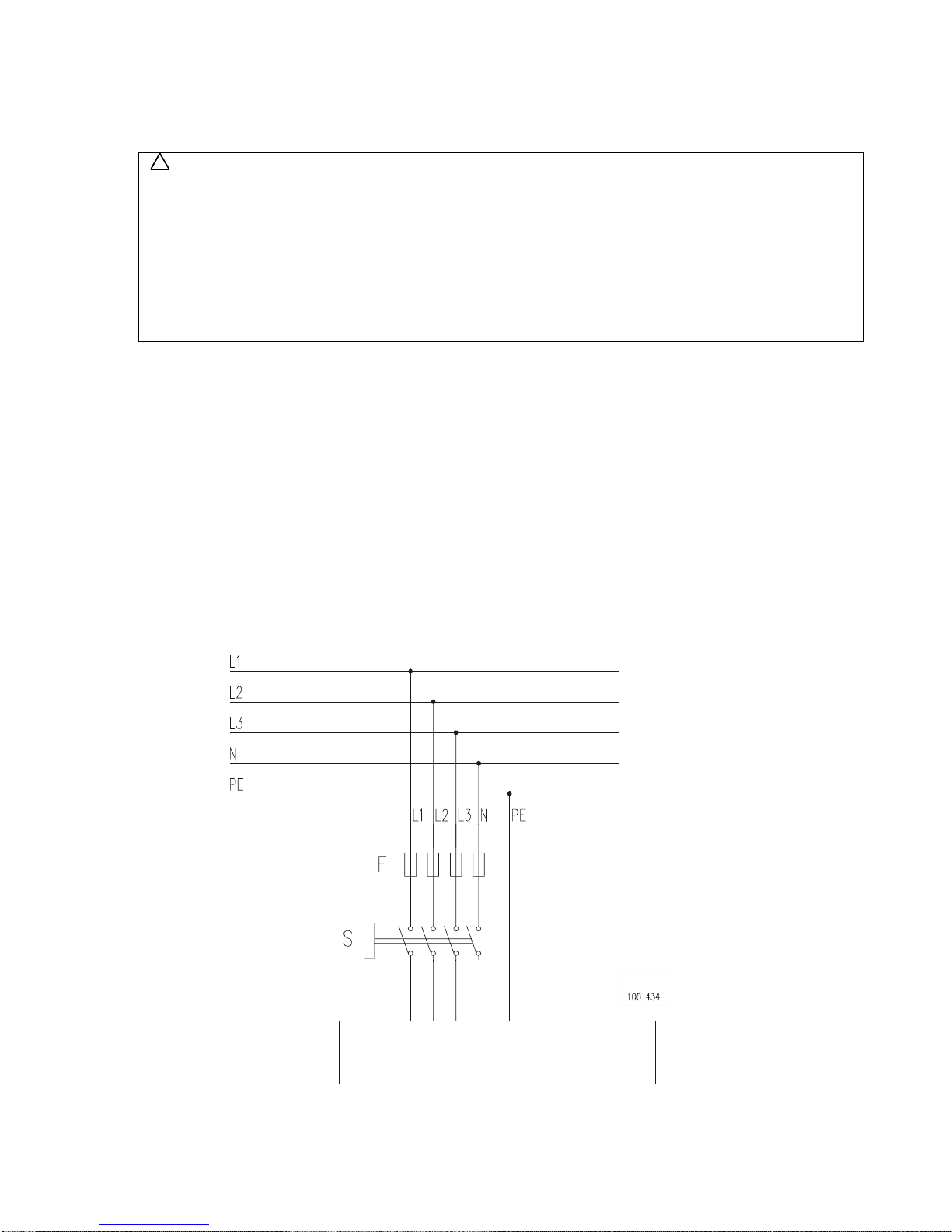
SUPPLY CABLE AND SAFETY DEVICES
Fig. 4.4.A. Example of electrical connection
!
MACHINE
12 INSTALLATION AND MAINTENANCE MANUAL 523323 PUBLICATION DATE 2 OCT 2006.DOC
Supply cable of the machine must have copper wires. The cross section of the supply wires depends
on the supply voltage and on the total electrical power input of the machine (see table 3.1). The supply cable
safety device against a short-circuit fault and overloading must be performed by automatic breakers or fuses
in the laundry switchboard. The recommended minimal cross-section of the supply wires as well as the values
of fuses (F) for the supply are stated in table 4.4.A.
In all cases were thelocal standardsrequirements are higher, these has to be followed above the recommendation
in table 4.4.A. If the local standards requireinstallation of the earth leakage trip, we suggest toinstall one of 100 mA
for the machines equipped with frequency inverter. The main contacts of the earth leakage trip must comply
with the specified power input of the machine.
POWER SUPPLY
PROTECTION (A)
MINIMAL PHASE
CONDUCTOR SECTION
(mm2)
16 2.5
25 - 32 4
40 6
50 10
60 - 80 16
Tab. 4.4.A. Minimal wire section is recommended by manufacturer.
INSTALL SUPPLY CABLE TO THE MACHINE
WARNING !
THE PROTECTIVE CONDUCTOR MUST BE LONGER SO THAT WHEN THE CABLE IS PULLED OUT
ACCIDENTALLY, THIS CONDUCTOR IS DISCONNECTED AS THE LAST ONE!
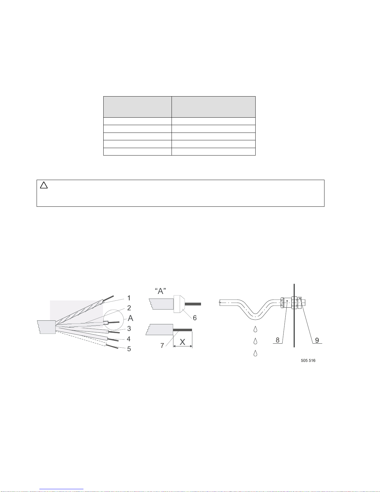
When using the cable (hard copper conductors), strip individual cores in such a way to avoid the protrusion
of a stripped part from the terminal when the conductor is connected into the device (7 - dimension X).
When using a cord (stranded copper conductors) the individual cores can be strippedin a similar way as in the case
of a cable, or use moulded tubes (6). In this case use tubes with an insulated neck to avoid a contact to a part
under tension after the conductor connection.
1. Green-yellow - protection conductor
2. Black - phase conductor
3. Brown - phase conductor
4. Black - phase conductor
5. Blue - neutral conductor
6. A neck of the moulded tube
7. The stripped length of conductors
8. Bush
9. Securing clamp
Fig. 4.4.B. Adaptation of conductor ends and supply power cable attachment
The cable can be attached to the machine in two ways. From a cable channel (from below) and from a cable
grate (from above). If the cable is attached from above, it is recommended to secure the cable against
sagging in front of the entry into the cable bush. In this way an ingress of the running condensed water into
the bush and/or machine can be avoided.
Open the top cover of the machine. When the cable is put through the bush (8), tighten the sealing bolt
of the bush. In this way the rubber ring in the bush is pressed, thus securing the cable against the water.
Provided that this mechanical securing is insufficient, use the securing clamp (9). The supply cable is connected
to the main switch of the machine (see fig. 4.4.C, pos. 1) or connection clamp (2). The phase terminals are
marked by U, V, W (L1, L2, L3). If the machine is not equipped with a main switch then supply disconnecting
devices need to be provided in the installation for all electrical supplies connected to the machine, in
accordance with EN 60204-1 standard, point 5.3. Connect the protection conductor directly to the protection
terminal located on the switchboard side. The terminal is identified by means of PE.
!

523323 PUBLICATION DATE 2 OCT 2006.DOC INSTALLATION AND MAINTENANCE MANUAL 13
1. Main switch
2. Connection clamp
3. Bush
Fig. 4.4.C. Connection of power supply cable to the machine
DURING EXTRACTION THE DRUM SHOULD ROTATE IN CLOCKWISE DIRECTION (WHEN YOU ARE
IN FRONT OF THE DOOR OF THE MACHINE). IF THIS IS NOT THE CASE THEN YOU MUST INTERCHANGE
U (L1) AND V (L2) WIRES ON SUPPLY CABLE TO MAIN SWITCH – NOT VALID FOR FREQUENCY
CONTROL.
PROTECTION
The circuit breakers and fuses are available in the laundry switchboard against the occurrence of short-circuit
or overloading. Verify, please, the number of phases and the machine voltage according to the name plate.
Look for an adequate value of the circuit breaker in technical information.
MACHINE PROTECTIVE CONNECTION
From the safety reasons it is necessary to connect the washing machine to the laundry protection system.
The external protective terminal M6 of the washing machine located on the right rear part of the washing
machine frame serves for this purpose and it identified with an earthing mark, see fig. 3.2, pos. 8.
The protection conductor enabling this connection is not part of the delivery with the washing machine.
However, for the protection purposes with the supply cable section of min. 4 mm2we recommend to select
a larger conductor section, i.e. 6 mm2.
WATER SUPPLY
The machine is equipped with 3/4“ cold (hot) water inlet valves. Use inlet pressure hoses, adapted to the
valves with seal. The best operation of the inlet valves will be obtained when the water pressure is situated
between 0.4-1 MPa / 60-145 PSI. A water pressure that is too low can unnecessary lengthen the wash cycle.
WATER HARDNESS
It is advisable to contact the water supplier for information concerning the properties of the water in your area.
Good wash results are dependent also on the water hardness. For medium to very hard water, consideration
should be made to make the water softer.
Only in some cases is the use of hard water desirable, such as adding softener in the linen.
The soap supplier can help you with making the right decisions concerning hard water, soft water, washing
programs, type of soap and other related items to have the best wash results.
Characteristics mmol / dm3dH -
Germany fH -
France England gr/gal
USA
soft 0 - 1,25 0 - 7° 0 - 12° 0 - 8,75° 0 - 3
medium 1,25 - 2,5 7 - 14° 12 - 25° 8,75 - 17,5° 3 - 7
hard 2,5 - 3,75 14 - 21° 25 - 37° 17,5 - 26,3° 7 - 15
very hard above 3,75 above 21° above 37° above 26,3° above 15
Tab. 4.4. B
WATER CONNECTION
Most machines are made with 2 or 3 water inlets. One is always marked with „soft water“. If more inlets are
present, they are marked with „Hot water“ or „Hard water“. For connection dimensions (see fig. 3.2). Always
use the flexible hose delivered with the machine, if not present, contact your dealer. In each case do not
use a fixed connection to the water supply.
For the proper function of the machine, it is necessary to keep the water pressure within the limits stated in
the technical data. It is also necessary to connect all available water inlets to a water supply. If a hard water
supply is not present, connect it with soft water. If no hot water supply is present, contact your dealer for the
proper required action.

14 INSTALLATION AND MAINTENANCE MANUAL 523323 PUBLICATION DATE 2 OCT 2006.DOC
WATER DRAIN CONNECTION
The machine is equipped with 76 mm / 3“ drain valve without pump, which should be connected to the main
drain pipe or to the gutter. The main drain pipe must have the capacity to be able to handle the total output
of all connected machines.
DRAIN
MODEL dm3gal
10 kg / 25 lbs 247 65.3
18 kg / 40 lbs 270 71.3
22 kg / 50 lbs 278 73.4
Tab. 4.4.C. The amount of drain water
AIR VENT CONNECTION
WARNING!
WATCH OUT, VAPOURS ESCAPE FROM THE MACHINE THROUGH THE AIR VENT OPENING!
DO NOT COVER OR CONNECT TO ANYTHING!
On the backside, the washers are provided with an air vent opening of O.D. 75 mm / 3".
Do not cover the washer air vent opening. It is part of the back flow prevention water system. It also takes
care that the tub can not be pressurized by water intake and vapor of the hot water, this allows for proper
measuring of the water level.
For the safety of everyone make sure that unauthorized persons cannot reach the backside of the machine.
4.5. PUTTING INTO SERVICE
1. For machine version with electronic programmer read carefully Programming manual of the programmer
delivered with your machine.
2. After machine installation initialisate the machine according instructions stated in manual.
!

523323 PUBLICATION DATE 2 OCT 2006.DOC INSTALLATION AND MAINTENANCE MANUAL 15
5. MAINTENANCE
WARNING !
ALWAYS FOLLOW SAFETY INSTRUCTIONS! DO NOT BYPASS ANY SAFETY DEVICES OR THEIR
PARTS. ANY INTERFERENCE TO THE MACHINE FUNCTIONS AND CONSTRUCTION ARE PROHIBITED!
USE THE PROPER CHEMICAL AGENTS WHICH AVOID CALCIUM SEDIMENTS ON HEATINGELEMENTS
AND OTHER MACHINE PARTS. DISCUSS THIS ISSUE WITH YOUR SUPPLIER OF WASHING PRODUCTS.
THE MANUFACTURER OF THE MACHINE IS NOT RESPONSIBLE FOR THE DAMAGE OF HEATING
ELEMENTS AND OTHER MACHINE PARTS DUE TO CALCIUM SEDIMENTS.
DO NOT OPERATE THE MACHINE WITH BROKEN / MISSING PARTS OR OPENED COVERS!
BEFORE MAINTENANCE WORK DISCONNECT THE MACHINE POWER SUPPLY!
WHEN THE MAIN SWITCH IS TURNED OFF THE INLET TERMINALS OF THE MACHINE MAIN SWITCH
ARE STILL UNDER CURRENT! THAT IS THE WAY TO AVOID INJURIES.
When replacing any parts of the machine, exchange them with original parts obtained from your dealer or ordered
through the spare parts manual!
5.1. INTRODUCTION
Preventive maintenance has been reduced to a minimum by the careful design of the machine, and the choice
of reliable components and materials.
5.2. DAILY
CHECK:
•Water (steam) inlets for leaks
•Check that the drain valve is not leaking during the washing process, and that it opens properly afterwards
(valve is open without electrical power).
•The machine should always be clean.
•Clean upper side and body regularlyin order to remove all soap traces.
•The soap hopper should be cleaned at the end of each working day. Scrap sediments whichmay have set
inside the soap hopper with a plastic spatula and flush them with warm water.
•Clean the sediments from the door seal (mainly bottom part).
•After cleaning the machine, at the end of a working day, open the door of the machine to enable airing the machine.
At the end of the day it is recommended to shut off all main water (steam) and electrical supply. However,
we don't mean the individual faucets of the machines that may not be touched once adjusted, but only
the main valves.
5.3. EVERY THREE MONTHS
•Make sure that themachine is switched off by the main switch when maintenance work is being performed and
that the other workers are informed about it.
•Dismantle the rear machine panel and check if the belt of wash motor is not damaged andif it has
the correct tension (see chapter 5.8.).
•Check visually that all tubing, piping and connections inside machine are free from leaks.
•Wipe and clean the inside of the machine, making sure that the control components are protected from moisture
and dust, during the cleaning operation.
•Put on the cover panels and turn on the power supply.
5.4. EVERY SIX MONTHS
•Regularly clean the filters of the water inlet.
•Check the tightness of the bolts according tochapter 5.6.
•For serious defects, the technical service of your dealer is always available.
BEFORE REMOVING TOP OR BACK PANEL OF THE MACHINE, SWITCH POWER OFF AND WAIT
FOR AT LEAST 10 MINUTES. BEFORE STARTING INSPECTION OF FREQUENCY INVERTER,
CHECK FOR RESIDUAL VOLTAGE ACROSS MAIN CIRCUIT TERMINALS + AND -. THIS VOLTAGE
MUST BE BELOW 30VDC BEFORE YOU CAN ACCESS THE INVERTER FOR INSPECTION.
•Clean and remove dirt and dust from:
–the cooling fin of the inverter
–the motor cooling fins
–the internal ventilator of the inverter (if present)
–the external ventilator (if present)
–the external air relieves of the machine
–check if ventilator in coolfins of inverter (if present) is functional
–check if external ventilator (if present) is functional
!
!

16 INSTALLATION AND MAINTENANCE MANUAL 523323 PUBLICATION DATE 2 OCT 2006.DOC
5.5. WATER FILTER
CLEANING OF FILTER
Close the main water supply.
IF MACHINE HOT WATER SUPPLY LINE IS TOO HOT, DO NOT CONTINUE !
DANGER OF INJURY!
If machine hot water supply line is cold and closed
you can clean the filter. Water filter is accessible after disconnecting the supply hose. Clean up the filter
and put it back.
5.6. TIGHTENING OF BOLTS
•Check protective connection of the machines and fixation by bolts in terminals.
•Disconnect the machine power supply in laundry electrical box !
Otherwise the supply terminal box of the machine is still under electricity !
If the machine isnot warm, dismantle the rear panel and tighten bolts of terminal electrical wires.
Check properly attachments of power electrical conductors in terminals (i.e.main supply terminal or switch,
contactors, motor, heating unites). After that install the panel back on themachine.
5.7. DOOR SEAL
ADJUSTMENT OF DOOR SEAL THRUST
Marking the parts during the disassembly can simplify the assembly procedure afterwards.
In order to make the maintenance and service easier, it is possible to remove separately the front panel and
service panel.
•Remove the lower service panel which is fixed by 2 bolts.
•Open the cover of the soap hopper and remove the 4 bolts whichfasten the soap hopperto the cover.
•Unlock the cover locks and remove the cover by loosening one of the hinges at the rear.
•Remove 4 bolts on the front side of thefront panel and remove the front panel. (For 18/22 kg / 40/50 Ib shift the
front panels towards each other after you unscrew 4 bolts, turn them by 90°and pull them over the open door).
•To remove the door lock, disconnect the lock electrical connection (white terminal). Loosen 2 bolts fastening
thelock to the tub.
•Loosen 6 bolts fasteningthe stainless steel foil and remove the foil from themachine,
(applicable for 10kg / 25 lbs).
•Under the door lock there are shims which can be removed to increase the pressure from the door on the tub.
•To remove the loading doorloosen the boltswhich fasten the door to the hinge.
•There are similar shims underthe hinge which can be also usedfor adjusting the door pressure.
•Assembly of thefront panel, door and door lock isdone in the reverse order of the assembly.
The door is centered towards the lock, by means of an alignment pin whichis mounted on the door.
REPLACEMENT OF DOOR RUBBER
•Open the door. Take a door glass with rubber from the stainless steel door and pull it up towards
the inside of the drum. Do it carefully not to damage the glass. Remove the rubber seal from the glass.
•Moisten the groove for door with soap water. Place a smooth cord inthe groove all around. Tighten up the
margin by cord and fit the unit tothe door opening (with the clip up). Hold one end of the cord firmly on the door.
Pull the other cord end towards the center of the glass for the rubber edge properly fit in.
5.8. BELTS OF DRIVE
REPLACEMENT OF THE FLAT BELTS FORTHE MACHINE WITH CAPACITY 10 kg / 25 lbs
•Remove the rear panel.
•Remove the belt PJ1473, see fig. 5.8.C, pos. 2 pulling it while the drum pulley (1) is rotating at same time.
•Remove the belt PJ559 (6) by pulling it off.
•Put a new belt PJ559 (6) on the tension pulley. Installation of the belt is done in reverse order compared to
its removal. Take care so that the tension springs (7) would be fasten to openingsin the pulley support and to the
frame hinge.
•The belt must be placed in the correct grooves of the motor pulley, so that it could movein the middle
of the tension pulley width.

523323 PUBLICATION DATE 2 OCT 2006.DOC INSTALLATION AND MAINTENANCE MANUAL 17
•If it is not possible to install the belt on the tension pulley, we can move themotor (16). Loosen the bolt M8 (11)
which ensures thecorrect position of the motor. Movethe motor to enable the belt installation and fasten it.
Tighten the securing bolt (11) carefully so that it would not deform the plastic washers (14,15).
•Put a newbelt PJ1473 (2) onthepulley. Installation of the belt isdone in reverse order compared to its removal.
Take care so that the tension springs (7) would be fasten to openings in the pulley support and to theframe
hinge.
•The belt must be placed in the correct grooves of the tension pulley, so that it could move in the middle of
the drum pulley width.
•Testing force of the correctly tight belt between the drum pulley and tension pulley is 100 - 110Hz, (180 - 210N),
measured by tension meter for measuring the force in the belt.
•Testing force of the correctly tight belt between the tension pulley and motor is 175 - 205Hz, (200 - 270N),
measured by tension meter for measuring the force in the belt.
•If the belt tension does not correspond to determinedvalues, we can adjust the belt tension by means of the bolt
which holds the springs or by additional moving the motor.
1. Drum pulley
2. Belt PJ1473
3. Pulley complete
4. Securing ring
5. Bolt M6x6
6. Belt PJ559
7. Spring
8. Bolt with eye M8x50
9. Nut M8
10. Pin
11. Bolt 5/16“x11/4“
12. Spring washer 8
13. Washer 8
14. Plastic washer 8,4x25x2
15. Plastic washer 8,2x12x3
16. Motor
Fig. 5.8.A. Flat belt, valid for 10 kg / 25 lbs
REPLACEMENT OF THE BELTS FOR THE MACHINE WITH CAPACITY
18 kg / 40 lbs, 22 kg / 50 lbs
1. Drum V-pulley
2. Belt PJ1956
3. Motor
4. Motor V-pulley
5. Motor board
6. Spring
Fig. 5.8.B. Flat belt, applicable for 18 kg / 40 lb,
22 kg / 50 lb

18 INSTALLATION AND MAINTENANCE MANUAL 523323 PUBLICATION DATE 2 OCT 2006.DOC
•Turning the drum pulley (1) slowly and by the belt (2) offset from its working position at the same time, you will
reach tension reduction and you can remove the pulley.
•Put the new belt of the same type on the motor pulley (4) first and then partly on the drum pulley (1), so that the
tension spring (6) is hooked. Turning the drum pulley (1) slowly put on the belt.
•The motor pulley and the drum pulley must be in one level.
•Testing force of the correctly tight belt between the drum pulley and the motor pulley measured by tension
meter formeasuring the force in the belt is 180-250N formachines 18 kg / 40 lb, 22 kg / 50 lb.
5.9. FUSES
FUSE VALUES
You can find values of fuses on electrical scheme delivered with the machine or on the machine label.
See also chapters 3.1. and 3.2.

523323 PUBLICATION DATE 2 OCT 2006.DOC INSTALLATION AND MAINTENANCE MANUAL 19
6. TROUBLE SHOOTING AIDS
6.1. EMERGENCY DOOR OPENING
Whenever the door fails to open, e.g. in case of a current failure or in emergency situation, we recommend
you to proceed as follows:
•Before the door is open, check the washing water temperature and machine parts temperature.
IF THESE PARTS ARE TOO HOT, DO NOT OPEN ! DANGER OF INJURY !
•After cooling down, remove the lower service panel by loosening the screws. Behind this service panel, at the
left side of the machine you will find a string for emergency door opening.
•While pulling this string downwards, you will unblock the door lock.
•You can open the door.
•Install the service panel.
6.2. FILLING TIME TOO LONG
LOW WATER PRESSURE:
More machines are filling up in the same time.
Filter of inlet valve is blocked (clogged):
Stop the main water supply, remove filters from inlet valves, clean up the filters and put them back.
THE HOSE IS LEAKING:
Replace the broken hose or seal on connection.
Defected inlet valve:
Replace the inlet valve.
6.3. HEATING TIME TOO LONG
SEDIMENT OR DEFECT ON THE ELECTRICAL HEATING ELEMENTS:
Replace the heating elements.
6.4. DRAIN TIME TOO LONG
DRAIN PIPE SYSTEM IS CLOGGED :
Clean it up.
NON-FUNCTIONAL DRAIN VALVE:
Clean or replace the drain valve.
6.5. PROGRAMMER PROBLEMS
See the chapter „Troubleshooting“ in the programming manual according to your machine type:
•„Programmingmanual - Electronic timer“
Other manuals for RS10
1
This manual suits for next models
2
Table of contents
Other Favor.it Washer manuals


Popular Washer manuals by other brands

Bosch
Bosch WAN280H1 Installation and operating instructions

Kenmore
Kenmore Kalypso 22082 owner's manual

Indesit
Indesit XWE 81283 Instructions for use manual

Siemens
Siemens iQ300 WM12N280HK User manual and installation instructions

LG
LG FH4G6TDG owner's manual

Hotpoint
Hotpoint WMF 740 P Instructions for use


