Faytech FAY-003 User manual

Industrial Motherboard
FAY-003

ii
E14425
First Edition
June 2018
Copyright Notice
This document is copyrighted, 2018. All rights are reserved. The original
manufacturer reserves the right to make improvements to the products described
in this manual at any time without notice.
No part of this manual may be reproduced, copied, translated, or transmitted
in any form or by any means without the prior written permission of the original
manufacturer. Information provided in this manual is intended to be accurate and
reliable. However, the original manufacturer assumes no responsibility for its use,
or for any infringements upon the rights of third parties that may result from its use.
The material in this document is for product information only and is subject to
change without notice. While reasonable efforts have been made in the preparation
of this document to assure its accuracy, the original manufacturer assumes no
liabilities resulting from errors or omissions in this document, or from the use of the
information contained herein.
The original manufacturer reserves the right to make changes in the product
design without notice to its users.
Acknowledgments
All other products’ name or trademarks are properties of their respective owners.
•AMI is a trademark of American Megatrends Inc.
•Intel®, Core™ are trademarks of Intel®Corporation.
•Microsoft Windows®is a registered trademark of Microsoft Corp.
•IBM, PC/AT, PS/2, and VGA are trademarks of International Business
Machines Corporation.
The original manufacturer reserves the right to make changes in the product
design without notice to its users.
All other product names or trademarks are properties of their respective owners.

iii
Contact Details
faytech Tech Co. Ltd.
Asian Headquarters / Production Center
Floor 5&6, Building F., Hongmen
Tech. Zone, Jihua Rd.,
Shenzhen, China 518129
+86 755 89580612
RMA-Service
faytech AG
Corporate Headquarters
Bischhäuser Aue 10
37213 Witzenhausen
Germany
+49 5542 30374 10
Support number:
Global contact number:
Support E-Mail:
Manufacturer webpage:
+49 5542 30374 30 (Germany)
+86 755 89580612 (China)
www.faytech.com
If there is a defect, you can request an RMA number (Return Merchandise
Authorization) at [email protected]. For further information please read this
instruction manual in detail.
For support outside of China, we work with local representatives / local service
partners together who may work on our behalf in our name. On request, more
information can be given by contacting the above mentioned contact details.

Contents
Chapter 1: Product overview
1.1 Package contents......................................................................... 1-1
1.2 Features ........................................................................................ 1-1
1.3 Specications............................................................................... 1-2
Chapter 2: Motherboard information
2.1 Before you proceed ..................................................................... 2-1
2.2 Motherboard layout...................................................................... 2-2
2.3 Screw size..................................................................................... 2-4
2.3.1 Component side.............................................................. 2-4
2.3.2 Solder side ...................................................................... 2-5
2.4 Central Processing Unit (CPU) ................................................... 2-6
2.5 System memory ........................................................................... 2-6
2.6 Jumpers ........................................................................................ 2-8
2.7 Connectors ................................................................................. 2-10
2.7.1 Rear panel connectors.................................................. 2-10
2.7.2 Internal connectors ....................................................... 2-11
Chapter 3: BIOS setup
3.1 BIOS setup.................................................................................... 3-1
3.2 Main menu .................................................................................... 3-2
3.2.1 System Date [Day MM/DD/YYYY] .................................. 3-2
3.2.2 System Time [HH:MM:SS] .............................................. 3-2
3.3 Advanced menu ........................................................................... 3-2
3.3.1 Trusting Computing......................................................... 3-2
3.3.2 CPUConguration .......................................................... 3-4
3.3.3 SATAConguration ........................................................ 3-4
3.3.4 USBConguration .......................................................... 3-4
3.3.5 Hardware Monitor ........................................................... 3-5
3.3.6 SIOConguration ........................................................... 3-5
3.3.7 Power Management........................................................ 3-6
3.3.8 DigitalIOPortConguration ........................................... 3-7
3.4 Chipset menu ............................................................................... 3-7
3.5 Security menu .............................................................................. 3-8
3.5.1 Administrator Password .................................................. 3-8
3.5.2 User Password................................................................ 3-8
iv

3.6 Boot menu .................................................................................... 3-9
3.6.1 BootConguration .......................................................... 3-9
3.6.2 Boot Option Priorities ...................................................... 3-9
3.7 Save & Exit menu....................................................................... 3-10
Appendix
Notices.......................................................................................................A-1
v
mSATA / MiniPCIe Rework........................................................................A-2
FAQs...........................................................................................................A-3

1-1
Chapter 1: General information
1.1 Package contents
Check your industrial motherboard package for the following items.
1 x Industrial Motherboard
If any of the above items is damaged or missing, contact your distributor or
sales representative immediately.
1.2 Features
•Intel®Atom™ processor
Apollo Lake N4200, 4C @ 2.50GHz CPU (Burst Mode), 750MHz GFX (Turbo),
~6W TDP
Apollo Lake N3350, 2C @ 2.40GHz CPU (Burst Mode), 650MHz GFX (Turbo),
~6W TDP
•1 x SO-DIMM, max. 4GB, DDR3L 1333/1600/1867 MHz
•SATA 6.0 Gb/s x 1, USB 3.0 x 4, USB 2.0 x 2
•1 x PCIe [x1] straddle type, 1 x Mini Card + mSATA (with SIM card) full/ half
size optional by BOM, 1 x M.2 E-key (22 x 30mm) for wireless devices
•HDMI, DisplayPort, LVDS, and eDP support
Chapter 1
Product overview

FAY-003
1-2
1.3 Specications
SYSTEM
CPU Intel®Atom™ processor
Apollo Lake N4200, 4C @ 2.50GHz CPU (Burst Mode), 750MHz GFX
(Turbo), ~6W TDP
Apollo Lake N3350, 2C @ 2.40GHz CPU (Burst Mode), 650MHz GFX
(Turbo), ~6W TDP
Memory
1 x SO-DIMM, max. 4GB, DDR3L 1333/1600/1867 non-ECC
Singal channel memory
Graphics Intel®HD Graphics
I/O chipset
NUVOTON NCT6116D
LAN 1 x LAN1 connector (POE LAN RJ-45 connector, POE power connect to
2x2 2.54mm pin header)
1 x LAN2 connector (Realtek PCIe Gb LAN 8111G shares ASM1182E IC
with PCIe x1)
Audio
1 x Realtek ALC3236 Audio CODEC
TPM
1 x Nuvoton NPCT652ABCYX TPM 2.0
Expansion slots 1 x PCIe x1 straddle type
1 x Mini Card + mSATA (with SIM card) full/ half size
optional by BOM
1 x M.2 E-key (22 x 30mm) for wireless devices
BIOS
16MB Flash ROM, AMI BIOS
Wake on LAN/PXE
Yes (WOL/PXE)
Watchdog Timer
1~255 steps by software program
H/W Status Monitor
Monitors CPU/System temperature
Monitors Vcore/5V/3.3V/12V voltages
Smart Fan Control
Yes
Power State
S3, S4, S5
Graphics
Graphics chipset Intel®HD Graphics
Graphics multi
display
eDP or LVDS +DP, eDP or LVDS +HDMI, HDMI+DP,
HDMI+DP+eDP or LVDS
HDMI
Up to 3840 x 2160 (HDMI 1.4b)
eDP
Up to 3840 x 2160 (colay LVDS, optional by BOM)
DP
Up to 4096 x 2160 @60 Hz (support DP1.2)
LVDS
Up to 1920 x 1200 @ 60Hz, resolution read from EEPROM
LVDS Inverter
Control
Voltage / PWM, 1 x DC 5V/12V for LCD backlight inverter board
Environement & Power & ME
Battery
Lithium battery
Power requirement 1 x 2-pin onboard power input connector (12 VDC ±10%)
Operating
temperature
32oF~140oF (0oC~60oC)
(continued on the next page)

1-3
Chapter 1: General information
Environement & Power & ME
Operating humidity
0%~90% relative humidity, non-condensing
Certicate
CE & FCC class A
Form factor
EPIC Form Factor, 4.53”x6.5” (115mmx165mm)
I/O
Storage
1 x Serial ATA 6.0 Gb/s connector
1 x 5V/12V SATA power connector
USB
4 x USB 3.0 ports (2 ports at back panel, 2 ports at mid-board)
2 x USB 2.0 ports (2 ports at back panel)
Display I/O
1 x HDMI, 1 x eDP or LVDS, 1 x DP
Audio I/O
1 x Line-out / Mic-In on board header
1 x SPDIF output box header
LAN I/O
1 x RJ-45 (POE), 1 x RJ-45
Serial port
1 x RS-232/422/485 (COM1 supports 5V/12V/RI option), 3 x RS-232
DIO
8-bit digital I/O interface (4-in / 4-out)
Placement
RearI/O(lowprole) 1 x DP (vertical)
1 x POE LAN (RJ-45) port
1 x LAN (RJ-45) port
2 x Stack type USB 3.0 ports (blue)
2 x
Stack type
USB 2.0 ports
(black)
1 x HDMI port
1 x COM (COM1, RS232/422/485; RI / 5V / 12V)
Internal I/O 1 x 12V DC-IN power connector (2-pin)
1 x PCIe x1 straddle type (optional)
1 x SATA
6.0 Gb/s
connector (standard, 7-pin)
1 x Front panel box header (2 x 5 pin, k10, 2.00mm)
1 x eDP/LVDS box header (2 x 15 pin, 2.00mm)
1 x MIPI CSI connector
1 x M.2 E-key slot (NGFF2230, 22 x 30mm) for wireless devices
1 x Default full size Mini card slot (support mSATA BOM OPTION)
2 x USB 3.0 box headers (2 x 5 pin, 2.00mm)
1 x 4-pin SATA power connector (wafer, 4-pin, 2.50mm)
3 x RS232 box headers (COM 2 & COM 3 & COM 4, 2 x 5 pin, 2.00mm)
1 x SPDIF output box header (2 x 5 pin, k4, 2.00mm)
1 x Line-out / Mic-in header (2 x 5 pin, k8, 2.00mm)
1 x SIM card connector (2 x 5pin, 2.00mm)
1 x DIO connector (2 x 5 pin, 2.00mm)
2 x LCD Backlight control/ LCD panel voltage box header (2 x 5 pin,
2.00mm) (1 x 6 pin, 2.00mm)
Others
OS supported Windows®10 64-bit
Ubuntu16.04

FAY-003
1-4

2-1
Chapter 2: Motherboard information
Chapter 2
Motherboard information
2.1 Before you proceed
Take note of the following precautions before you install motherboard components
or change any motherboard settings.
CAUTION!
• Unplugthepowercordfromthewallsocketbeforetouchingany
component.
• Beforehandlingcomponents,useagroundedwriststraportouchasafely
groundedobjectorametalobject,suchasthepowersupplycase,toavoid
damaging them due to static electricity.
• HoldcomponentsbytheedgestoavoidtouchingtheICsonthem.
• Wheneveryouuninstallanycomponent,placeitonagroundedantistatic
pad or in the bag that came with the component.
• Beforeyouinstallorremoveanycomponent,ensurethattheATXpower
supply is switched off or the power cord is detached from the power
supply.Failuretodosomaycauseseveredamagetothemotherboard,
peripherals,orcomponents.
Main and Standby Power LEDs
The motherboard comes with one standby power LED and main power LED that
lightuptoindicatethatthesystemisON,insleepmode,orinsoft-offmode.This
is a reminder that you should shut down the system and unplug the power cable
beforeremovingorplugginginanymotherboardcomponent.Theillustrationbelow
shows the location of the onboard LEDs.
FAY-003
FAY-003 Onboard LEDs
LED2
ON
Standby Power Powered Off
OFF
Main Power
Main Power Off
LED1
ON OFF

FAY-003
2-2
FAY-003
Super
I/O
COM1_V1
11.5cm(4.53in)
DDR3L_DIMM_A1 (64bit, 204-pin module)
LAN1
DP1
HDMI1
LAN2
USB3_2
USB2_1
CLRTC1
JL2
JL1
PCIEX1
LED2
LED1
CSI1
SATA6G1
ALC3236
USB3_3USB3_1
LVDSEDP
LVDS_CTLINV1DIOAAFPCOM2
COM34
SIM1 SPDIF_AMP
F_PANEL1
SPI1
16MB
BIOS
ASM
1442K
ASM
1182e
Realtek
8111G
Realtek
8111G
COM1
BATTERY1
SATA_PWR1
INV2
DC_PWR
2230_M2E
NUT_2230_M2E
NUT_WLAN1
MINI_CARD1
Intel®processor
16.5cm(6.5in)
1 2 3 4
12
13
8
9
11
10
7
6
20
21
15 1418919
16
17
5
22
24
23
25
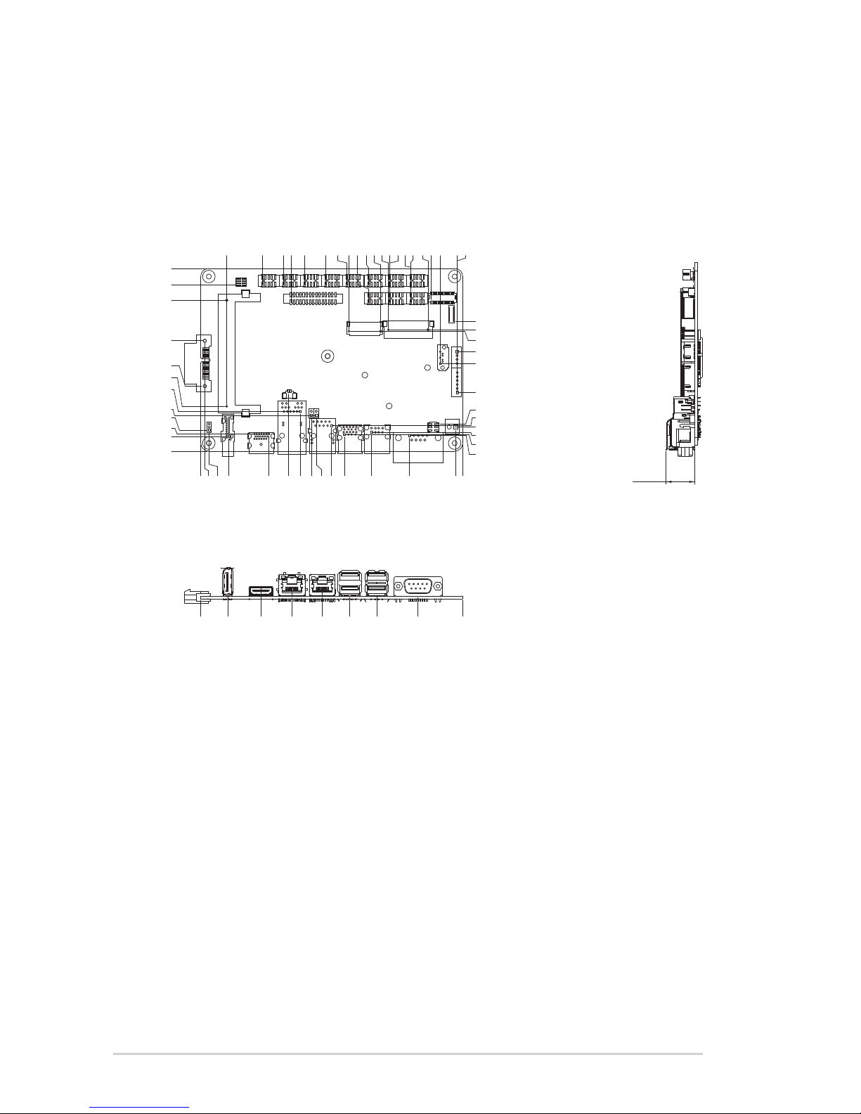
2.2 Motherboard layout
Place this side
towards the rear
of the chassis
NOTE: Placefourscrewsintotheholesindicatedbycirclestosecure
themotherboard to the chassis.
CAUTION!Donotovertightenthescrews!Doingsocandamagethe
motherboard.

2-3
Chapter 2: Motherboard information
Connectors/Jumpers/Slots Page
1. ClearRTCRAM(3-pinCLRTC1) 2-8
2. DDR3LSO-DIMMmemoryslot 2-6
3. PCIex1slot --
4. LVDS/EDPconnector(30-pinLVDSEDP) 2-14
5. BIOSprogrammingheaderforAaeon(8-pinSPI1) 2-14
6. Audioamplieranddigitalaudioconnector(10-pinSPDIF_AMP) 2-16
7. USB3.0connectors(10-pinUSB3_1,USB3_3) 2-15
8. LVDSpanelvoltageselection(10-pinLVDS_CTL) 2-9
9. Backlightinverterpowerconnectors(10-pinINV1,6-pinINV2) 2-17
10. DigitalI/Oconnector(10-pinDIO) 2-14
11. Frontpanelaudioconnector(10-pinAAFP) 2-12
12. Serialportconnectors(10-pinCOM2,COM34) 2-16
13. Systempanelconnector(10-pinF_PANEL1) 2-13
14. SIMcardconnector(10-pinSIM1) 2-11
15. CameraSerialInterfaceconnector(31-pinCSI1) 2-17
16. MainandstandbypowerLEDs(LED1,LED2) 2-1
17. SerialATA6.0Gb/sconnector(7-pinSATA6G1) 2-13
18. SATApowerconnector(4-pinSATA_PWR1) 2-12
19. COM1RI/+5V/+12Vselection(6-pinCOM1_V1) 2-9
20. 12VDCpowerconnector(2-pinDC_PWR) 2-11
21. MiniPCIex1slot(MINI_CARD1) 2-15
22. M.2E-keyconnector(2230_M2E) 2-18
23. InternalPOELANconnectors(2-pinJL1,JL2) 2-11
24. Batteryconnector(2-pinBATTERY1) 2-18
25. IntegratedIntel®processor 2-6
FAY-003
2-4
2.3 Screw size
2.3.1 Component side
115.00
0.00
40.89
28.17
69.49
94.97
13.11
9.21
10.75
24.99
22.48 16.04
15.19
10.49
11.84
9.85
36.93
62.68
54.97
76.45
75.45
5.23
0.00
2.50
17.75 16.28
42.75
62.58
55.15
82.41
56.77
38.70
52.03
65.37
78.70
92.04
105.63
119.09
105.63
118.96
132.30
93.34
113.34
118.24
143.24
69.62
72.80
90.50
107.50
131.46
160.46
150.80
161.57
161.44
132.43
104.44
145.05
17.11
81.61
18.30
17.10
0.00
38.00
57.50
76.70
94.00
111.00
137.00
165.00
165.00
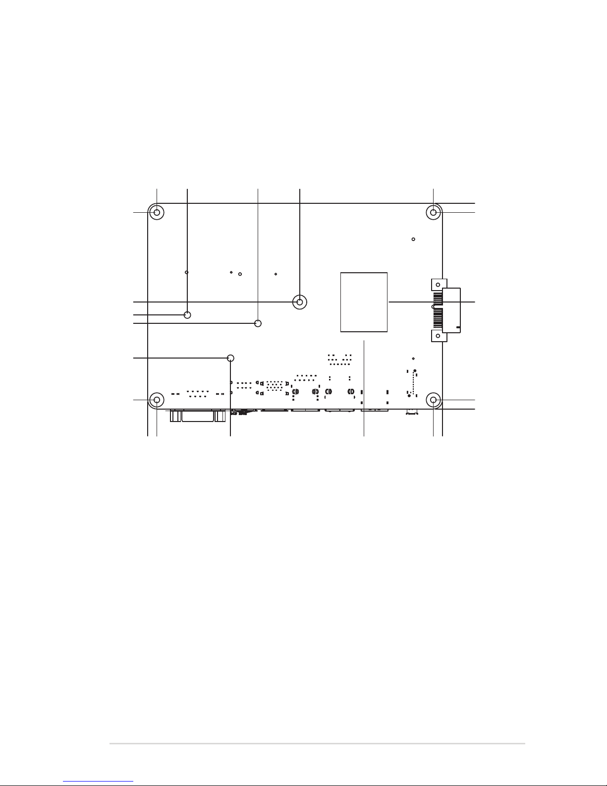
2-5
Chapter 2: Motherboard information
2.3.2 Solder side
5.07 0.00
28.40
47.85
52.55
59.77
109.92 109.92
5.08
59.77
5.08
0.00 5.08
159.92
159.92
118.64
142.84
103.34
79.91
43.93
115.00
165.00

FAY-003
2-6
2.4 Central Processing Unit (CPU)
ThismotherboardcomeswithanintegratedIntel®processor.
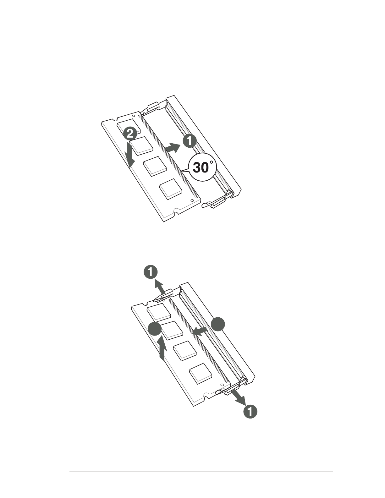
2.5 System memory
ThismotherboardcomeswithoneDoubleDataRate3LowVoltage(DDR3L)
SmallOutlineDualInlineMemoryModule(SO-DIMM)socket.Thegureillustrates
thelocationoftheDDR3LDIMMsocket:
FAY-003
FAY-003 CPU onboard
Integrated Intel®
processor
(Bottom)
FAY-003
FAY-003 204-pin DDR3L DIMM socket
DIMM_A1
2-7
Chapter 2: Motherboard information
Installing a DIMM
To install a SO-DIMM
To remove a SO-DIMM
3
2
3
2

FAY-003
2-8
2.6 Jumpers
1. Clear RTC RAM (3-pin CLRTC1)
ThisjumperallowsyoutocleartheRealTimeClock(RTC)RAMinCMOS.
YoucancleartheCMOSmemoryofsystemsetupparametersbyerasing
theCMOSRTCRAMdata.TheonboardbuttoncellbatterypowerstheRAM
datainCMOS,whichincludesystemsetupinformationsuchassystem
passwords.
To erase the RTC RAM:
1. Turn OFF the computer and unplug the power cord.
2. Movethejumpercapfrompins1-2(default)topins2-3.Keepthecapon
pins2-3forabout5~10seconds,thenmovethecapbacktopins1-2.
3. Plug the power cord and turn ON the computer.
4. Holddownthe<Del>keyduringthebootprocessandenterBIOSsetup
to reenter data.
CAUTION!ExceptwhenclearingtheRTCRAM,neverremovethecapon
CLRTCjumperdefaultposition.Removingthecapwillcausesystemboot
failure!
NOTES:
• Ifthestepsabovedonothelp,removetheonboardbatteryandmovethe
jumperagaintocleartheCMOSRTCRAMdata.AfterclearingtheCMOS,
reinstall the battery.
• YoudonotneedtocleartheRTCwhenthesystemhangsdueto
overclocking.Forsystemfailureduetooverclocking,usetheCPU
ParameterRecall(C.P.R)feature.Shutdownandrebootthesystemsothe
BIOScanautomaticallyresetparametersettingstodefaultvalues.
FAY-003
FAY-003 Clear RTC RAM
1 2 2 3
Normal operation
(Default)
Clear CMOS
CLRTC1

2-9
Chapter 2: Motherboard information
2. COM1 RI/+5V/+12V selector (6-pin COM1_V1)
3. LVDS panel voltage selection (10-pin LVDS_CTL)
Setting Pins
+12V 1-2
+5V 3-4
RI(Default) 5-6
Setting Pins
Set+V_PANELto+3V(Default) 2-4
SetLVDSbacklightcontroltoDC
mode(Default)
3-5
COM1_V1
5
6
3
4
1
2
+12V +5V RI
(Default)
FAY-003
FAY-003 COM1 RI/+5V/+12V selection
FAY-003
FAY-003 LVDS panel voltage selection
LVDS_CTL
+V_PANEL
+3V
LVDS_PWM
+3V_EPROM1
GND
+5V
BKLT_CTRL_VR1
VCON
EDID_CLK
EDID_DAT
PIN1
Pin 2-4: Set +V_PANEL to +3V (default)
Pin 3-5: Set LVDS backlight control to DC mode (default)

FAY-003
2-10
4. USB 3.0 port.This9-pinUniversalSerialBus(USB)portconnectstoUSB
3.0/2.0devices.
NOTES:
• USB3.0devicescanbeusedfordatastorageonly.
• DuetothedesignoftheIntel®300serieschipset,allUSBdevices
connectedtotheUSB2.0andUSB3.0portsarecontrolledbythexHCI
controller.SomelegacyUSBdevicesmustupdatetheirrmwareforbetter
compatibility.
• WestronglyrecommendthatyouconnectUSB3.0devicestoUSB3.0
portsforafasterandbetterperformancefromyourUSB3.0devices.
5. USB 2.0 ports.Thesethree4-pinUniversalSerialBus(USB)portsare
availableforconnectingUSB2.0/1.1devices.
6. COM port. This9-pinCOMportisforpointingdevicesorotherserialdevices
2.7 Connectors
2.7.1 Rear panel connectors
LAN port
Speed
LED
Activity Link
LED
31 2 54 6
1. DisplayPort connector. ThisportconnectsadevicewithDisplayPort
connector.
2. HDMI port.ThisportisforaHigh-DenitionMultimediaInterface(HDMI)
connector,andisHDCPcompliantallowingplaybackofHDDVD,Blu-Ray,
and other protected content.
3. LAN (RJ-45) ports.TheseportsallowGigabitconnectiontoaLocalArea
Network(LAN)throughanetworkhub.RefertothetablebelowfortheLAN
port LED indications.
LAN port LED indications
ACT/LINK LED SPEED LED
Status Description Status Description
Off No link Off 10Mbpsconnection
Orange Linked Orange 100Mbpsconnection
Orange
(Blinking)
Dataactivity Green 1Gbpsconnection
Orange
(Blinking
thensteady)
Readytowake
up from S5
mode
_ _

2-11
Chapter 2: Motherboard information
2.7.2 Internal connectors
1. 12V DC power connector (2-pin DC_PWR)
Thisportconnectstoa12VDCpoweradapter.
2. SIM card connector (10-pin SIM1)
ThisportconnectstoaSIMcardreadermodule.
FAY-003
FAY-003 12V DC power connector
PIN 1
GND
+12V
DC_PWR
FAY-003
FAY-003 Internal SIM card connector
UIM_CLK
UIM_RESET
UIM_PWR
NC
NC
UIM_DATA
UIM_VPP
GND
NC
NC
SIM1
Pin 1
JL1
PIN1
LAN1_VC3_20
LAN1_VC4_20
FAY-003
FAY-003 Internal POE LAN connectors
JL2
PIN1
LAN1_VC1_20
LAN1_VC2_20
3. Internal POE LAN connectors (2-pin JL1, JL2)
ConnectthePOELANpowercablestothisconnector.
Table of contents
Other Faytech Motherboard manuals


