Faytech Industrial Motherboard Series User manual

faytech
Industrial
Motherboard
Series
Industrial Motherboard

First Edition
June 2013
Copyright Notice
This document is copyrighted, 2013. All rights are reserved. The original
manufacturer reserves the right to make improvements to the products described
in this manual at any time without notice.
No part of this manual may be reproduced, copied, translated, or transmitted
in any form or by any means without the prior written permission of the original
manufacturer. Information provided in this manual is intended to be accurate and
reliable. However, the original manufacturer assumes no responsibility for its use,
or for any infringements upon the rights of third parties that may result from its use.
The material in this document is for product information only and is subject to
change without notice. While reasonable efforts have been made in the preparation
of this document to assure its accuracy, the original manufacturer assumes no
liabilities resulting from errors or omissions in this document, or from the use of the
information contained herein.
faytech reserves the right to make changes in the product design without notice to
its users.
Acknowledgments
All other products’ name or trademarks are properties of their respective owners.
•
•
•
•
•
AMI is a trademark of American Megatrends Inc.
Intel®, Core™ are trademarks of Intel®Corporation.
Microsoft Windows®is a registered trademark of Microsoft Corp.
ITE is a trademark of Integrated Technology Express, Inc.
IBM, PC/AT, PS/2, and VGA are trademarks of International Business
Machines Corporation.
faytech reserves the right to make changes in the product design without notice to
its users.
All other product names or trademarks are properties of their respective owners.
ii

BIOS setup
3.4
Advanced menu ............................................................................ 3-6
3.4.1
3.4.2
3.4.3
3.4.4
3.4.5
3.4.6
3.4.7
3.4.8
CPU Configuration ......................................................... 3-6
IDE Configuration ........................................................... 3-7
USB Configuration .......................................................... 3-7
APM ................................................................................ 3-7
Panel Controller (AMD®GPU only) ................................. 3-8
North Bridge LVDS Config Select (AMD®GPU only) ....... 3-8
Onboard Devices Configuration ...................................... 3-8
DIO Function ................................................................... 3-8
iii
Central Processing Unit (CPU) ..................................................... 2-6
System memory ............................................................................ 2-6
Jumpers ........................................................................................ 2-8
Connectors ................................................................................... 2-12
2.7.1
2.7.2
Rear panel connectors .................................................. 2-12
Internal connectors ........................................................ 2-13
Chapter 3:
3.1
3.2
3.3
BIOS setup program ..................................................................... 3-1
BIOS menu screen ....................................................................... 3-2
Main menu .................................................................................... 3-4
3.3.1
3.3.2
3.3.3
3.3.4
System Language [English] ........................................... 3-4
System Date [Day xx/xx/xxxx] ........................................ 3-4
System Time [xx:xx:xx] ................................................... 3-4
Security .......................................................................... 3-4
Contents
Chapter 1:
1.1
1.2
Package contents ......................................................................... 1-1
Specifications ................................................................................ 1-2
Before you proceed ....................................................................... 2-1
Motherboard layout ....................................................................... 2-2
Screw size ..................................................................................... 2-4
2.3.1
2.3.2
Component side ............................................................. 2-4
Solder side ..................................................................... 2-5
Features ........................................................................................ 1-1
Product overview
1.3
2.1
Chapter 2:
2.2
2.3
Motherboard information
2.4
2.5
2.6
2.7

Contents
3.5
Monitor menu ................................................................................. 3-9
3.5.1
3.5.2
3.5.3
3.6
3.5.4
3.6.1
3.6.2
3.6.3
3.6.4
3.7
3.8
3.6.5
CPU Temperature / MB Temperature [xxxºC/xxxºF] ....... 3-9
Chassis Fan Speed [xxxx RPM] or [N/A] ........................ 3-9
Chassis Q-Fan Control [Enabled] ................................... 3-10
CPU Voltage, 3.3V Voltage, 5V Voltage, 12V Voltage .... 3-10
Bootup NumLock State [On] ........................................... 3-10
Full Screen Logo [Disabled] ............................................ 3-11
Wait for ‘F1’ If Error [Enabled] ......................................... 3-11
Boot Option Priorities ...................................................... 3-11
Boot Override .................................................................. 3-11
Boot menu ...................................................................................... 3-10
Tools menu ..................................................................................... 3-11
Exit menu ....................................................................................... 3-12
Appendix
Notices ........................................................................................................ A-1
iv

Product overview
1.1
Package contents
Motherboard heatink/ cooler optional
Cable Kit
DVD-ROM for manual (in PDF format) and drivers
NOTE: If any of the above items are damaged or missing, contact your
distributor or sales representative immediately.
Check your industrial motherboard package for the following items.
1.2
•
•
•
•
•
•
•
•
•
•
Features
Integrated Intel®Atom™ processor N2600 / N2800 (optional)
Realtek®ALC887, Audio Amplifier EUA 2012A
Dual Ethernet LAN: Realtek®8111F x 2
SATA 3Gb/s x 2, USB2.0 x 6, COM x 4
One Single Channel DDR3 800 / 1066MHz SO-DIMM Up To 2GB
Multi Display: LVDS+HDMI, VGA+LVDS, VGA+HDMI
2 x Mini Card slots with PCIe and USB interface (1 x Full Height with SIM card
interface, 1 x Half Height, 1 x PCIe 1 x slot)
EuP/ErP Compliance
AMD®HD7410M (optional)
PCIx1 Straddle
Chapter 1: General information
1-1
Chapter 1
1.3
CPU
Memory
Chipset
I/O Chipset
LAN
Audio
Specifications
SYSTEM
Integrated Intel Atom™ processor N2600 / N2800 (optional)
®
1 x SO-DIMM, max. 2GB, DDR3 800 / 1066MHz, non-ECC, un-buffered
Memory (max. 4GB for N2800)
Single channel memory architecture
Intel®NM10
Fintek 81866D-I
2 x Realtek®8111F PCIe Gigabit LAN controllers
1 x Audio Amplifier EUA 2012A
1 x Realtek®ALC887 8-channel high definition audio CODEC
2 x Mini Card slots with PCIe and USB interface (1 x Full Height with SIM
card interface, 1 x Half Height), 1 x PCIe 1 x slot
Expansion slot
BIOS
H/W Status Monitor
Watchdog Timer
Smart Fan Control
Wake On LAN / PXE
Power States
Graphics Chipset
Graphics Multi Display
Resolution
LVDS Inverter Control
Battery
Power requirement
Power compliance
Operating
temperature
Operating humidity
Form factor
EMI
64Mb Flash ROM, UEFI AMI BIOS, PnP, DMI 2.0, Wfm 2.0, SM BIOS, ACPI
3.06
Monitors CPU/system temperature
Monitors chassis fan speed
Yes
Yes ( WOL, PXE)
S3, S4, S5
®
Monitors Vcore, 3.3V/5V/12V voltages
1~255 steps by software program
AMD HD7410M with 512M memory (optional)
LVDS+HDMI, VGA+LVDS, VGA+HDMI
VGA: Up to 1920 x 1200 @60Hz (optional)
HDMI: Up to 1920 x 1200 @60Hz
LVDS: Up to 2048 x 1536 @60Hz, 24 bit dual channel
Graphics
Environment, Power, and ME
Lithium battery
1 x DC connector on rear I/O
Compliant with Eup/ErP
14oF~131oF (-10oC~55oC)
0%~90% relative humidity, non-condensing
EPIC form factor: 4.53 in. x 6.5 in. (11.5 cm x 16.5 cm)
CE, FCC
1 x onboard 2-pin power connector
(continued on the next page)
1-2
faytech Motherboard
Voltage / PWM, 1 x DC 5V/12V for LCD backlight inverter board
Storage
USB
Display I/O
Audio I/O
LAN I/O
Serial port
PS/2 port
DIO
Fan
RTC
I/O
2 x SATA 3Gb/s ports
6 x USB 2.0 ports (2 ports at mid-board, 4 ports on rear I/O)
1 x LVDS connector, 1 x VGA connector, 1 x HDMI port
Mic-In, Line-Out, S/PDIF onboard headers
Amplifier onboard header
HDMI support audio
2 x RJ-45 ports on rear I/O
1 x 5V/12V RS232/RS485 port on rear I/O (COM1)
1 x PS/2 keyboard / mouse connector
8-bit Digital I/O interface (4-in/4-out)
1 x Chassis fan connector (4-pin)
Internal RTC
3 x RS232 onboard headers (COM2, COM3, COM4)
Back panel I/O ports 1 x HDMI port
I/O Placement
1 x COM port (RS232/485)
2 x LAN (RJ-45) port
4 x USB 2.0 ports
Internal I/O
connectors
1 x Lockable DC power port (12V)
1 x VGA pin header
1 x 12V DC power connector (2-pin)
2 x SATA 3Gb/s connectors
1 x 4-pin SATA power connector
1 x PS/2 keyboard/mouse connector (6-pin)
3 x RS232 COM connectors
1 x LVDS connector
1 x USB 2.0 header supports additional 2 USB 2.0 ports
1 x 5-pin LCD power connector
1 x Full Height Mini Card slot
1 x SIM card connector
1 x Half Height Mini Card slot
1 x 4-pin audio amplifier connector
1 x S/PDIF output pin header
1 x DIO connector
1 x PCIeX1 Straddle
1 x Line-Out / Mic-In audio pin header (AAFP)
(continued on the next page)
Chapter 1: General information
1-3

Others
Supported OS
Windows®XP 32-bit
Windows®7 32-bit
Windows®8 32-bit
Linux Fedora
Windows®XP 64-bit (only with AMD graphics)
Windows®7 64-bit (only with AMD graphics)
Windows®8 64-bit (only with AMD graphics)
Accessories
1 x SATA 3Gb/s cable
1 x SATA power cable
1 x Support DVD (Drivers, Manual)
NOTE: Specifications are subject to change without notice.
1-4
faytech Motherboard

Chapter 2
2.1
Motherboard information
Before you proceed
Take note of the following precautions before you install motherboard components
or change any motherboard settings.
CAUTION!
•
•
Unplug the power cord from the wall socket before touching any
component.
Before handling components, use a grounded wrist strap or touch a safely
grounded object or a metal object, such as the power supply case, to avoid
damaging them due to static electricity.
Hold components by the edges to avoid touching the ICs on them.
Whenever you uninstall any component, place it on a grounded antistatic
pad or in the bag that came with the component.
Before you install or remove any component, ensure that the power supply
is switched off or the power cord is detached from the power supply. Failure
to do so may cause severe damage to the motherboard, peripherals, or
components.
•
•
•
Chapter 2: Motherboard information
2-1
11
12
13
14
9
SATA_PWR1
DDR3 DIMM_A1
DC_PWR
EATX_PWR1
CHA_FAN1
Place this side towards
the rear of the chassis
19
18
17 16
COM3
COM4
J1
15
2-2
faytech Motherboard
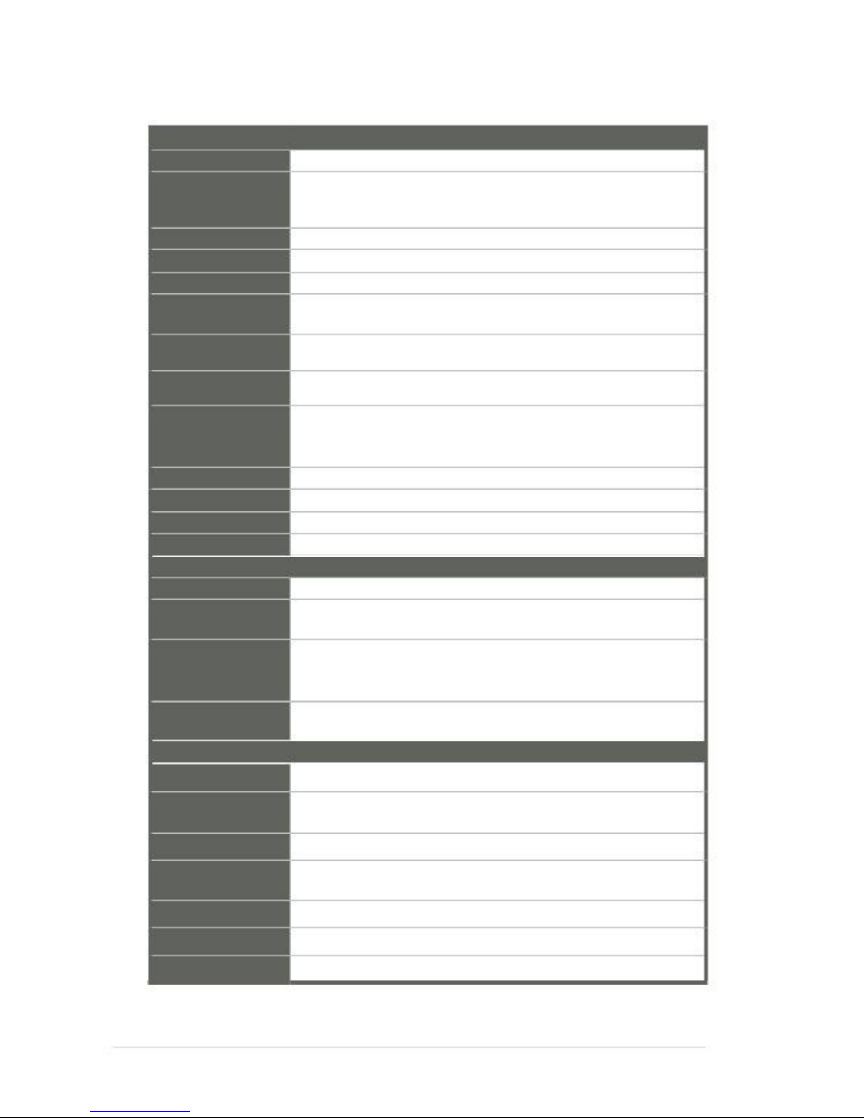
2.2
Motherboard layout
NOTE: Place five screws into the holes indicated by circles to secure the
motherboard to the chassis.
CAUTION! Do not overtighten the screws! Doing so can damage the
motherboard.
1
2
PCIeX1
3
11.5cm(4.53in)
AAFP1
4
5
AMP_CON1
SPEAKER
SPDIF_OUT1
HDMI1
ALC
887
MINI_CARD1
SPI1
SIM1
ICS
9VRS4339AL
SATA3G_2
SATA3G_1
ISD72
D9MGG
6
7
AMD®
HD7410M
LAN1
RTL
8111F
AMD®
GPU (optional)
PEX8605
ISD72
D9MGG
MINI_CARD2
PLX
LAN2
USB2
RTL
8111F
Intel®
NM10
R560
010S LVDS1
16.5cm(6.5i
n)
DIO1
COM2
COM1
J2
N2600
BATTERY
LVDS_VDD_SEL1CLRTC
1
24
23
22
21
20
Super
I/O
Intel®
F_PANEL1
INV1
KBMS1
LCD_POWER_SEL1L_B
RIGHTNESS1
25
USB3
USB1
26
VGA
8
10

Connectors/Jumpers/Slots
1. Digital audio connector (4-1 pin SPDIF_OUT1)
2. Line-Out / Mic-In audio connector (10-1 pin AAFP1)
3. SPI programming connector (8-pin SPI1)
4. Audio amplifier connector (4-pin AMP_CON1)
5. Serial ATA 3Gb/s connectors (7-pin SATA3G_1/2)
6. Internal speaker connector (4-pin SPEAKER)
7. LVDS connector (30-pin LVDS1)
8. VGA connector (16-pin VGA)
9. LCD inverter power setting jumper (3-pin LCD_POWER_SEL1)
10. LVDS backlight brightness control jumper (3-pin L_BRIGHTNESS1)
11. Backlight inverter power connector (5-pin INV1)
12. System panel connector (10-1 pin F_PANEL1)
13. Digital I/O connector (10-pin DIO1)
14. Serial port connectors (9-pin COM2/3/4)
15. Chassis fan connector (4-pin CHA_FAN1)
16. Clear RTC RAM (3-pin CLRTC1)
17. LVDS panel VDD setting jumper (3-pin LVDS_VDD_SEL1)
18. PCIeX1 Straddle
19. EATX power connector (2-pin EATX_PWR1) 12V, DC-IN (1: + 2: GND)
20. Lockable DC power port (DC_PWR) 12V, DC-IN
21. SATA power connector (4-pin SATA_PWR1)
22. COM1 Ring and voltage selection (6-pin J1)
23. Battery connector (2-pin BATTERY)
24. AT Mode selection (2-pin J2)
25. PS/2 keyboard/mouse connector (6-pin KBMS1)
26. USB 2.0 connector (10-pin USB1)
Page
2-13
2-13
2-18
2-20
2-17
2-15
2-21
2-20
2-11
2-10
2-19
2-16
2-22
2-14
2-15
2-8
2-10
2-6
2-14
2-12
2-17
2-9
2-21
2-9
2-19
2-18
NOTES:
•
•
If your motherboard has an onboard AMD®GPU, you should install the
display driver.
If your motherboard does not have an onboard AMD®GPU, you should
install the VGA driver.
Chapter 2: Motherboard information
2-3
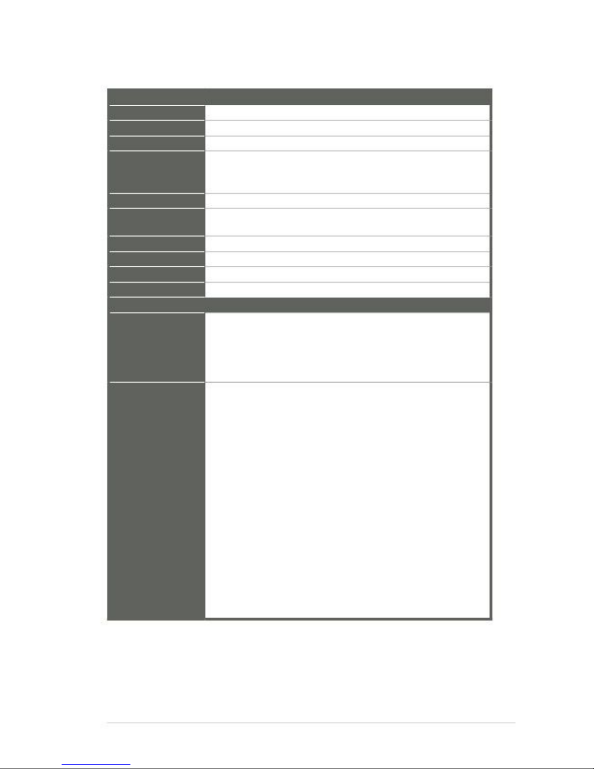
2.3
2.3.1
Screw size
Component side
2-4
faytech Motherboard
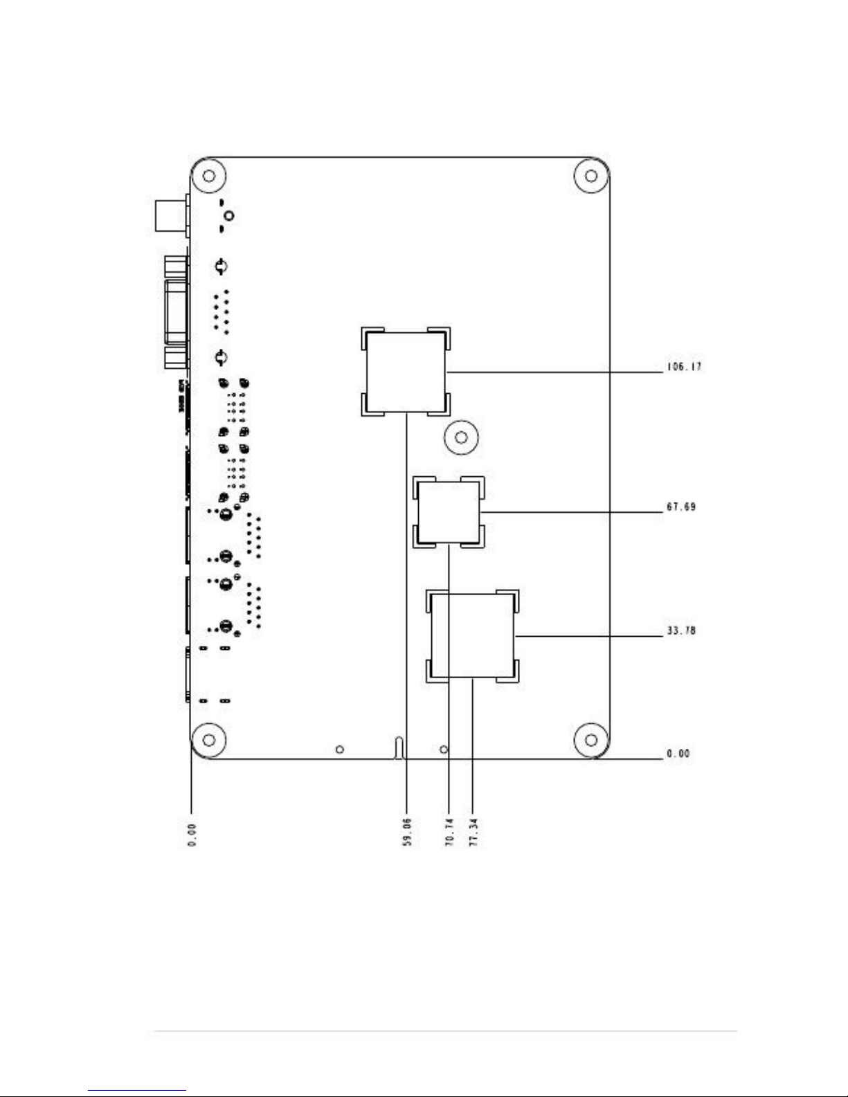
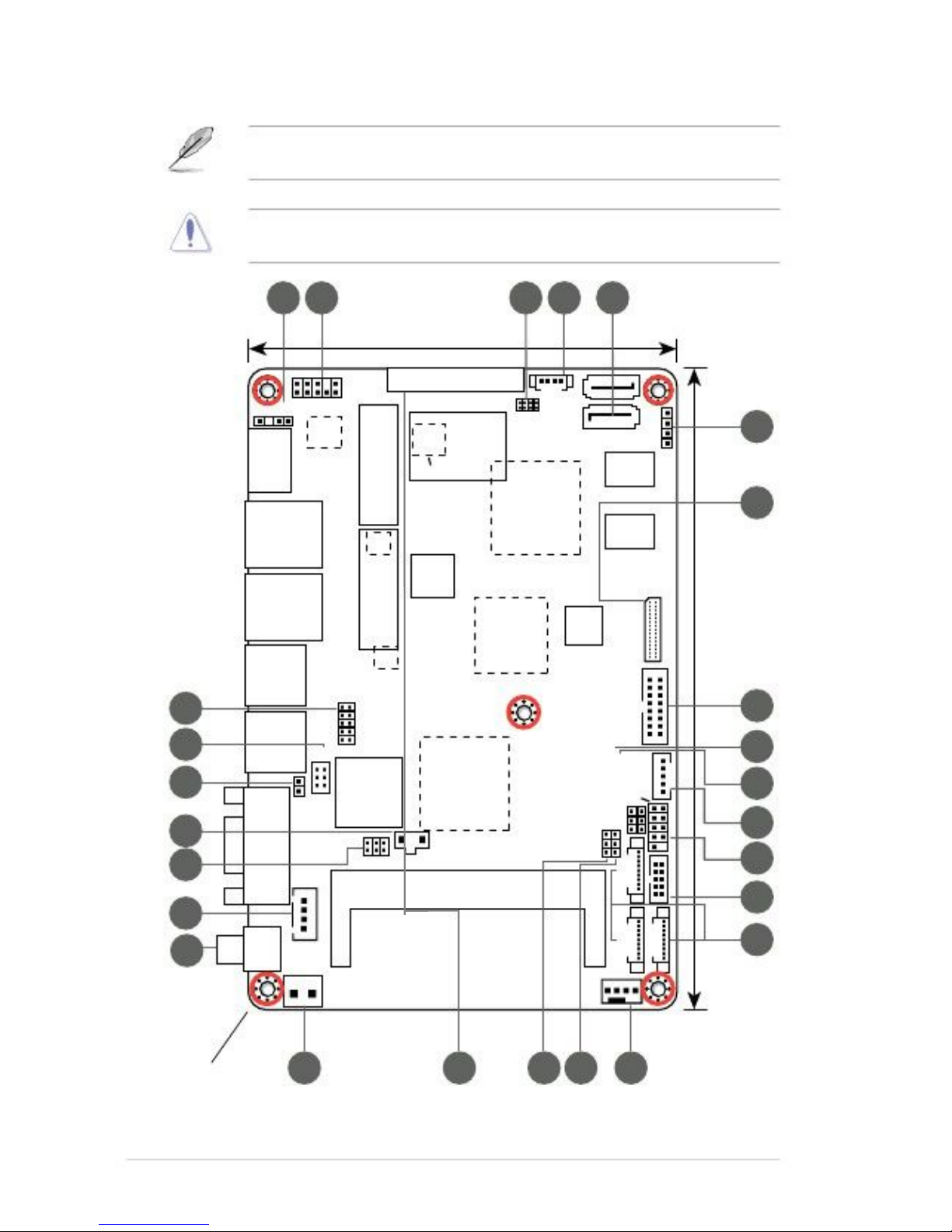
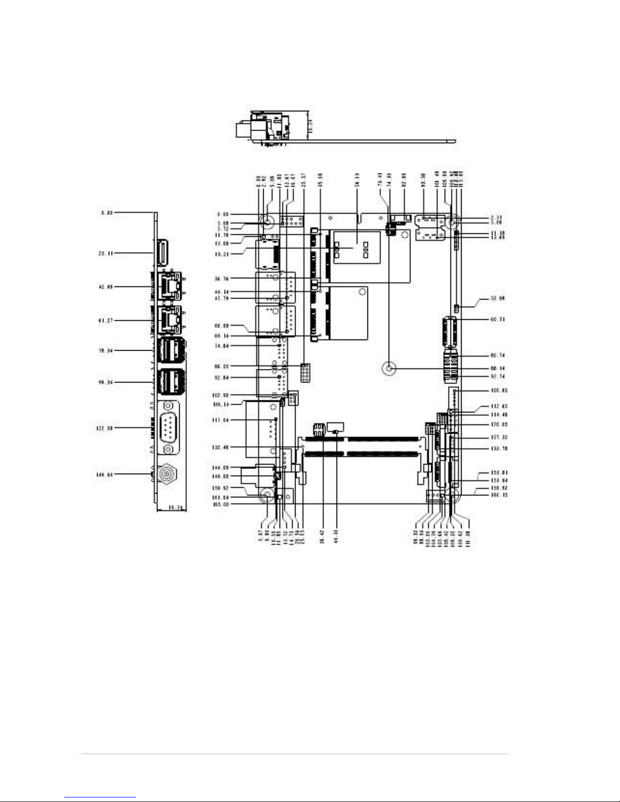
2.3.2
Solder side
Chapter 2: Motherboard information
2-5

2.4
Central Processing Unit (CPU)
The motherboard comes with an integrated Intel®Atom™ processor N2600 /
N2800 (optional).
Integrated Intel®
Atom™ processor
faytech Industrial Motherboard Series Integrated Intel®Atom™ processor
2.5
System memory
This motherboard comes with one Double Data Rate 3 (DDR3) Small Outline Dual
Inline Memory Modules (SO-DIMM) socket. The figure illustrates the location of the
DDR3 DIMM socket:
DIMM_A1
faytech Industrial Motherboard Series DDR3 DIMM socket
faytech Industrial Motherboard Series
PCIxe1 Straddle
3
2-6
faytech Motherboard
faytech Industrial Motherboard Series Integrated Intel®Atom™ processor
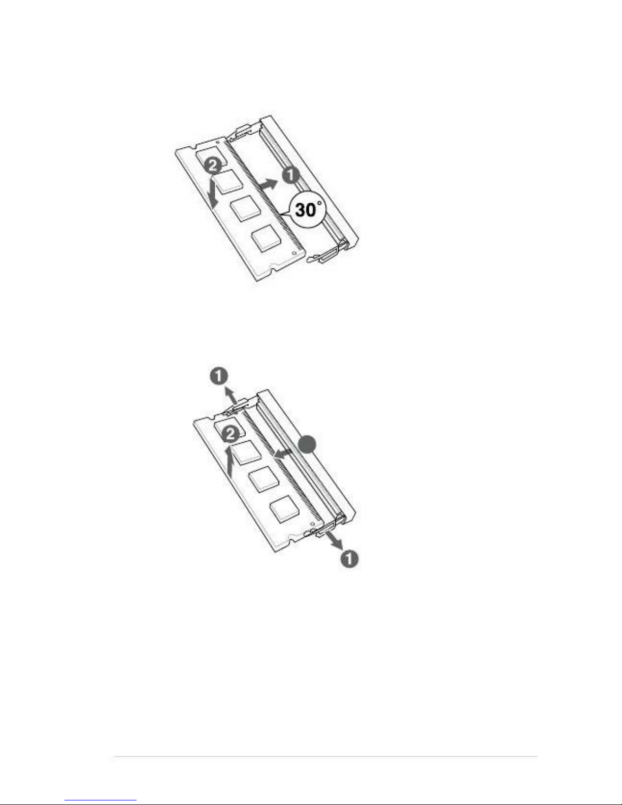
To install a DIMM
To remove a DIMM
3
Chapter 2: Motherboard information
2-7

2.6
1.
This jumper allows you to clear the Real Time Clock (RTC) RAM in
CMOS. You can clear the CMOS memory of date, time, and system setup
parameters by erasing the CMOS RTC RAM data. The onboard button
cell battery powers the RAM data in CMOS, which include system setup
information such as system passwords.
Clear RTC RAM (3-pin CLRTC1)
Jumpers
CLRTC1
2
1
2
Normal
(Default)
Clear
faytech Industrial Motherboard Series Clear CMOS RAM
To erase the RTC RAM:
1.
2.
3.
4.
Turn OFF the computer and unplug the power cord.
Move the jumper cap from pins 1-2 (default) to pins 2-3. Keep the cap on
pins 2-3 for about 5~10 seconds, then move the cap back to pins 1-2.
Plug the power cord and turn ON the computer.
Hold down the <Del> key during the boot process and enter BIOS setup
to reenter data.
CAUTION! Except when clearing the RTC RAM, never remove the cap on
CLRTC jumper default position. Removing the cap will cause system boot
failure!
NOTES:
•
If the steps above do not help, remove the onboard battery and move the
jumper again to clear the CMOS RTC RAM data. After clearing the CMOS,
reinstall the battery.
You do not need to clear the RTC when the system hangs due to
overclocking. For system failure due to overclocking, use the CPU
Parameter Recall (C.P.R) feature. Shut down and reboot the system so the
BIOS can automatically reset parameter settings to default values.
•
3
2-8
faytech Motherboard
2.
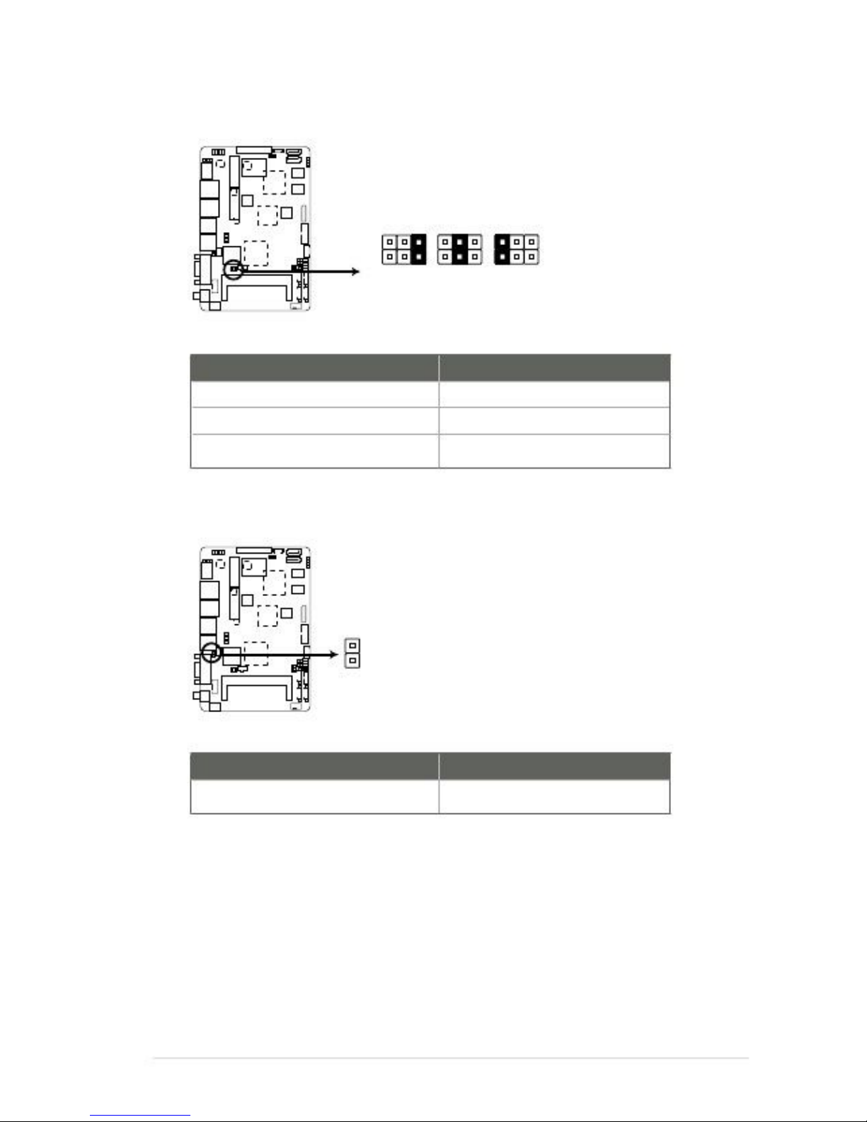
COM1 Ring and voltage selection (6-pin J1)
J1
1
2
3
4
5
6
+12V
+5V
Ring
(Default)
faytech Industrial Motherboard Series COM1 Ring and voltage selection
Pins
1-2
3-4
5-6
+12V
+5V
Ring (Default)
3.
AT Mode selection (2-pin J2)
J2
PIN1
AT MODE
faytech Industrial Motherboard Series AT Mode selection
Pins
1-2
AT Mode
Chapter 2: Motherboard information
2-9

4.
LVDS backlight brightness control jumper (3-pin L_BRIGHTNESS1)
L_BRIGHTNESS1
2
1
DC MODE
(Default)
PWM MODE
faytech Industrial Motherboard Series LVDS backlight brightness control jumper
Pins
1-2
2-3
DC Mode (Default)
PWM Mode
5.
LVDS panel VDD setting jumper (3-pin LVDS_VDD_SEL1)
LVDS_VDD_SEL1
2
1
2
+3V
+5V
(Default)
faytech Industrial Motherboard Series LVDS panel VDD setting jumper
Pins
1-2
2-3
+3V
+5V (Default)
3
2-10
faytech Motherboard

6.
LCD inverter power setting jumper (3-pin LCD_POWER_SEL1)
LCD_POWER_SEL1
2
1
2
+12V
(Default)
+5V
faytech Industrial Motherboard Series LCD inverter power setting jumper
Pins
1-2
2-3
+12V (Default)
+5V
Chapter 2: Motherboard information
3
2-11
2.7
2.7.1
Connectors
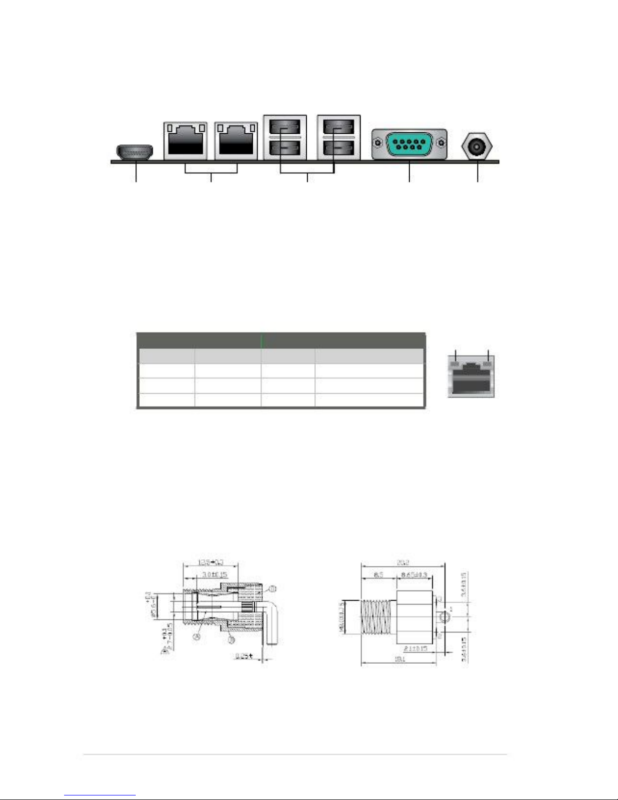
Rear panel connectors
1
1.
2.
2
3
4
5
LAN (RJ-45) ports. These ports allow Gigabit connection to a Local Area
Network (LAN) through a network hub. Refer to the table below for the LAN
port LED indications.
LAN port LED indications
ACT/LINK LED StatusDescription
OFFNo link
ORANGE Linked
BLINKING Data activity
SPEED LED StatusDescription
OFF10 Mbps connection
ORANGE 100 Mbps connection
GREEN1 Gbps connection
Activity
Link LED
Speed
LED
HDMI port. This port is for a High-Definition Multimedia Interface (HDMI)
connector, and is HDCP compliant allowing playback of HD DVD, Blu-Ray,
and other protected content.
LAN port
3.
4.
5.
COM port. This 9-pin COM1 port is for pointing devices or other serial
devices.
USB 2.0 ports. These two 12-pin Universal Serial Bus (USB) ports are
available for connecting USB 2.0/1.1 devices.
Lockable DC power port (+12V). This port connects to a DC power adapter.
To select the correct power adapter, refer to the inner and outer dimensions
of this power port.
2-12
faytech Motherboard
Table of contents
Other Faytech Motherboard manuals


Popular Motherboard manuals by other brands


STMicroelectronics
STMicroelectronics STEVAL-GLA001V1 user manual

ECS
ECS B75H2-M2 user manual

Gigabyte
Gigabyte GA-G41M-ES2L user manual

NXP Semiconductors
NXP Semiconductors LPC55S06-EVK quick start guide

Diamond Systems
Diamond Systems Rhodeus-LC LX800 PC/104 user manual

Advantech
Advantech AIMB-213 user manual


