FC Curtis NX Series User manual
CAP-835
June, 2018
Rev. E
WARNING
Personal injury and/or equipment damage will be result by failing to pay attention to the vital safety
information and instructions in this manual. Carefully read, understand, and retain all safety information and
instructions before operating this compressor.
NX Series
Oil –Injected Rotary Screw Compressor
Operator Manual
18 –185 kW (25 –250 HP)

CAP-835 3
Information on these operating instructions
These instructions enable you to use the
machine safely and efficiently. The instructions
are a component part of the machine and must
be accessible for staff at all times.
Staff must have carefully read and understood
these instructions before starting all work. The
basic prerequisite for safe working is compliance
with all the safety instructions and instruction for
actions included in these operating instructions.
The local occupational health and safety
regulations and general safety rules for
operational area of the machine also apply.
The instructions for the machine do not cover
operation of the controller. Therefore, the
instructions and content of the instructions for
the controller in question must also be taken into
account.
Copyright
These instructions are protected by copyright
and for internal purposes only.
These instructions must not be made available
to third parties, reproduced in any way -
even excerpts - and the content must not be
utilized and/or communicated, except for internal
purposes, without the written permission of the
manufacturer.
Any infringement shall be subject to
compensation for damages. We reserve the
right to assert further claims.
Limitation of liability
All information and instructions in this manual
have been compiled taking account of the
applicable standards and regulations, state-of-
the-art technology and our years of knowledge
and experience.
The manufacturer assumes no liability for
damages caused by:
◼failure to adhere to these instructions
◼improper use
◼use of unqualified staff
◼unauthorized conversions
◼technical modifications
◼use of non-approved spare parts
The actual scope of supply may differ from the
descriptions and illustrations in these
instructions in the case of special designs, the
inclusion of additional ordering options or as a
result of the latest technical modifications.
The obligations agreed in the contract of supply,
the manufacturer's general terms and conditions
of business and delivery and the legal
regulations valid at the time of completion of the
contract apply.
Technical Service
Our Technical Service department is available to
provide technical information.
In addition, our employees are always interested
in receiving new information and hearing of your
experiences from usage which could be valuable
for the improvement of our products.
Safety
It is assumed that your safety department will
have established a program of safety based
upon a thorough analysis of industrial hazards.
Before installing and operating or performing
maintenance on the equipment described in this
instruction book, it is suggested that you again
review this program to be certain that it covers
the hazards arising from high speed rotating
machinery.
It is also important that due consideration be
given to those hazards which arise from the
presence of electrical power, hot oil, high
pressure and temperature, steam, toxic gases
and flammable liquids and gases. Proper
installation and care of protective guards,
shutdown devices and over-pressure protection
should also be considered essential parts of any
safety program.
CAP-835
4
1Safety..........................................................................................................................................................................................6
1.1 Symbols in these instructions...........................................................................................................................................6
1.2 Proper use.......................................................................................................................................................................7
1.3 Safety devices.................................................................................................................................................................8
1.3.1 Position of the safety devices ....................................................................................................................................9
1.3.2 Description of the installed safety devices .................................................................................................................9
1.4 Environmental protection ...............................................................................................................................................10
1.5 Signage.........................................................................................................................................................................10
2Transportation, packaging and storage..................................................................................................................................12
2.1 Safety instructions for transportation..............................................................................................................................12
2.2 Inspection on receipt of delivery.....................................................................................................................................12
2.3 Packaging......................................................................................................................................................................12
2.4 Symbols on the packaging.............................................................................................................................................12
2.5 Transportation ...............................................................................................................................................................13
2.6 Storage..........................................................................................................................................................................13
3Installation and commissioning..............................................................................................................................................14
3.1 Safety instructions for the installation and commissioning..............................................................................................14
3.2 Requirements in the installation location........................................................................................................................15
3.3 Installation.....................................................................................................................................................................15
3.3.1 Remove shipping spacers .......................................................................................................................................15
3.3.2 Ventilation ...............................................................................................................................................................15
3.3.3 Connection to the compressed air network..............................................................................................................16
3.3.4 Connecting to the power supply...............................................................................................................................16
3.4 Checking the oil level.....................................................................................................................................................17
3.5 Start-up lubrication of the compressor airend.................................................................................................................17
3.6 Switching on after installation.........................................................................................................................................18
3.7 Work after the initial commissioning...............................................................................................................................18
4Design and function.................................................................................................................................................................20
4.1 Overview .......................................................................................................................................................................20
4.2 Brief description.............................................................................................................................................................24
4.3 Assembly description.....................................................................................................................................................24
4.3.1 Enclosure doors ......................................................................................................................................................24
4.3.2 Screw Compressor..................................................................................................................................................24
4.3.2.1 Drive unit.................................................................................................................................................................24
4.3.2.1.1 Screw compressor with V-belt drive ....................................................................................................................25
4.3.2.1.2 Screw compressor with direct drive.....................................................................................................................25
4.3.3 Intake filter...............................................................................................................................................................25
4.3.4 Compressor airend..................................................................................................................................................25
4.3.5 Oil separator tank....................................................................................................................................................26
4.3.6 Air/oil separator.......................................................................................................................................................26
4.3.7 Minimum pressure and non-return valve..................................................................................................................27
4.3.8 Coolers....................................................................................................................................................................27
4.3.9 Oil filter....................................................................................................................................................................28
4.3.10 Cooling air fan.........................................................................................................................................................28
4.4 Interfaces.......................................................................................................................................................................29

CAP-835 5
5Technical data..........................................................................................................................................................................30
5.1 Serial tag.......................................................................................................................................................................30
5.2 General specifications....................................................................................................................................................31
5.2.1 Operating conditions................................................................................................................................................31
5.2.2 Oil............................................................................................................................................................................31
5.2.3 Oil Capacity.............................................................................................................................................................31
6Operation..................................................................................................................................................................................32
6.1 Safety instructions for operation.....................................................................................................................................32
6.2 Modulation Control.........................................................................................................................................................32
7Maintenance.............................................................................................................................................................................33
7.1 Environmental protection ...............................................................................................................................................33
7.2 Spare parts....................................................................................................................................................................33
7.3 Maintenance schedule...................................................................................................................................................33
7.4 Service kits....................................................................................................................................................................34
7.5 Maintenance work..........................................................................................................................................................36
7.5.1 Checking for leaks...................................................................................................................................................36
7.5.2 Checking the electrical connections.........................................................................................................................36
7.5.3 Checking the oil level/topping up the oil...................................................................................................................36
7.5.4 Checking the build-up of condensation....................................................................................................................37
7.5.5 Checking the compressor temperature....................................................................................................................38
7.5.6 Inspect/clean coolers...............................................................................................................................................38
7.5.7 Checking the drive unit............................................................................................................................................38
7.5.8 Re-lubricating the electric motor ..............................................................................................................................38
7.5.9 Replacing the oil/changing the oil filter.....................................................................................................................39
7.5.10 Replacing the air/oil separator.................................................................................................................................40
7.5.10.1 Spin on/off separator style.......................................................................................................................................40
7.5.10.2 Drop in style separator............................................................................................................................................40
7.5.11 Replacing the intake filter ........................................................................................................................................40
7.6 Clean/replace return line................................................................................................................................................41
7.7 Measures after maintenance has been performed.........................................................................................................41
8Faults........................................................................................................................................................................................42
8.1 Safety instructions for fault clearance.............................................................................................................................42
8.2 Fault displays.................................................................................................................................................................43
8.3 Troubleshooting.............................................................................................................................................................44
8.4 Work for fault clearance.................................................................................................................................................45
8.5 Commissioning after remedied fault...............................................................................................................................45
9Index .........................................................................................................................................................................................46
10 Appendix...................................................................................................................................................................................47
10.1 Bolt tightening torque requirements................................................................................................................................47
10.2 Oil change intervals at elevated temparatures................................................................................................................47

CAP-835
6
1 Safety
This section is a summary of important safety
aspects to ensure optimum protection of the
personnel and safe and trouble-free operation.
The owner, lessor or operator of this com-
pressor is hereby notified and forewarned
that failure to observe these safety
precautions may result in injury and/or
property damage.
FS Curtis does not mean to imply that the
following safety precautions are all-inclusive or
that the observance of these precautions will
prevent all injury or property damage.
FS Curtis expressly disclaims responsibility or
liability for any injury or property damage caused
by failure to follow these specified precautions or
by failure to exercise ordinary caution and due
care required in operating or handling this
equipment even though not expressly specified.
1. Read and understand all the instructions
found in this manual before operating your
compressor.
2. Disconnect the main power source before
working on or performing any maintenance
procedures on this unit. Use a lock out and
tag out process.
3. Do not attempt to remove any parts, break
any connection, loosen oil fill plug or drain
plug until the unit has been shut down and
air pressure has been relieved.
4. Do not operate the compressor in excess of
its rated pressures and speeds indicated on
the compressor nameplate.
5. Do not remove guards, shields, or screens
while the compressor is in operation. If
removed for maintenance replace before
resuming operation.
6. Observe the delivery pressure gauge daily
to be sure the automatic control system is
operating within proper limits.
7. Periodically check all safety and relief
devices for proper operation.
8. Use compressed air properly. Pressurized
air can cause serious injury to personnel.
9. Be sure that no tools, rags or loose parts are
left in or on the compressor or drive parts.
10. Do not use flammable solvents for cleaning
parts.
11. Exercise cleanliness during maintenance
and when making repairs. Keep dirt away
from parts and exposed openings by
covering with clean rags or plastic to prevent
cross contamination.
12. Do not install a shut-off valve in the
discharge line without installing a pressure
relief valve between the shut-off and the
compressor package.
13. Do not operate the compressor in areas
where there is a possibility of flammable or
toxic substances entering the system.
14. Never disconnect (or jump) the air discharge
temperature switch or any other safety
device and attempt to operate the
compressor.
15. Know what state of operation the
compressor is in before working around the
unit. The power may be on and the machine
not running if it is in the auto restart mode.
Adhere to note #2 above.
16. Make sure to follow the local electrical and
environmental code requirements in your
area to ensure compliance prior to installing
the compressor.
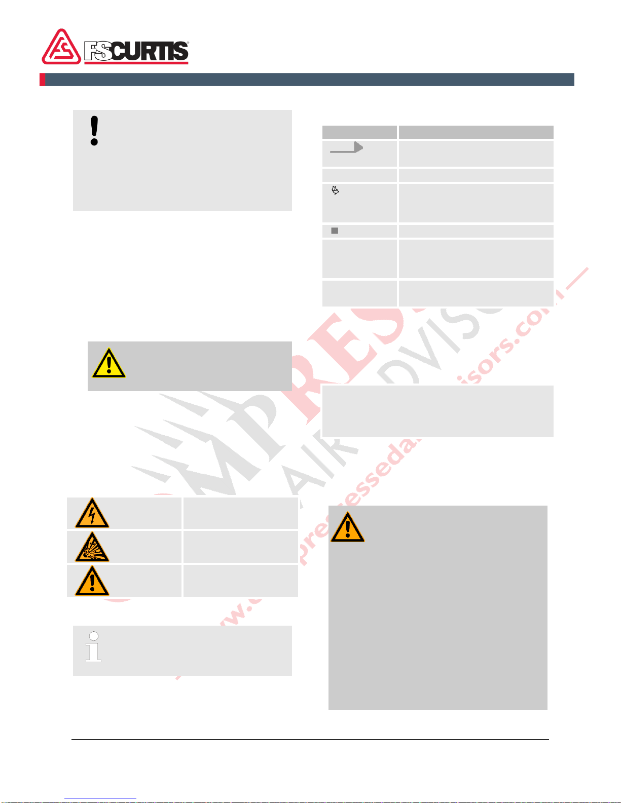
1.1 Symbols in these instructions
Safety instructions
The safety instructions and safety information in
these instructions are denoted by symbols. The
safety instructions are prefaced by signal words
which express the extent of the risk.
DANGER!
This combination of symbol and
signal word indicates a direct
hazardous situation which will lead to
serious or even fatal injuries if not
avoided.
WARNING!
This combination of symbol and
signal word indicates a possibly
hazardous situation which may lead
to serious or even fatal injuries if not
avoided.
CAUTION!
This combination of symbol and
signal word indicates a possibly
hazardous situation which may cause
minor or light injuries if not avoided.
CAP-835 7
NOTICE!
This combination of symbol and
signal word indicates a possibly
hazardous situation which may
cause material damage if not
avoided or possible hazards for the
environment.
Safety instructions in action sequences
Safety instructions may relate to certain,
individual instructions for actions. These safety
instructions are embedded in the instruction for
action so that they do not interrupt the flow of
reading when performing the action. The signal
words described above are used.
Example:
1.
Unfasten the screw.
2.
CAUTION!
Risk of entrapment on the
cover!
Close the cover carefully.
3.
Tighten the screw.
Special safety instructions
The following symbols are used in conjunction
with the safety instructions in order to draw
attention to particular hazards:
Warning –high-
voltage.
Warning –explosive
substances.
Warning –danger
zone.
Tips and recommendations
This symbol indicates tips and
recommendations and information
for efficient and fault-free operation.
Further markings
The following markings are used in these
instructions for emphasizing instructions for
actions, results, lists, cross references and other
elements:
Marking
Explanation
Step-by-step instructions for
actions
Results of actions
References to sections of these
instructions and other
applicable documents
Lists without a set order
[Button]
Operating controls (e.g.
buttons, switches), display
elements (e.g. indicator lamps)
"Display"
Screen elements (e.g. buttons,
assignment of function keys)
1.2 Proper use
The machine is designed and constructed
exclusively for the proper use described here.
Do not operate the compressor in excess of
its rated pressures, operating conditions,
and speeds indicated on the compressor
nameplate.
The proper use also includes adherence to all
details in this manual.
Any use beyond the proper use or other type of
use counts as misuse.
WARNING!
Danger due to misuse!
- The compressed air may not be
used for breathing without
appropriate after-treatment.
- The compressed air may not be
used directly for the handling of
food without appropriate after-
treatment.
- The screw compressor may not
be operated outdoors.
- The screw compressor or
individual components may not
be rebuilt, modified or re-
equipped.
CAP-835
8
Claims of any type for damage due to misuse
are excluded.
1.3 Safety devices
WARNING!
Danger to life from nonfunctional
safety devices!
If safety devices are not functioning
or are disabled, there is a danger of
injury or death.
- Check that all safety devices are
fully functional and correctly
installed before starting work.
- Never disable or bypass safety
devices.
- Ensure that all safety devices
are always accessible.
CAP-835 9
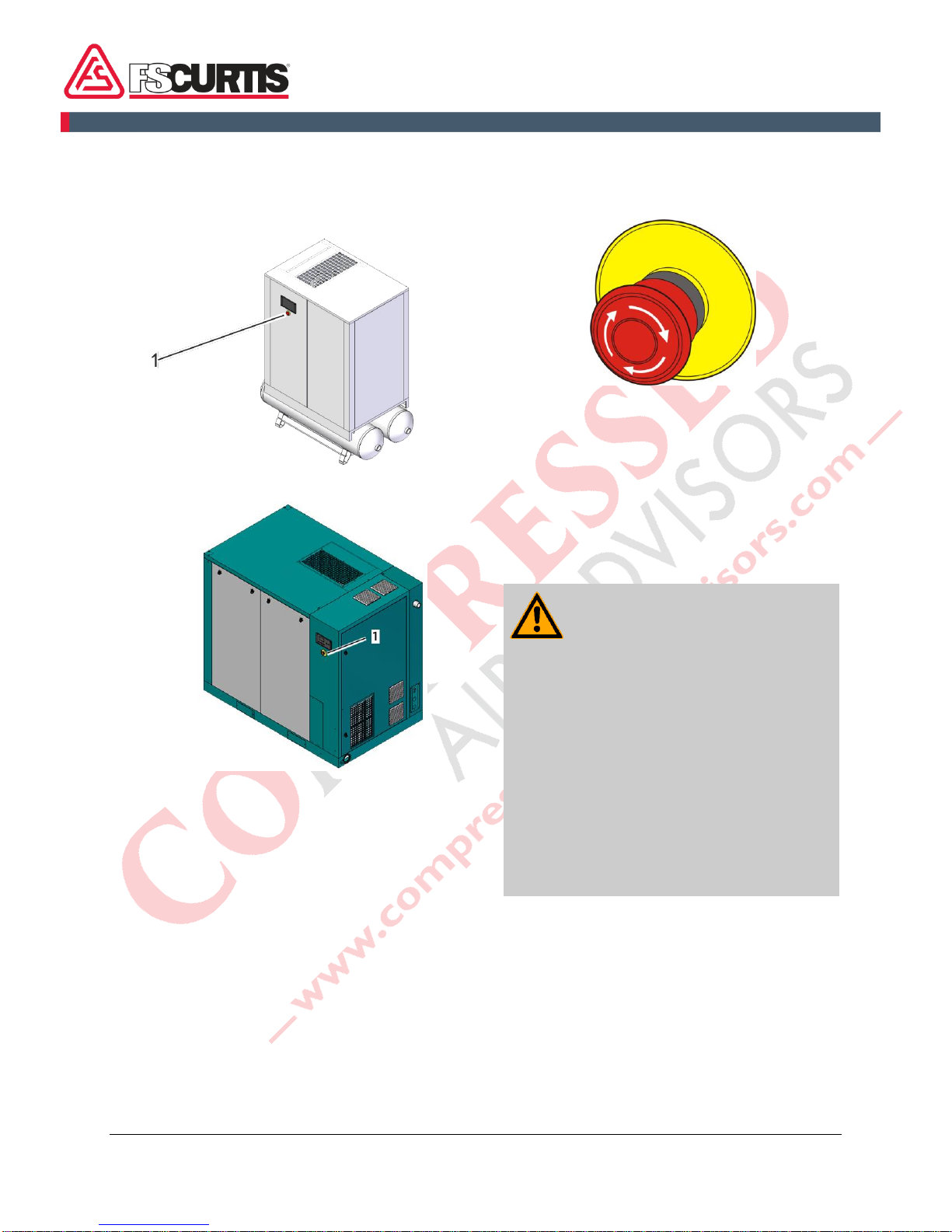
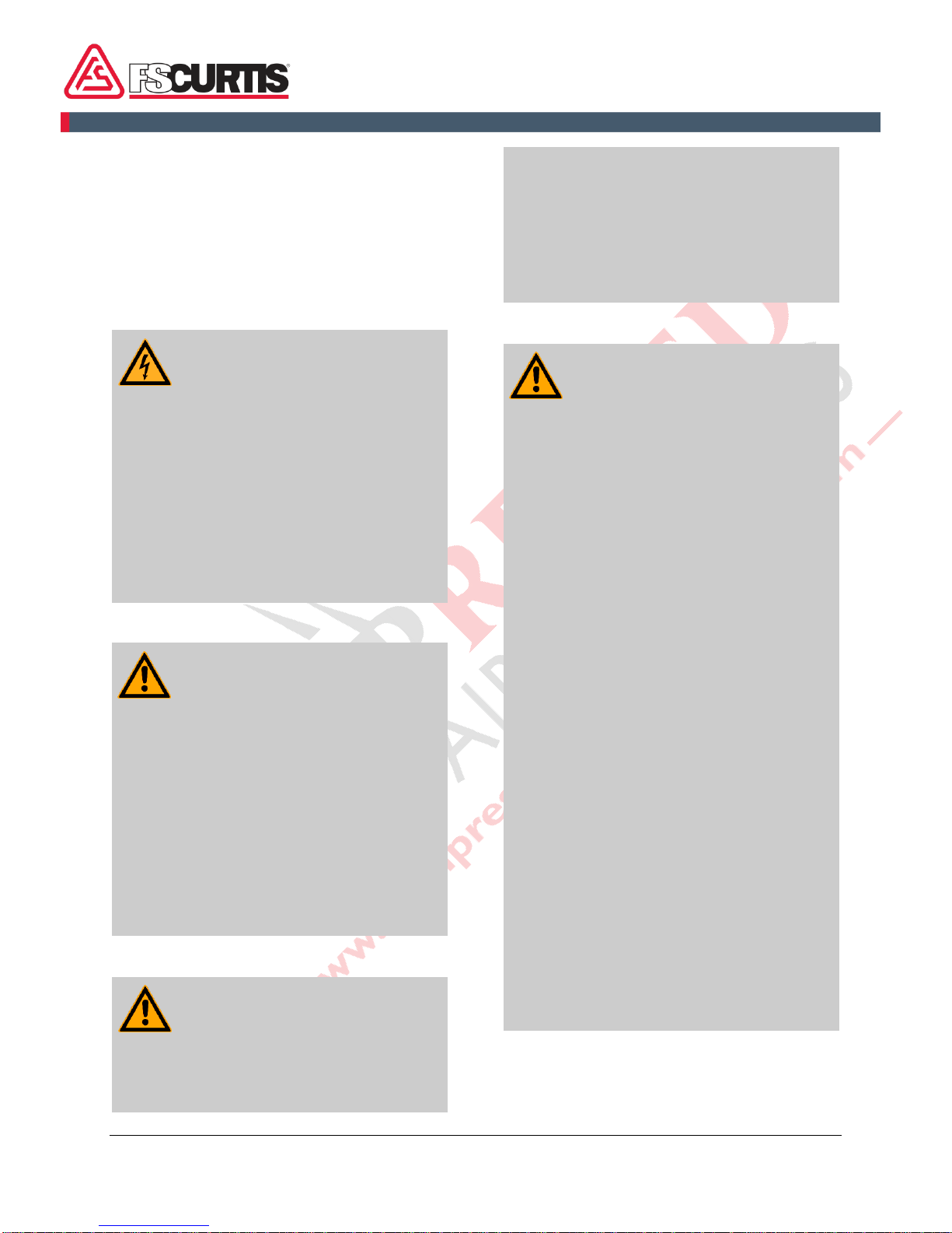
1.3.1 Position of the safety
devices
The following illustrations show the position of
the safety devices.
Fig. 1: Emergency stop button (Fig.1-1) on the screw
compressor 18–37 kW with tank (optional)
Fig. 2: Emergency stop button (Fig.2-1) on the screw
compressor 45–185 kW
1.3.2 Description of the installed
safety devices
Emergency stop button
Fig. 3: Emergency stop button
By pressing the emergency stop button, the
machine is stopped by an immediate switching
off of the compressor. After the emergency stop
button has been pressed, it must be unlocked by
turning it so that the button is released. The
controller fault must be reset. Refer to the
controller documentation for information on
fault displays.
WARNING!
Danger to life from an
unauthorized restart!
An uncontrolled restart of the
machine may cause serious injuries
including death.
- Before switching the machine
back on, make sure the cause of
the emergency stop has been
removed and all safety devices
have been installed and function
properly.
- Do not unlock the
EMERGENCY-STOP button
until there is no more danger.
Relief valves
Relief valves are unburdening equipment for
areas under pressure such as pressure vessels
and pipes. In case of an impermissible pressure
increase, relief valves bleed off gases, vapors or
liquids into the atmosphere.

CAP-835
10
Fig.4: Pressure Relief Valve
Do not change the pressure setting of the
pressure relief valve, restrict the function of
the relief valve or replace the relief valve with
a plug.
1.4 Environmental protection
NOTICE!
Danger to the environment from
incorrect handling of pollutants!
Incorrect handling of pollutants,
particularly incorrect waste disposal,
may cause serious damage to the
environment.
- Always observe the instructions
below regarding handling and
disposal of pollutants.
- Take the appropriate actions
immediately if pollutants escape
accidentally into the
environment. If in doubt, inform
the responsible municipal
authorities about the damage
and ask about the appropriate
actions to be taken.
The following chemicals are used:
Oil
Oils can contain substances that are harmful to
the environment. They must not be allowed to
escape into the environment. Store oils in
suitable containers and dispose of in
accordance with applicable local, state and
federal regulations
Lubricants
Lubricants such as greases and oils can contain
harmful substances. They must not be allowed
to escape into the environment. Dispose of
lubricants in accordance with applicable local,
state and federal regulations.
1.5 Signage
WARNING!
Danger of injury from illegible
symbols!
Stickers and signs can become dirty
or otherwise obscured over time,
with the result that dangers cannot
be recognized and the necessary
operating instructions cannot be
complied with. This, in turn, poses a
risk of injury.
- All safety, warning and operating
instructions must always be
maintained in a completely
legible condition.
- Damaged signs or stickers must
be replaced immediately.
Direction of rotation
There is a direction of rotation sticker on the
drive unit and on the cooling air ventilator. This
sticker shows the appropriate direction of
rotation.
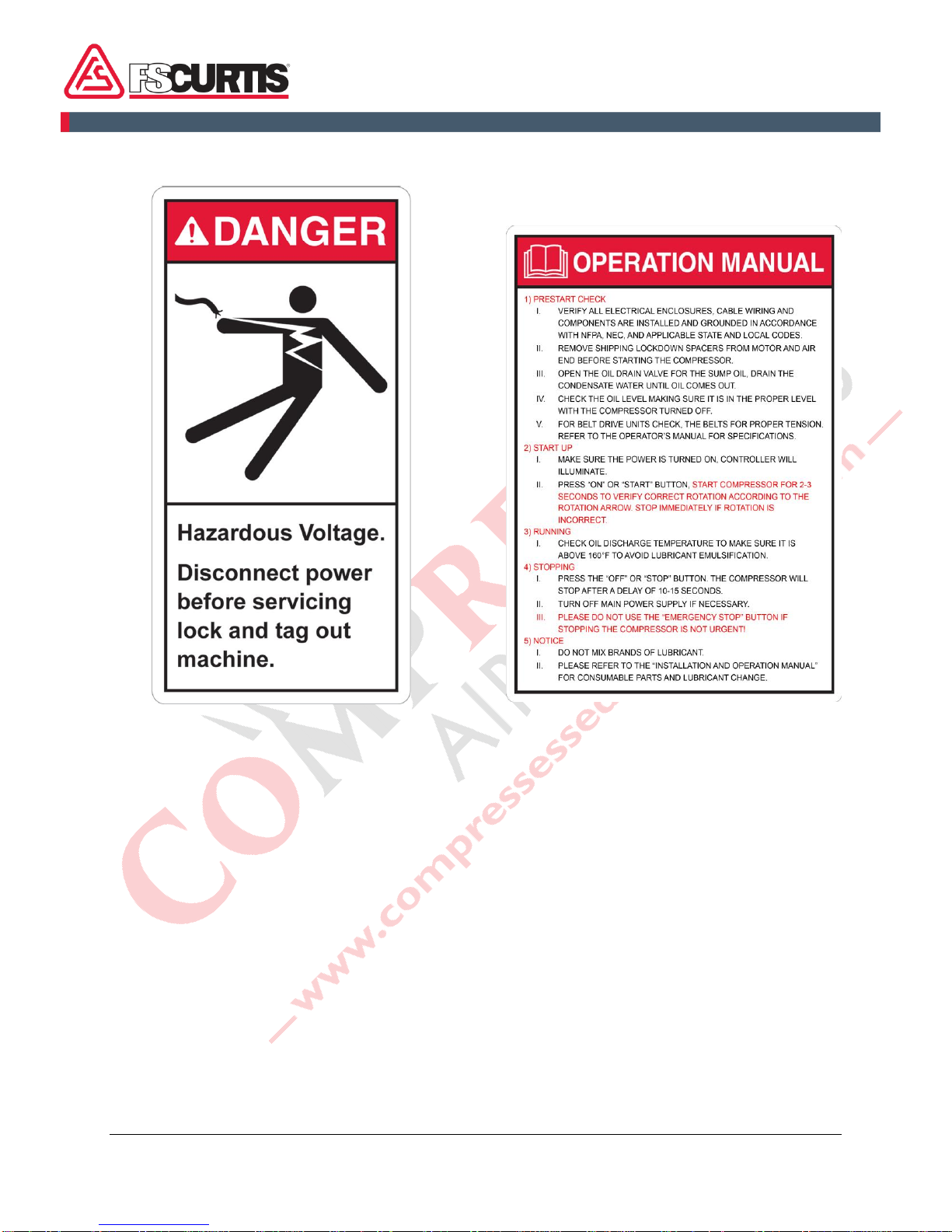
CAP-835 11
Hazardous Voltage Brief instructions for operation
This sticker is on the enclosure and contains
brief instructions for operation.

CAP-835
12
2 Transportation, packaging and storage
2.1 Safety instructions for
transportation
Improper transport
NOTICE!
Damage to property due to
improper transport!
Air compressors may fall or tip over
as a result of improper transport.
This can cause a significant level of
property damage.
- Proceed carefully when
unloading compressor units at
delivery and during in-house
transport; observe the symbols
and instructions on the
packaging.
- Only use the attachment points
provided.
- Only remove the packaging
shortly before assembly.
2.2 Inspection on receipt of
delivery
On receipt, immediately inspect the delivery for
completeness and transport damage.
Proceed as follows in the event of externally
apparent transport damage:
◼Do not accept the delivery, or only accept it
subject to reservation.
◼Note the extent of the damage on the
transport documentation or the shipper's
delivery note.
◼Initiate complaint procedures.
Issue a complaint in respect of each
defect immediately following
detection. Damage compensation
claims can only be asserted within
the applicable complaint deadlines.
2.3 Packaging
About the packaging
The individual screw compressors are packaged
in cartons or sometimes on wooden frames and
according to the anticipated transport conditions.
Only environmentally-friendly materials are used
for the packaging.
The packaging should protect the individual
components against transport damage,
corrosion and other damage until assembly.
Therefore, do not destroy the packaging and
only remove it shortly before assembly.
Handling packaging materials
Dispose of packaging material in accordance
with the relevant applicable legal requirements
and local, state and federal regulations.
2.4 Symbols on the packaging
The following symbols can be on the packaging.
Always heed these symbols during transport.
Top
The arrow tips on the sign mark the top of the
package. They must always point upwards;
otherwise the content could be damaged.
Fragile
Marks packages with fragile or sensitive
contents.
Handle the package with care; do not allow to
fall and do not expose to impacts.
CAP-835 13
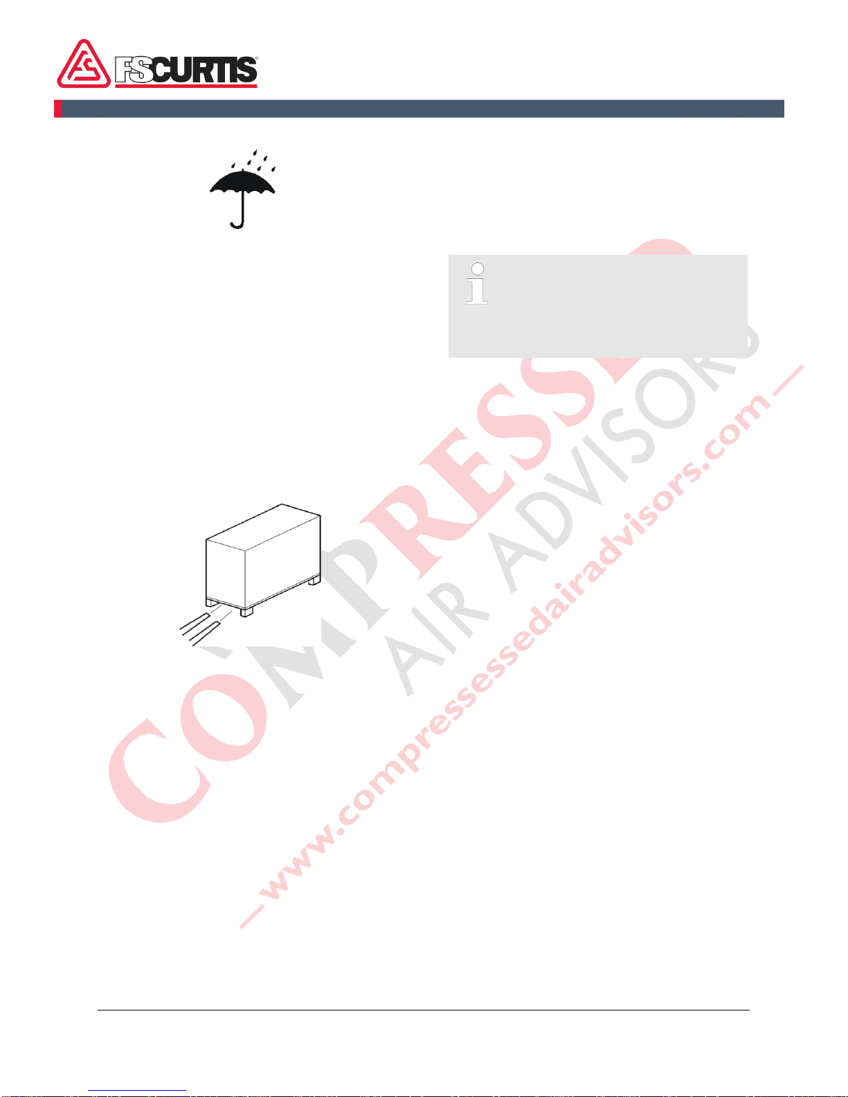
Protect against moisture
Protect packages against moisture and keep
dry.
2.5 Transportation
Transportation with a fork lift
Packages can be transported with a fork lift
under the following conditions:
◼The fork lift must be engineered for the
weight of the packages.
◼Existing guide rails on the frame must be
used.
◼The length of the forks must be at least 55
inch (1400 mm).
Transporting
Fig. 5: Transportation with a fork lift
1.
Drive the fork lift with the forks as shown in
Fig. 5.
2.
Insert the forks so that they stick out on the
other side.
3.
Ensure that the package cannot tip if the
centre of gravity if off-centre.
4.
Lift the package and begin transportation.
2.6 Storage
Storage of the packaged compressor
Store the compressor under the following
conditions:
◼Do not store outdoors.
◼Store dry and dust-free.
◼Do not expose to any aggressive media.
◼Protect against solar radiation.
◼Avoid mechanical jolts.
◼Storage temperature: 60 to 95F (15 to 35
°C).
◼Relative humidity: max. 60 %.
◼In case of storage for longer than 3 months,
check the general condition of all parts and
the packaging regularly. If necessary, refresh
or replace the rust-proofing.
Under some circumstances there
may be notes about storage on the
packaging that extend beyond the
requirements named here. Adhere
to these accordingly.
◼Extended storage: Rotate the compressor
and motor by hand every thirty to sixty days
to prevent flat spots on the bearings that can
lead to premature failure.
CAP-835
14
3 Installation and
commissioning
3.1 Safety instructions for the
installation and
commissioning
Electrical system
DANGER!
Danger to life from electric
power!
Contact with live parts may prove
fatal. When switched on, electric
components can be subject to
uncontrolled movements and may
cause grave injury or death.
- Switch off the power supply
before starting work and make
sure that it cannot be switched
on again. Follow lockout/ tagout
procedure.
Improper initial commissioning
WARNING!
Danger of injury due to improper
initial commissioning!
Improper initial commissioning can
result in serious injury and
significant damage to property.
- Before the initial commissioning,
ensure that all installation work
has been carried out and
completed in accordance with
the information and instructions
in this manual, National Electric
Code, and local state and
federal regulations.
Securing to prevent restart
WARNING!
Danger to life from an
unauthorized restart!
In the event of an unauthorized
restart of the power supply during
installation, there is a danger of
serious injuries or death for persons
in the danger zone.
- Switch off all power supplies
before starting work and make
sure they cannot be switched on
again. Follow lockout/ tagout
procedure.
Improper installation and commissioning
WARNING!
Risk of injury due to improper
installation or commissioning!
Improperly performed installation
and commissioning may lead to
serious injury and significant
material damage.
- Provide for sufficient mounting
clearance before starting to
work.
- Use caution when handling
exposed components with sharp
edges.
- Keep the assembly area tidy and
clean! Loose components and
tools lying around or on top of
each other may lead to
accidents.
- Mount all components properly.
Tighten all screws to the
prescribed torque.
- Secure components to prevent
them from falling down or tipping
over.
- Observe the following prior to
commissioning:
- make sure that all installation
work has been performed
and completed following the
instructions and information
provided in this manual.
- make sure that no persons
are still in the danger zone of
the machine.

CAP-835 15
3.2 Requirements in the
installation location
Set up the screw compressor so that the
following conditions are fulfilled:
◼The installation location is level.
◼The machine is easily accessible and can be
accessed from all sides.
◼There is sufficient lighting.
◼There is sufficient ventilation.
◼There is a power supply available.
◼Escape paths and rescue equipment are
freely accessible.
◼The machine is not subjected to an explosive
atmosphere.
◼The machine is not subjected to a corrosive
atmosphere.
◼The machine is not subjected to direct solar
radiation.
◼Outside heating from surrounding heat
sources is excluded.
◼There is no dust accumulation.
◼Fire protection measures have been taken.
◼The machine is not subjected to vibrations.
◼The floor is resistant to solvents,
impermeable to liquids, anti-static and easy
to clean.
◼There are no machines in the vicinity that
cause electrical or electromagnetic
disturbance.
3.3 Installation
3.3.1 Remove shipping spacers
To protect the vibration isolators underneath the
motor/airend assembly during transport, there
are red spacers that hold the assembly in place.
Make sure all of these spacers are removed
before first startup of the compressor. Failure
to remove the spacers will result in excessive
vibration and can cause damage to the
compressor.
Fig.6 : Shipping spacer
3.3.2 Ventilation
DANGER!
Risk of fatal injury from the use
of explosive gas mixtures,
vapors, dust or aggressive
hazardous substances!
The use of explosive gas mixtures,
vapors, dust or aggressive
hazardous substances to ventilate
the screw compressor can cause
severe or even fatal injuries as well
as significant material damage.
- Never use explosive gas
mixtures, vapors, dust or
aggressive hazardous
substances to ventilate the
screw compressor.
- Make sure that no potentially
explosive gas mixtures, vapors,
dust or aggressive hazardous
substances enter into the
ventilation for the screw
compressor.
The air fed via the intake openings is used for
compression and for cooling the machine.

CAP-835
16
NOTICE!
Risk of material damage from
condensation!
Cooling air with moisture content
can cause condensation.
- Make sure that the cooling air is
cool, dry and free of dust.
1.
Provide the required rate of cooling air as per
the technical data sheet for the screw
compressor.
2.
Extract the exhaust air as per the technical
data sheet for the screw compressor.
This prevents the installation room and the
screw compressor from heating up.
3.3.3 Connection to the
compressed air network
WARNING!
Danger of injury due to
unpredictable movement of the
compressed air hose!
Load switches in the compressed
air network causes jerky
movements of the compressed air
hose with high force.
- Anchor and fasten the
compressed air hose sufficiently.
The prerequisite for the correct
installation is the presence of a
professionally-planned, installed
and maintained compressed air
network and an additional shut-off
valve installed at the entrance to the
compressed air network.Relief
valves are to be placed ahead of
any potential blockage point,
including but not limited to shut-off
valves, heat exchangers and
discharge silencers.Always direct
discharge from relief valves away
from areas where personnel may
be.
FSC base mounted compressor packages come
with a mounted starter. Ensuring that the starter
is mounted per national and local NEL
requirements, it’s responsibility of the owner.
1.
Connect the compressed air.
2.
Ensure that the compressed air connection
does not represent a stumbling hazard.
3.
Anchor and fasten the compressed air
connection sufficiently.
Air piping requirements:
1. Install required accessories.
2. Main piping should have 1˚- 2˚ slant away
from the compressor to drain the condensate.
3. Pressure drop of piping must not exceed 5%
of discharge pressure. Select larger piping than
required for better efficiency.
4. Branch line must be located at the topside of
main piping to avoid condensate from flowing
into the facilities.
5. To prolong service life of pneumatic tools,
install an air filter regulator unit on the outlet.
6. Do not randomly reduce the size of the main
piping. If necessary, use the proper
reducer or a large pressure loss may incur .
7. The common installation arrangement is; air
compressor + air tank + dryer. An air tank is
capable of draining some of the condensate and
cooling down the temperature of compressed
air. This will lead to more efficient dryer opera-
tion.
8. If the air requirement is large for a short peri-
od, install a higher volume air tank to reduce the
frequency of full/off load control.
9. The ideal piping main would be constructed
around the factory as a loop for delivering com-
pressed air from both sides at any point.
3.3.4 Connecting to the power
supply
Personnel:
◼Qualified Electrician
NOTICE!
Property damage to the
compressor airend due to
incorrect connection of the power
supply!
In case of incorrect connection of
the power supply, there is a danger
that the compressor airend will be

CAP-835 17
destroyed due to the drive turning
incorrectly.
- Connect the power according to
the wiring diagram and check the
airend and motor for correct
rotation before starting the
compressor.
The prerequisite for the correct
installation are professionally sized
fuses in the network supply
(person/system protection) and an
appropriate main switch (for switching
the supply on and off).
1.
Using the data in the wiring diagram, check
whether the existing supply network is
suitable. Voltage deviations of more than
10% are not permitted.
2.
Connect the power according to the wiring
diagram.
3.
Check correct direction of rotation by briefly
starting the compressor and verifying that the
rotation of the machine follows the arrows on
the main motor and fan motor.
4.
Ensure that the power cable does not
represent a stumbling hazard.
5.
Select the correct wire diameter according to
the rated power of the air compressor. Do not
use wire diameter that is too small, or power
cord will be easily burnt out and generate
danger.
6.
Avoid use with other systems with different
power consumption in parallel. If it is used in
parallel, excessive voltage drop or three-
phase current unbalance will result in electri-
cal overload and the protective devices will
shut down the machine.
7.
Power supply cable, fuse and air-break
switch need to match the compressor power
supply requirements to ensure the safety of
all electrical components.
8.
It is necessary to confirm the correct voltage
while performing power distribution of the air
compressor.
9.
The grounding wire of a motor or system
must be reliably installed and grounding wire
cannot be connected to air delivery pipe or
cooling water pipe. Air compressor must be
reliably grounded to prevent danger from
electrical leakage.
10.
Ensure that the power supply is shut off be-
fore any electrical maintenance work. Use
lockout tag out.
3.4 Checking the oil level
1.
Switch the compressor off and secure it to
prevent it from being switched back on
again.
2.
Open and remove the enclosure panels with
the special wrench.
Fig. 7: Inspection glass
3.
Check the inspection glass (Fig. 7-1) to make
sure the oil is between the top and bottom oil
level indicator lines.
4.
If necessary, top up oil
Chapter 7.5.9
‘Replacing the oil/changing the oil filter’ on
page 39.
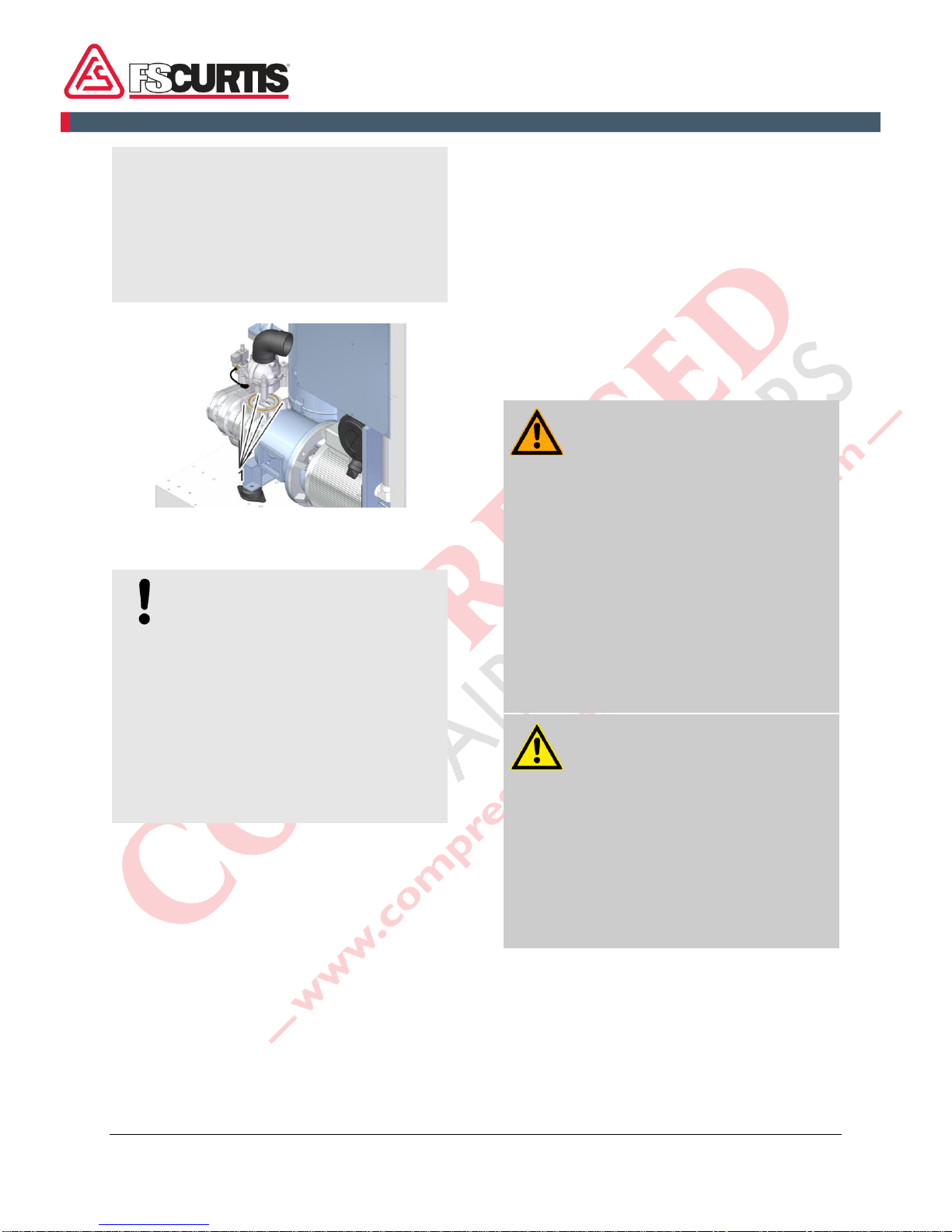
3.5 Start-up lubrication of the
compressor airend
NOTICE!
Risk of material damage due to a
lack of oil in the compressor
airend!
A lack of oil in the compressor
airend after longer downtimes, e.g.
between factory delivery and initial
commissioning or after a longer
1
CAP-835
18
downtime, can cause significant
material damage to the screw
compressor.
- Add 0.5 quarts of oil directly in
the compressor airend before
initial commissioning or after a
longer downtime.
Fig. 8: Intake valve fastening screw
1.
Unfasten the fastening screws on the intake
valve (Fig. 8-1).
NOTICE!
Property damage due to incorrect
oil!
Mixing different oils or using
incorrect oils causes significant
property damage to the screw
compressor.
- Only use the oil prescribed in the
technical data.
- For high temperature systems,
use only fully synthetic oil FSC-
8000.
2.
Unscrew the intake valve.
3.
Pour oil directly into the compressor airend.
4.
Re-fit the intake valve and tighten the
screws.
3.6 Switching on after installation
1.
Check all connections to make sure they are
installed correctly and all screws are properly
fastened.
2.
Make sure that there are no tools or loose
objects lying in or on the machine.
3.
Install the enclosure doors and make sure
that they are sealed.
4.
Carefully open the shut-off valve downstream
of the discharge port between the screw
compressor and the compressed air network.
The screw compressor is now connected
to the compressed air network.
5.
Switch on the main switch.
6.
Start the screw compressor
controller
documentation.
The compressor is ready and may start up
automatically at any time.
3.7 Work after the initial
commissioning
WARNING!
Danger of injury from hot
surfaces!
Surfaces of components can heat
up a lot during operation. Skin
contact with hot surfaces will cause
severe skin burns.
- Wear heat-resistant protective
clothing and protective gloves
during all work near hot
surfaces.
- Before all work, make sure that
all surfaces have cooled off to
the ambient temperature, wait at
least 30 minutes.
CAUTION!
Danger of injury from oil vapor!
In case of high temperatures oil
vapor can form. Oil vapor can
irritate eyes and the respiratory
system.
- When working on the oil system
and if an oil vapor arises, wear
breathing protection and
protective goggles and ensure
that there is a fresh air supply.
1.
Switch the screw compressor off and secure
it to prevent it from being switched back on
again.
2.
Open and remove the cubicle doors with the
special wrench.
3.
Wait until the components have cooled.

CAP-835 19
4.
Check all oil and compressed air lines for
leaks and tighten as necessary.
5.
Tighten screws where needed.
6.
Check the oil level in the inspection glass
and top up as described in
Chapter 7.5.3
‘Checking the oil level/topping up the oil’ on
page 36 if necessary.
7.
Install the enclosure doors and make sure
that they are sealed.
NOTICE!
Risk of material damage due to too
low or too high compressor
temperature!
If the compressor temperature is too
low or too high, the screw compressor
may become damaged.
- For detailed information, contact the
manufacturer.
If the compression temperature is
sufficiently high, this ensures that the
air humidity taken in does not form
condensation. Frequent switching on
and off of the screw compressor can
prevent the compressor from reaching
the required operating temperature
Chapter 7.5.4 ‘Checking the build-up
of condensation’ on page 37.
5.
Check the compressor temperature
Chapter 7.5.5 ‘Checking the compressor
temperature’ on page 38.

CAP-835
20
4 Design and function
4.1 Overview
Screw compressor
Fig. 9: Screw compressor
1
Controller
2
Emergency stop button
3
Enclosure panels
4
Air receiver (optional on 18 - 22 kW models)
This chapter shows the screw compressors described in these instructions. The compressors differ
primarily in size and the installed drive. However, their basic design is the same.
Table of contents
Popular Air Compressor manuals by other brands

EINHELL
EINHELL TH-AC 190 Kit Original operating instructions

Stanley
Stanley DN55/8/5 Instruction manual for owner's use

mycom
mycom V-Series Handling manual

Airam
Airam 38 instructions

Campbell Hausfeld
Campbell Hausfeld CE1000 Operating instructions and parts manual

RTI
RTI CS1200 Instructions and operating manual

VITO
VITO PRO-POWER VICO50A instruction manual

hecht
hecht 2360 TRANSLATION OF ORIGINAL INSTRUCTIONS FOR USE

Schneider Airsystems
Schneider Airsystems UNM 210-8-25 W operating manual

Ingersoll-Rand
Ingersoll-Rand GHH RAND SILU CS1050 LITE operating manual

Stanley
Stanley HY 227/8/6E Instruction manual for owner's use

Contimac
Contimac Silent 705 Series manual


