FCI Home Appliances ECCB 30" User manual
Installation Manual
for Cooktops Built-in Electric
Models
ECCB 30”
ECCB 36”
TCCB 30”
TCCB 36”
ENGLISH: Before you begin, read these instructions completely and carefully. Page 3 and 4
IMPORTANT FOR OWNER: Save these instructions for the local electrical inspector use. Leave this manual with owner for future
reference.
FRENCH: Avant de commencer, lisez complètement et soigneusement ces instructions. Page 15 et 16
IMPORTANT POUR LE PROPRIETAIRE : Gardez ces instructions pour une utilisation d’inspection électrique locale. Le
propriétaire doit garder ce manuel pour de futures références..
ESPAÑOL: Antes de empezar lea atenta y completamente estas instrucciones. Pagina 27 y 28
IMPORTANTE PARA EL PROPIETARIO: Guarde estas instrucciones para el uso del inspector eléctrico local. Deje este manual
al propietario para futuras referencias.
The contents are subject to change without notice

Installation Manual
Models ECCB/TCCB 30” – 36” ENGLISH
3
Table of Contents Page
Special Warnings .............................................................. 4
Product Dimensions and Cutout Requirements............. 5
Important Preparation Suggestions..................................... 7
Cooktop Installation.......................................................... 8
Electrical Connections.................................................... 12
General information........................................................... 12
3-Wire branch circuit ......................................................... 13
4-Wire branch circuit ......................................................... 13
Pay attention to these symbols present in this
manual
DANGER
You can be killed or seriously injured if you don't
IMMEDIATELY follow instructions.
WARNING
• This is the safety alert symbol. This symbol
alerts you to potential hazards that can kill or
hurt you and others.
• You can be killed or seriously injured if you
don't follow these instructions.
READ AND SAVE THESE INSTRUCTIONS.
To installer:
Leave these instructions with the appliance.
To customer:
Retain these instructions for future reference.
WARNING
• If the information in this manual is not followed
exactly, a fire or explosion may result in
personal injury or death.
• Do not store or use gasoline or other
flammable vapors and liquids in the vicinity of
this or any other appliance.

Installation Manual
Models ECCB/TCCB 30” – 36” ENGLISH
4
WARNING
Special Warnings
Please read all instructions before using this appliance
Proper installation is your responsibility. Have a
qualified technician install this cooktop.
Important:
• Observe all governing codes and ordinances.
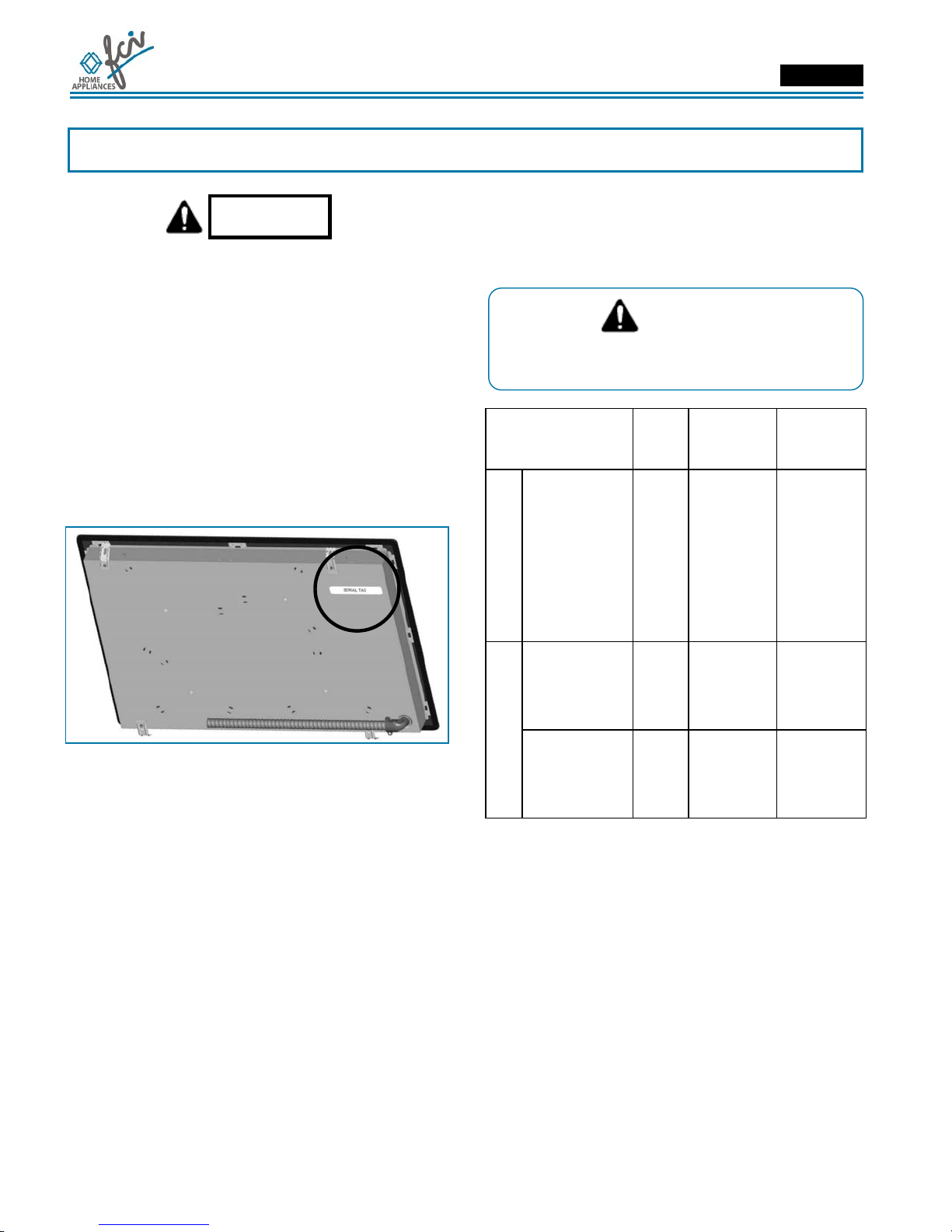
• Write down the model and serial numbers before
installing the cook top. Both numbers are on the
serial rating plate located on bottom of cooktop
box.
Before Starting Installation
WARNING
It is the customer's responsibility to contact a
qualified electrical installer. To assure that the
electrical installation is Adequate and in
conformity with national electrical code:
ANSI/NFPA 70-latest edition** or CSA standards
C22.1-94, Canadian Electrical Code, part No.0-
M91 - latest edition*** and all local codes and
ordinances.
Copies of the standards listed may be obtained from:
** National Fire Protection Association One Batterymarch Park
Quincy, Massachusetts 02269
*** CSA International 8501 East Pleasant Valley Rd. Cleveland,
OH 44131-5575
To eliminate the risk of burns by reaching over
heated surface units, cabinet storage space located
above the surface units should be avoided. If he
cabinet storage is to be provided, the risk can be
reduced by installing a range hood that projects
horizontally a minimum of 5" (12,7 cm) beyond the
bottom of cabinet.
Cooktop Installed over Oven Installation
Only certain specified cooktop and oven models are
approved for cooktop over oven installations.
Cooktops approved for this type of installation will
have an approval label located on the outside of the
burner box. If you do not find this label, contact your
dealer to confirm that cooktop is approved. The label
on the bottom of your cooktop lists the cooktop and
oven combinations that are approved for this type of
installation. Refer to oven manufacturer's Installation
Instructions for approval for built-under use and
proper cut-out dimensions.
INST 022
1-1/2” (4 cm) min

Installation Manual
Models ECCB/TCCB 30” – 36” ENGLISH
5
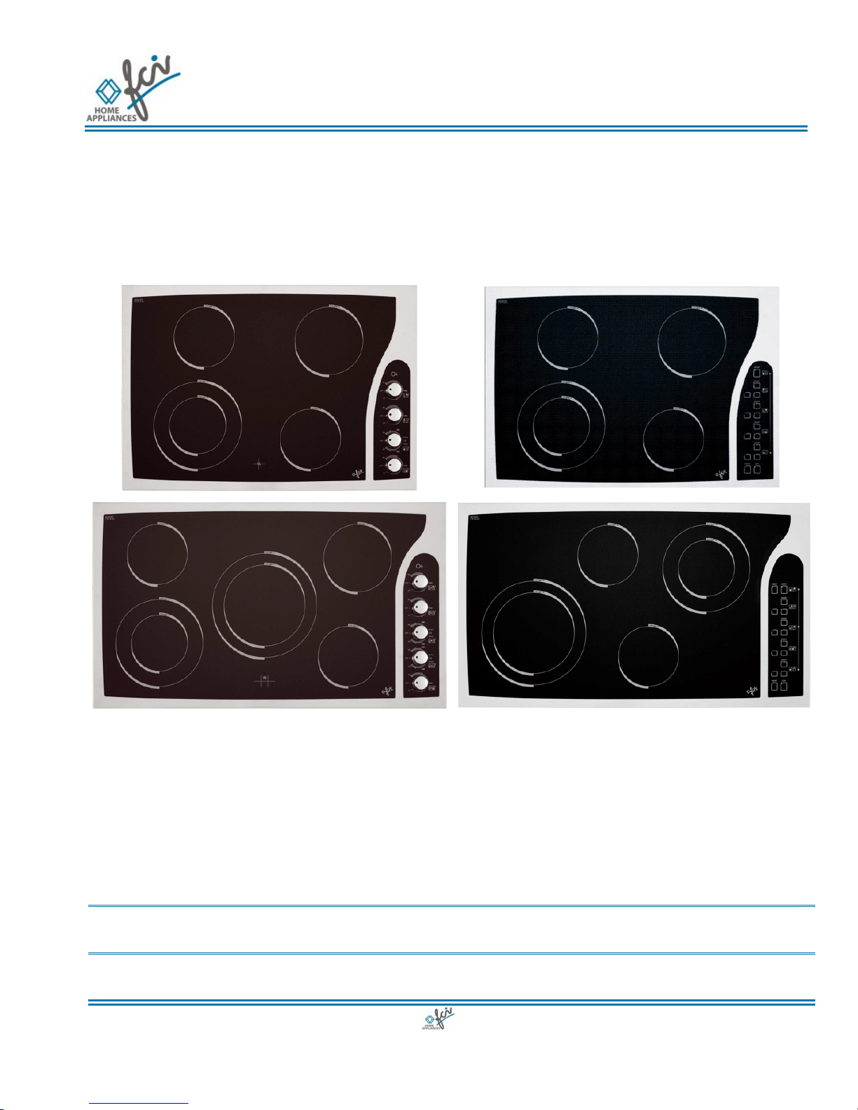
Product Dimensions and Cutout Requirements
Figure 1. Touch control
Figure 2. Energy regulator

Installation Manual
Models ECCB/TCCB 30” – 36” ENGLISH
6
Figure 3. Cutout dimensions and requirements
Installation Manual
Models ECCB/TCCB 30” – 36” ENGLISH
7
CUTOUT
WIDTH A B C D E F G
30”
(76.2cm)
28-1/2”
(72.4 cm)
29”
(73.7 cm)
19-1/4”
(49.0 cm)
19-5/8”
(49.8 cm)
30”
(76.2 cm) min
36”
(91.4 cm)
33-7/8”
(86 cm)
34-9/16”
(87.8 cm)
19-1/4”
(49.0 cm)
19-5/8”
(49.8 cm)
36”
(91.4 cm) min
18” (45.7 cm)
min
Height from
countertop to
nearest
cabinet on
either side of
unit
30” (76.2 cm)
min.
(see note*)
Clearance from
countertop to
unprotected
overhead
surface
2” (5 cm) min
Clearance from
cutout to side
wall on the left
and right of the
unit
13” (33 cm)
Depth of
unprotected
overhead
cabinets
IMPORTANT
Under the cooktop it is necessary to install a partition,
spaced at least 15 mm. from the bottom of the
appliance as shown in figure 3. If an oven or another
appliance is built in under the cooktop, this partition
isn't necessary but in any case keep this clearance
* NOTE
24” (61 cm) min. clearance if bottom of wood or metal cabinets is
protected by not less than 1/4“ (0.6 cm) flame retardant millboard
covered with no less than No. 28 MSG sheet steel 0.015” (0.04 cm)
stainless steel, or 0.024” (0.06 cm) aluminum or 0.020” (0.05cm) copper.
30”(76.2 cm) min. clearance between top of cooking platform and bottom
of unprotected wood or metal cabinet
Important Preparation Suggestions
1. Chamfer all exposed edges of decorative laminate
to prevent damage from chipping.
2. Radius corners of cutout and file to Insure
smooth edges and prevent corner cracking.
Recommend 1/4“or 3/8“diameter drill In each
corner.
3. Rough edges, inside corners which have not been
rounded and forced fits can contribute to cracking
of the countertop laminate.
This cooktop has been designed with wide
tolerances of cut-out to cover possible
replacement with other brands. We recommend to
that you consider the minimum dimension of cut-
out size In the case of new Installation.
Some cut out sizes for possible replacements:
Dim. Inches cm
• 30" 29" x 19-5/8” 73,7 x 49,8
• 36" 34-9/16" x 19-5/8” 87,8 x 49,8

Installation Manual
Models ECCB/TCCB 30” – 36” ENGLISH
8
Cooktop Installation
WARNING
• Excessive Weight Hazard
Use two or more people to move and install
cooktop.
Failure to do so can result in back or other injury.
• Cut Hazard
Beware of sharp edges. Use the polystyrene ends
when carrying the product. Failure to use caution
could result in minor injury or cuts.
• Always consult the countertop manufacturer for
specific instructions.
• Ensure the countertop is square and level and
ensure no structural members interfere with space
requirements.
• Prepare the cut-out according to the instructions
(see cut-out dimensions).
• Make sure the wall coverings, countertop and
cabinets around the cooktop can withstand heat
(up to 200 °F / 93 °C).
Figure 4. Tools you will need

Installation Manual
Models ECCB/TCCB 30” – 36” ENGLISH
9
Step 1
Remove packaging materials and literature package
from the cooktop before beginning installation.
Remove Installation Manual from literature pack and
read them carefully before you begin.
Figure 5. Parts
Step 2
Place a towel or table cloth onto the counter top. Lay
the cooktop upside down onto the protected surface.
Figure 6.
Step 3
A foam tape is provided to seal the cooktop edges to
the countertop.
Apply tape approximately 1/16" (1.5 mm) from the
glass edge to the underside of the cooktop glass. Use
tape around the entire glass perimeter. Cut off excess
where tape ends butt.
Figure 7.

Installation Manual
Models ECCB/TCCB 30” – 36” ENGLISH
10
Step 4
Four clamp brackets are provided to clamp the
cooktop to the countertop. The bracket may be
installed before the cooktop is placed into the cutout.
Install the clamp brackets as shown on the front and
back of the box then rotate brackets so that they do
not extend beyond edge of burner box bottom.
Tighten screws just enough to hold brackets in place
when cooktop is put into cutout.
Figure 8.
Step 5
Insert the cooktop centered into the cutout opening.
Make sure the front edge of the counter top is parallel
to the cooktop. Make final check that all required
clearances are met.
Figure 9.
Step 6
Loosen the screws, rotate the brackets so that they
extend beyond edge of the burner box. Tighten
screws securely.
Figure 10.
Installation Manual
Models ECCB/TCCB 30” – 36” ENGLISH
11
Figure 11.
Figure 12.
WARNING
THE CONDUIT IS 3 FEET LONG
The junction box, must be located where it will
allow considerable slack in the conduit for
serviceability.
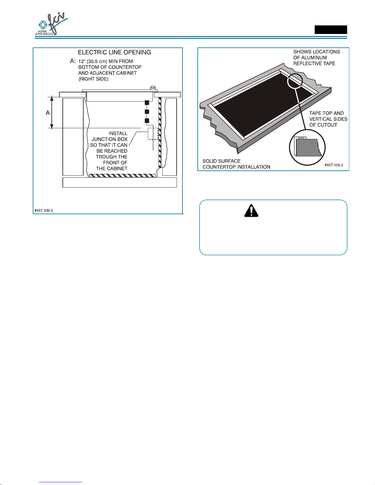
Important:
• For solid surface material installations such as
Surel™ and Corian®, consult with solid surface
manufacturer. Apply heat reflective tape such as
Scotch® Aluminum Foil Tape #425 or #427
around the cutout so that it folds over on the top
and sides.
• Do not wrap the tape underneath the cooktop.
Be sure the tape extends beyond the outermost
flange of the cooktop. All corners should be
covered with tape.
Installation Manual
Models ECCB/TCCB 30” – 36” ENGLISH
12
Electrical Connections
DANGER
Disconnect power before servicing the
product. Failure to do so could result in death
or electrical shock.
General information
This cooktop does not require a neutral connection. If
the cooktop is to be completely enclosed in a cabinet,
feed the cooktop cable through the opening in the
cabinet. Make the electrical connection following the
appropriate steps for your installation.
Your cooktop must be connected to the proper
electrical voltage and frequency as specified in the
table on the right.
Figure 13. Location of serial tag
Connect with copper wire only
If the house has aluminum wiring, follow the
procedure below:
1. Connect the aluminum wiring to the copper wire
by using special connectors designed and
Underwriters Laboratories-listed for joining copper
to aluminum. Follow the electrical connector
manufacturer's recommended procedure.
2. Aluminum/copper connection must conform with
local codes and industry- accepted wiring
practices.
The flexible conduit (supplied) 3 feet long (100 cm)
located at the right rear of the cooktop bottom box
should be connected directly to junction box. Do not
cut the conduit. A U.L - or CSA - listed conduit
connector must be provided at each end of the power
supply cable (at the cooktop and at the junction box.)
A time delay fuse or circuit breaker is recommended.
Do not ground to a gas pipe. Do not have a fuse in the
grounding or neutral circuit.
Fuse both supply (phase) lines.
WARNING
Improper connection of aluminum house wiring to
the copper leads can result in a serious problem.
Model Power Required
power
supply
Minimum
supply wire
size
30”
TCCB 33052/**
TCCB 33053/**
TCCB 33066/**
TCCB 33067/**
ECCB 33050/**
ECCB 33051/**
ECCB 33070/**
ECCB 33071/**
6.7kW 240 V 28 A
60Hz No.
10AWG
TCCB 33656/**
TCCB 33657/**
TCCB 33668/**
TCCB 33669/**
7.6kW 240 V 32 A
60Hz No.
10AWG
36” ECCB 33654/**
ECCB 33655/**
ECCB 33674/**
ECCB 33675/**
9.4kW 240 V 39 A
60Hz No.
10AWG
*Digits identifying color cooktop
National Fire Protection Association
Batter/march Park Quincy, Massachusetts 02269
A three-wire, single phase, 240 volt 60 cycle electrical
system (properly circuit protected to meet Local
Codes of NFPA No.70) must be provided. Unit must
be properly grounded in accordance with local wiring
code. The chart below recommends the minimum
circuit protector and wire size if the appliance is the
only unit on the circuit. If smaller sizes of wire are
used, the unit efficiency will be reduced and a fire
hazard may be created. It is advisable that the
electrical wiring and hookup be accomplished by a
competent electrician.
Installation Manual
Models ECCB/TCCB 30” – 36” ENGLISH
13
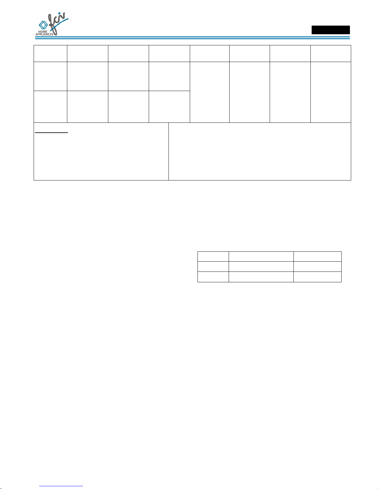
Recommended Minimum
kW Rating on
serial plate
Circuit protection
in amperes Wire size
(AWG)
0-4.8
20 12
4.9-6.9
30 10
7.0-9.9
40 8
10.0-11.9
50 8
12.0-14.9
60 6
Be sure your appliance is properly installed and
grounded by a qualified technician. Ask your
dealer to recommend a qualified technician or an
authorized repair service. This cooktop does not
require a neutral connection. If the cooktop Is to
be completely enclosed In a cabinet, feed the
cooktop cable through the opening in the cabinet.
Make the electrical connection following the
appropriate steps for your installation.
This appliance is manufactured with a green ground
wire connected to the cooktop chassis. After making
sure that the power has been turned off, connect the
flexible conduit from the cooktop to the junction box
using a U.L. listed conduit connector. Figures 14 and
15 and the instructions provided below present the
most common way of connecting the cooktops. Your
local codes and ordinances, of course, take
precedence over these instructions. Complete
electrical connections according to local codes and
ordinances
DANGER
Risk of Electric Shock, frame grounded to
neutral of appliance through a link.
Grounding through the neutral conductor is prohibited
for new branch-circuit installations (1996 NEC);
mobile homes; and recreational vehicles, or in an area
where local codes prohibit grounding through the
neutral conductor.
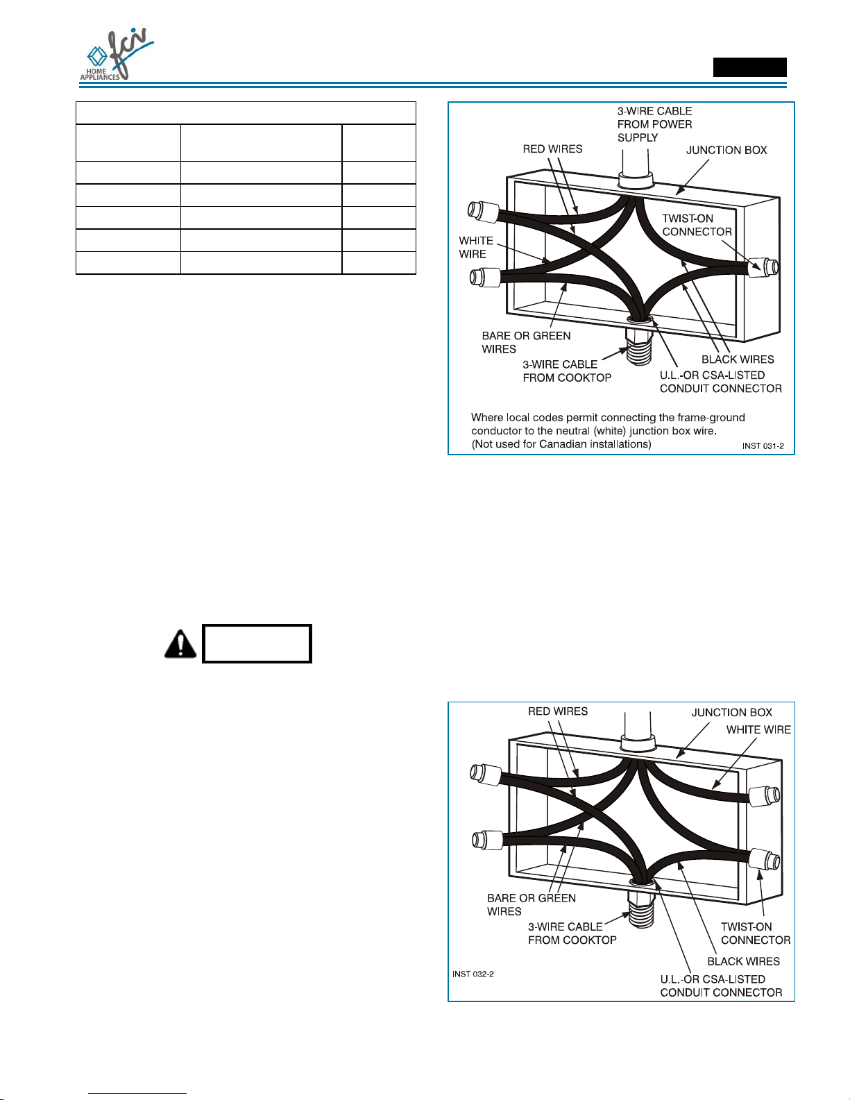
3-Wire branch circuit
Where local codes allow the connection of ground
wire from the cooktop to the branch circuit neutral wire
(gray or white colored wire) proceed as follows (see
figure 14).
1. If local codes permit, connect the green GROUND
wire from the cooktop to the branch circuit neutral
wire (gray or white colored wire).
2. Connect the red and black leads from the cooktop
to the corresponding leads in the junction box.
Figure 14.
4-Wire branch circuit
Refer to figure 15:
1. Connect the green ground wire from the cooktop
to the ground wire in the junction box (bare or
green colored wire).
2. Connect the red and black leads from the cooktop
to the corresponding leads in the junction box.
3. Connect the white wire from the cooktop to the
neutral (gray or white) wire in the junction box.
4. Terminate and insulate the neutral (gray or white
colored wire) in the junction box.
Figure 15.

Installation Manual
Models ECCB/TCCB 30” – 36” ENGLISH
14
Notes
Manuel d’Installation
Modèles ECCB/TCCB 30” – 36” FRANÇAIS
15
Tables des matieres Page
Avertissement Spéciaux................................................. 16
Dimensions du Produit et Découpe............................... 17
Conseils importants de préparation................................... 19
Installation de la Table de Cuisson ............................... 20
Connexions Electriques ................................................. 24
Informations générales...................................................... 24
Connexion à 3 fils.............................................................. 25
Connexion à 4 fils.............................................................. 25
Veuillez prêter attention à ces symboles que vous
rencontrerez dans ce manuel
DANGER
Si vous ne suivez pas IMMEDIATEMENT ces
instructions, vous courez le risque de mourir ou
d’être sérieusement blessé.
AVERTISSEMENT
• Ce symbole signifie que la sécurité est en
danger. Il signale les risques potentiels qui
peuvent entraîner la mort ou des blessures à
l’opérateur ou aux autres.
• Si vous ne suivez pas ces instructions à la
lettre, vous courez le risque de mourir ou
d’être sérieusement blessé.
BIEN LIRE CES INSTRUCTIONS ET LES
CONSERVER.
À l’installateur:
Laissez ces instructions avec l’appareil.
Au client:
Gardez ces instructions comme référence future.
AVERTISSEMENT
• La non-observation des instructions
contenues dans ce manuel peut entraîner la
mort ou des blessures sérieuses du fait d’un
incendie ou d’une explosion.
• Ne pas stocker ou utiliser de l’essence ou
d’autres liquides inflammables à proximité de
cet appareil ou de tout autre appareil
électroménager.

Manuel d’Installation
Modèles ECCB/TCCB 30” – 36” FRANÇAIS
16
AVERTISSEMENT
Avertissement Spéciaux
Veuillez lire les instructions avant toute utilisation
Il est de votre responsabilité d’installer l’appareil
correctement. Confiez l’installation de cette table de
cuisson à un technicien qualifié.
Important:
• Respecter les règlements et ordonnances en
vigueur.
• Avant d’installer la table de cuisson, veuillez
noter les numéros de modèle et de série. Ces
deux numéros se trouvent sur la plaquette
signalétique située en dessous de la caisse de la
table de cuisson.
Avant de Procéder à l’Installation
AVERTISSEMENT
La responsabilité revient au client de contacter un
électricien installateur qualifié. Veuillez vous
assurer que l’installation électrique est adéquate
et conforme à la réglementation électrique
nationale : ANSI/NFPA 70 -dernière édition ** ou
normes CSA C22.1-94, réglementation électrique
canadienne, partie No.0-M91 – dernière édition
*** et tous les règlements et ordonnances locaux.
Copies des normes mentionnées ci-dessus peuvent être obtenues:
** National Fire Protection Association One Batterymarch Park
Quincy, Massachusetts 02269
*** CSA International 8501 East Pleasant Valley Rd. Cleveland,
OH 44131-5575
Pour éviter le risque de brûlures en touchant les
surfaces chauffées, l’espace de stockage du meuble
au dessus des unités de surface doit être évité. Si le
meuble de stockage est fourni, le risque peut être
réduit en installant une hotte qui projète
horizontalement un minimum de 5" (12,7 cm) sous le
dessous du meuble.
Table de cuisson installe au-dessus d’un
four
Uniquement certains fours et tables de cuisson sont
agréés pour être installé l’un au-dessus de l’autre.
Les tables de cuissons agréés pour ce type
d’installation ont une étiquette d’homologation situé
sur l’extérieur de la caisse du brûleur. Si vous ne
trouvez pas cette étiquette, contactez votre
distributeur afin qu’il vous confirme que votre table
est agréée. L’étiquette en-dessous de votre table de
cuisson mentionne les combinaisons possibles de
table de cuisson et four qui sont agréés pour ce type
d’installation. Les fours agréés pour ce type
d’installation auront une étiquette d’homologation
située au-dessus du four. Si vous ne trouvez pas
cette étiquette, contactez le distributeur pour vous
confirmer le four est agréé pour cette installation. Se
reporter aux instructions d’installation du fabricant du
four pour savoir si le four est agréé pour cette
utilisation et obtenir les dimensions correctes de
découpe.

Manuel d’Installation
Modèles ECCB/TCCB 30” – 36” FRANÇAIS
17
Dimensions du Produit et Découpe
Figure 1. Commande sensitive (Touch Control)
Figure 2. Régulateur d’énergie (Energy Regulator)

Manuel d’Installation
Modèles ECCB/TCCB 30” – 36” FRANÇAIS
18
Figure 3. Dimensions pour la découpe
Manuel d’Installation
Modèles ECCB/TCCB 30” – 36” FRANÇAIS
19
DÉCOUPE
LARGEUR A B C D E F G
30”
(76.2cm)
28-1/2”
(72,4 cm)
29”
(73,7 cm)
19-1/4”
(49,0 cm)
19-5/8”
(49,8 cm)
30”
(76,2 cm) min
36”
(91.4 cm)
33-7/8”
(86 cm)
34-9/16”
(87,8 cm)
19-1/4”
(49,0 cm)
19-5/8”
(49,8 cm)
36”
(91,4 cm) min
18” (45,7 cm)
min
Hauteur min.
du plan de
travail au
meuble le plus
près des deux
cotés de
l’appareil
30” (76,2 cm)
min.
(voir note*)
Du plan de
travail à la
surface non
protégée à la
verticale
2” (5 cm) min
Espace min.
de la découpe
à la paroi
latérale sur la
gauche et la
droite de
l’appareil
13” (33 cm)
Profondeur des
meubles non
protégées à la
verticale
IMPORTANT
En dessous de la table de cuisson, il est nécessaire
d’installer une cloison, espacée d’au moins 15 mm du
fond de l’appareil comme indiqué sur la figure 3. Si
un four ou un autre appareil électrodomestique est
intégré sous la table de cuisson, cette cloison n’est
pas nécessaire mais dans tous les cas, conservez la
distance indiquée.
* NOTE
24” (61 cm) espace min. si le bas des meubles en bois ou en métal est
protégée par au moins 1/4“ (0,6 cm) de carton-reliure ignifuge avec une
tôle d’acier inoxydable No. 28 MSG d’au moins 0.015”(0,04 cm), ou
d’aluminium 0.024”(0,06 cm) ou de cuivre 0.020” (0,05cm). 30”(76,2 cm)
d’espace min. entre le haut de la plate-forme de cuisson et le bas du
meuble non-protégé en bois ou métal.
Conseils importants de préparation
1. Biseautez tous les bords exposés du contre-plaqué
décoratif pour empêcher qu’ils ne s’écaillent.
2. Arrondissez les quatre coins de la découpe et
limez le pourtour pour que les bords soient
lisses et que les coins ne se fissurent pas.
Utilisez une mèche de 1/4‘’ ou 3/8’’ pour percer
les trous à chaque angle.
3. Si les bords ne sont pas lisses, l’intérieur des coins
n’est pas arrondi et l’encastrement a été forcé, il
est possible que le contre-plaqué du plan de travail
se fendille.
Cette table de cuissons a été conçue avec de
grande tolérance de découpe pour couvrir le
replacement possible avec d’autres marques.
Quelques découpes pour des remplacements
possibles:
Dim. Inches cm
• 30" 29" x 19-5/8” 73,7 x 49,8
• 36" 34-9/16" x 19-5/8” 87,8 x 49,8

Manuel d’Installation
Modèles ECCB/TCCB 30” – 36” FRANÇAIS
20
Installation de la Table de Cuisson
AVERTISSEMENT
• Risque du fait du poids excessif
Soyez à deux personnes ou plus pour porter et
installer la table de cuisson. Sinon, vous risquez
de vous blesser au dos ou de subir d’autres
blessures.
• Risque de coupure
Méfiez-vous des bords tranchants et des
extrémités du polystyrène lorsque vous portez le
produit. Sinon, vous risquez de vous couper ou de
vous faire légèrement mal.
• Toujours consulter le fabricant du plan de travail
pour les instructions spécifiques.
• Bien vérifier que le plan de travail est carré et à
niveau et assurez-vous qu’aucun élément de
structure n’interfère avec les exigences d’espace.
• Préparez la découpe selon les instructions (voir
dimensions découpe).
• Bien vérifier que les éléments suspendus, le
plan de travail et les meubles autour de la table
de cuisson résistent à la chaleur (jusqu’à 200 °F /
93 °C).
Figure 4. Les outils dont vous aurez besoin
Other manuals for ECCB 30"
1
This manual suits for next models
1
Table of contents
Languages:
Other FCI Home Appliances Cooktop manuals


Popular Cooktop manuals by other brands


Gorenje
Gorenje ECS63EHL Instructions for use, mounting and connection

Toastmaster
Toastmaster TMPHF Installation and operation instruction

Gaggenau
Gaggenau VI424 instruction manual

Thermador
Thermador COOKSMART CIS365GB Product information

KitchenAid
KitchenAid KERA205PBL3 parts list

saro
saro CB-20A user manual