FDS FD600CAM-2 Ver 28V User manual

Document Number:
MAN –FD600CAM-2 (VER 28V)
Rev:
E
Revision Date:
07/11/2017
Page 1 of 11
©2017 FDS Avionics Corp.
All Rights Reserved.
TECHNICAL SUPPORT
470-239-7421 or FDSAvionics.com
Installation and Operation Manual
FD600CAM-2/FD600CAM-2 Ver 28V
Glareshield Camera

Document Number:
MAN –FD600CAM-2 (VER 28V)
Rev:
E
Revision Date:
07/11/2017
Page 2 of 11
©2017 FDS Avionics Corp.
All Rights Reserved.
TECHNICAL SUPPORT
470-239-7421 or FDSAvionics.com
Table of Contents
General Information......................................................................................................3
Front View......................................................................................................................3
Specifications................................................................................................................ 3
Installation Instructions................................................................................................4
Power ............................................................................................................................. 4
Wiring Suggestions.......................................................................................................4
Composite Wiring.......................................................................................................... 5
Power & Ground Wiring................................................................................................6
Power/Video...................................................................................................................7
Technical Drawing......................................................................................................... 8
Technical Support.........................................................................................................9
Instructions for Continued Airworthiness .................................................................. 9
Warranty....................................................................................................................... 10
Log of Revisions ......................................................................................................... 11
Document Number:
MAN –FD600CAM-2 (VER 28V)
Rev:
E
Revision Date:
07/11/2017
Page 3 of 11
©2017 FDS Avionics Corp.
All Rights Reserved.
TECHNICAL SUPPORT
470-239-7421 or FDSAvionics.com
General Information
The FD600CAM-2 and the FD600CAM-2 Ver 28V are Glareshield Cameras. This small
color camera, when mounted in the cockpit, will provide passengers with an opportunity
to observe taxi, take-off, and landing, adding a whole new dimension to the In-Flight
Entertainment experience!
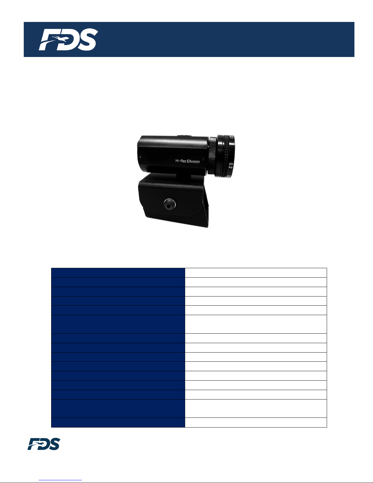
Front View
Specifications
Video System
NTSC or PAL
Video Output
1Vp-p, 75 Ohms
Camera Sensor
1/3” Color CCD
Camera Lens
4.0mm & 8.00mm (included)
Camera Shutter Speed
F 1.2
Picture Element
811H x 508V NTSC
(795H x 596V PAL)
Horizontal Resolution
480 Lines
Scanning System
2:1 Interlace
Signal to Noise Ratio
>48 dB
Minimum Illumination
.05 Lux
Dimensions, Camera
1.35” (W) x 1.35” (H) x 2.92” (D)
Dimensions, Mount
2.0” (W) x 1.75” (H) x 1.75” (D)
Weight
6 oz
Power
FD600CAM-2 - 12VDC @ 90 mA
FD600CAM-2 Ver 28V –28VDC @ 45 mA
Operating Temperature
14F to 140F

Document Number:
MAN –FD600CAM-2 (VER 28V)
Rev:
E
Revision Date:
07/11/2017
Page 4 of 11
©2017 FDS Avionics Corp.
All Rights Reserved.
TECHNICAL SUPPORT
470-239-7421 or FDSAvionics.com
Installation Instructions
All cabin entertainment equipment, such as the FD600CAM-2 and the FD600CAM-2 Ver
28V, should be installed on a non-essential bus and have a dedicated circuit breaker. It is
a requirement that a switch be installed in the cockpit so that the pilot can de-energize
the entertainment system should it become necessary.
Mounting from the cockpit headliner is suggested. Excessive sunlight will make the video
image hard to see. Mounting inside the cockpit and out of direct sunlight will provide a
“visor” to the camera lens.
Remember to set the camera pointing down at an approximately 60° angle, as this will
optimize the picture for takeoff and landings. When looking at the image while on the
ground have the horizon 2/3 of the way up the video screen in the cabin.
Power
The FD600CAM-2 is a 12VDC camera that requires 90mA power and can operate at 9 -
15VDC. The FD600CAM-2 Ver 28V is a 28VDC camera that requires 45mA power and
can operate at 15 - 29VDC.
Wiring Suggestions
All shields should be grounded to the connector at the source, and floating at the display.
Avoid routing video wiring parallel to:
•AC wiring
•Strobe wiring
•DC motor supply cables
•Inverter cabling
•Or any other potential noise source.
Document Number:
MAN –FD600CAM-2 (VER 28V)
Rev:
E
Revision Date:
07/11/2017
Page 5 of 11
©2017 FDS Avionics Corp.
All Rights Reserved.
TECHNICAL SUPPORT
470-239-7421 or FDSAvionics.com
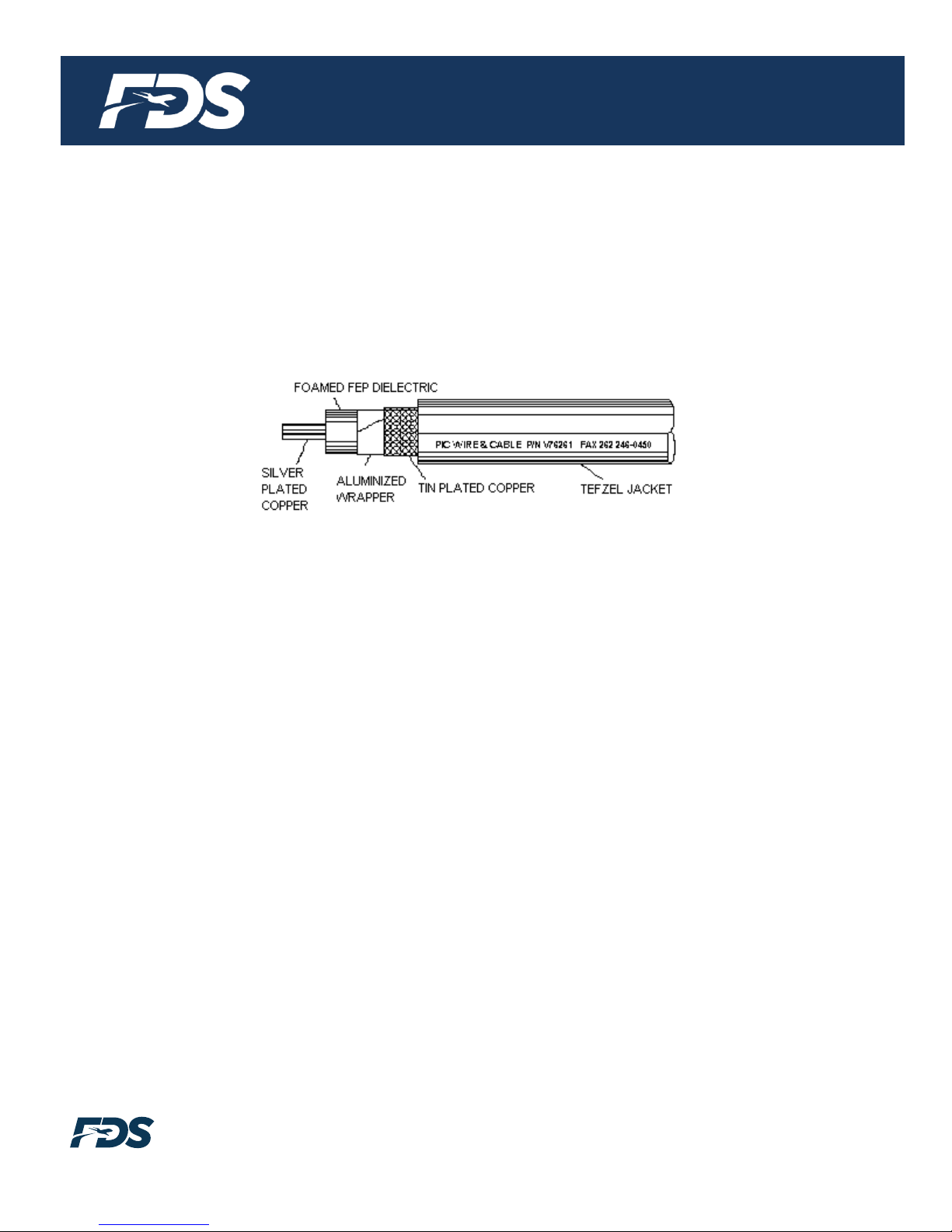
Composite Wiring
Recommended cable for s-video/composite and audio purposes is PIC 75 Ohm Coax,
P/N V76261. This is a lightweight, flexible, and low signal loss cable which meets FAA
flammability requirements of FAR 23.1359(d), FAR 25.853(a) and FAR 25.869(a)(4).
Similar aviation coaxial cable can be used from other vendors, as well. Some aircraft are
prone to AC noise - we recommend adding to the composite source a 75Ohm video
isolation transformer such as Deerfield Laboratory, Inc. Part No. 162-1
(www.deerfieldlab.com, (650) 632-4090). In most cases this should be added to the video
output of the source.

Document Number:
MAN –FD600CAM-2 (VER 28V)
Rev:
E
Revision Date:
07/11/2017
Page 6 of 11
©2017 FDS Avionics Corp.
All Rights Reserved.
TECHNICAL SUPPORT
470-239-7421 or FDSAvionics.com
Power and Ground Wiring
The rated current of the equipment and associated voltage drop should be taken into
consideration when selecting wire gauge. The following example is based on an install
with a 28VDC power system, 1.5-amp equipment load and a total of 50 feet of wire
between the circuit breaker, monitor and ground.
Example: 22awg wire has 16.2 Ohms per 1000 feet, this equates to .81 Ohms for 50
feet. 1.5 Amp of current on .81 Ohms will drop 1.22 Volts.
Resistance of Wire Type M22759/16-**
(** = Gauge)
Gauge (AWG)
OHMS/1000’
24
26.20
22
16.20
20
9.88
16
4.81
12
2.02
10
1.26
8
.701
Also, use short heavy gauge wire and a clean tight connection for ground.
It is the installer's responsibility to understand the product's requirements in order to
install the product in compliance with industry standards and safety.
Document Number:
MAN –FD600CAM-2 (VER 28V)
Rev:
E
Revision Date:
07/11/2017
Page 7 of 11
©2017 FDS Avionics Corp.
All Rights Reserved.
TECHNICAL SUPPORT
470-239-7421 or FDSAvionics.com
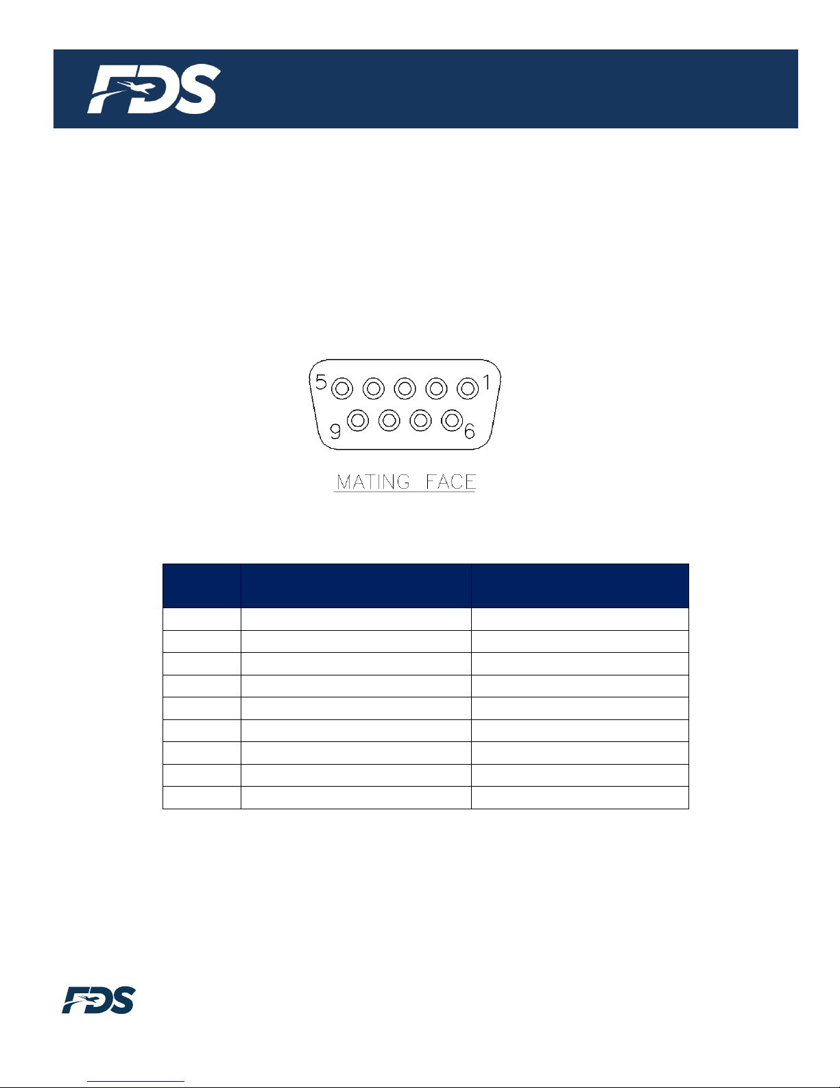
Power/Video
Standard Density DB-9 Receptacle (supplied)
Connector P/N: M24308/2-281 or Equivalent
Crimp Contacts P/N: M39029/63-368 or Equivalent
Pin
Number
FD600CAM-2
Description
FD600CAM-2 Ver 28V
Description
1
12VDC Power
28VDC Power
2
12VDC Ground
28VDC Ground
3
N/C
N/C
4
Composite Video –Shield
Composite Video –Shield
5
Composite Video –Signal
Composite Video –Signal
6
N/C
N/C
7
N/C
N/C
8
N/C
N/C
9
N/C
N/C
Document Number:
MAN –FD600CAM-2 (VER 28V)
Rev:
E
Revision Date:
07/11/2017
Page 8 of 11
©2017 FDS Avionics Corp.
All Rights Reserved.
TECHNICAL SUPPORT
470-239-7421 or FDSAvionics.com
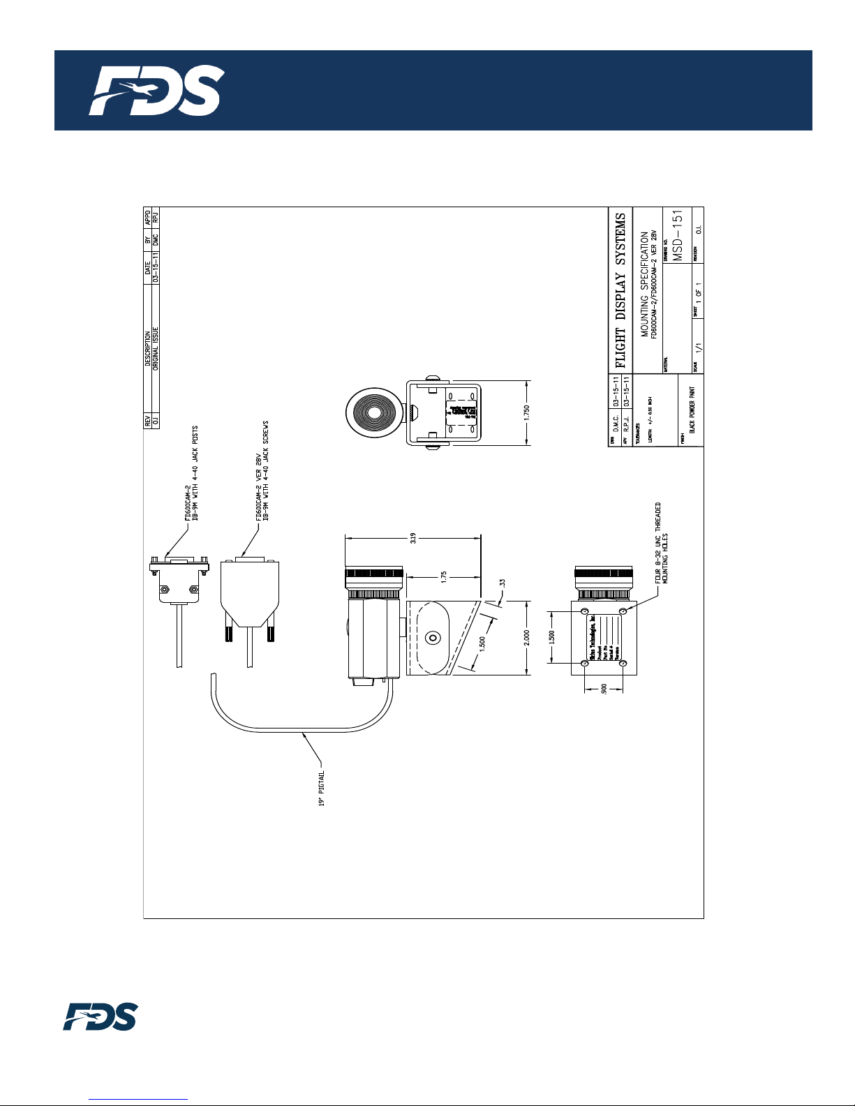
Technical Drawing

Document Number:
MAN –FD600CAM-2 (VER 28V)
Rev:
E
Revision Date:
07/11/2017
Page 9 of 11
©2017 FDS Avionics Corp.
All Rights Reserved.
TECHNICAL SUPPORT
470-239-7421 or FDSAvionics.com
Technical Support
Should you have any questions concerning this product or other FDS Avionics Corp.
products, please contact our Service and Support representatives at 470-239-7421.
FDS Avionics Corp.
6435 Shiloh Road
Alpharetta, GA 30005
Phone: 470-239-7400
Fax: 470-239-7439
Email: [email protected]
For further product information, technical data and sample wiring diagrams, please click
on the Dealers section of our web site at www.FDSAvionics.com
Instructions for Continued Airworthiness
The FD600CAM-2 and the FD600CAM-2 Ver 28V is designed not to require regular
general maintenance.

Document Number:
MAN –FD600CAM-2 (VER 28V)
Rev:
E
Revision Date:
07/11/2017
Page 10 of 11
©2017 FDS Avionics Corp.
All Rights Reserved.
TECHNICAL SUPPORT
470-239-7421 or FDSAvionics.com
Limited Warranty
All FDS Avionics Corp. products are warranted to be free from material or manufacturing defects for a period of 24
months from the date of shipment for General Aviation customers or 12 months from the date of shipment for
Government/Special Mission customers. Any material or repair workmanship for in warranty repair service will be
specifically warranted for 90 days or the remainder of the original warranty period, whichever is longer. If the
original warranty period has expired, the 90-day repair warranty is limited to the material and workmanship
specific to the repair activity completed.
The following conditions are exclusions to warranty coverage:
1. Labor costs associated with installation, removal or reinstallation of any product.
2. Damage to or malfunction caused by any unauthorized alteration made to the product.
3. Resolving signal quality issues caused by externally generated noise introduced by aircraft electrical
systems or other components connected to any FDS product.
4. Any malfunction caused by improper installation or connection to aircraft wiring, industry standard cabin
management/inflight entertainment systems, or third party commercial equipment not specifically identified
as compatible with FDS products.
5. Any malfunction caused by installation that does not conform to precautions associated with operating
environments listed in the operating manual or consistent with industry best practices such as high
temperature, adequate ventilation, high humidity, high dust, or power surges.
6. Cosmetic damage or damage to internal components caused by installation or removal, failure to follow
installation or operating instructions, or any neglect or misuse of the product.
7. Any product that is returned for service with a broken tamper evident seal, indicating tampering or
improper handling of the product by an unauthorized person. Violation of product tamper evident seals or
modification of factory installed serial and PMA labels voids any warranty, either expressed or implied.
The FDS Technical Support team is available to provide distance troubleshooting support during business hours
(8:00am to 5:00pm EST) Monday through Friday at (470) 239-7421.
Many repair requests can be resolved through distance support and may not require return of merchandise to the
factory. If a product must be returned to the factory for repair, an RMA number will be issued as directed by the
Technical Support team and communicated by the Repair Coordinator.
Upon request by the customer, FDS may send a Service Technician onsite to repair any non-PMA products. The
travel expenses incurred to include transportation, lodging and meals along with the technician’s hourly rate shall
be payable by the customer in accordance with FDS’ applicable rates and procedures.
FDS Avionics Corp. will, upon receipt of returned merchandise, remanufacture or replace the unit at our discretion
and return the product by Ground Return Shipping. Express return shipment will be the responsibility of the
sender.
This warranty is not transferable.
Any implied warranties expire at the express limited warranty expiration date. FDS shall not be held liable for any
indirect, special, punitive, incidental or consequential damages.
Some states do not allow limitation on the length of an implied warranty. In such states, the exclusions or
limitations of this limited warranty may not apply.

Document Number:
MAN –FD600CAM-2 (VER 28V)
Rev:
E
Revision Date:
07/11/2017
Page 11 of 11
©2017 FDS Avionics Corp.
All Rights Reserved.
TECHNICAL SUPPORT
470-239-7421 or FDSAvionics.com
Log of Revisions
Rev
Date
Page
Description
A
03/08/2007
Initial Release
B
09/05/08
1
Updated camera lens specs, added operating temperature to
spec list
C
04/14/2009
1,6
Updated specifications, warranty info
D
03/16/2011
Added FD600CAM-2 Ver 28V, new Composite Wiring info, new
Pinout info, new Technical Drawing
E
07/11/2017
All
New Format, New Company Name, Warranty
Table of contents


