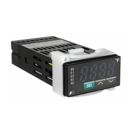
FE SC-E03PK User manual

図3 Fig. 3
図1 Fig. 1
30° 30° 30°30°
危険
SC-E03PK *1, SC-E05PK *1
SC-E1PK *1, SC-E2SPK *1, SC-E3PK *1
上記形式の * 部には次の記号およびそれらを組み合わせた記号の付属形式が付く場合があります。仕様などの詳細はカタログを参照してください。*1 : H
Suffixes listed below may be attached to the above types at portions marked with * . For details regarding specifications, see the catalogue. *1 : H
安全上のご注意
取付け、運転、保守、点検の前に、必ずこの取扱説明書をすべて熟読し、正しくお使いください。この取扱説明書では、安全注意事項のランクを「危険」「注意」として区分
しております。
:取り扱いを誤った場合に、危険な状況が起こりえて、死亡または重傷を受ける可能性が想定される場合。
:取り扱いを誤った場合に、危険な状況が起こりえて、中程度の傷害や軽傷を受ける可能性が想定される場合および物的損害だけの発生が想定される場合。
なお、 に記載した事項でも状況によっては重大な結果に結びつく可能性があります。いずれも重要な内容を記載しておりますので必ず守ってください。
● 通電中は製品に触れたり近づいたりしないでください。感電、火傷のおそれがあります。
●保守・点検は電源を切って行ってください。感電のおそれがあります。
● 取付けは、取扱説明書に規定されたスペース以上を確保して行ってください。火傷、火災のおそれがあります。
● 配線は印加電圧、通電電流に適した電線サイズを使用し、取扱説明書に規定された締付トルクで締付けてください。火災のおそれがあります。
● 電源を切った直後の製品には触らないでください。熱くなっていますので火傷のおそれがあります。
● 電磁接触器本体よりヘッドオン部及び抵抗線を取外して使用しないでください。火災のおそれがあります。
● 配線後に抵抗線の相順が正しいことを内部回路図(図 7)で確認してください。短絡事故発生のおそれがあります。
●製品を廃棄する場合は、産業廃棄物として扱ってください。
Safety Precautions
To ensure proper use of the product, be sure to read this manual and the other attached documents carefully before starting installation, operation, maintenance and
inspection. Within this instruction manual, safety precautions are ranked, in order of importance, as either “Warning” or “Caution”.
An operator may be killed or seriously injured by a hazardous condition resulting from improper operation.
An operator may suffer minor injuries and/or objects may be damaged by a hazardous condition resulting from improper operation.
Under certain conditions, improper operation may result in serious injury and/or damage even if it is labeled only as“Caution”. Every item indicated by either
“Warning” or “Caution” should be considered significant. Be sure to give particular care to those items.
● For wiring, select wire sizes suitable for the applied voltage and current.
● Tighten wires with the tightening torque specified in the instruction manual. Failure to do so may result in fire.
● Do not touch the product immediately after the power is turned off. As it may still be hot, burns may result.
● Remove neither head-on unit nor the resistance wire from the main body of a magnetic contactor. Failure to do so may result in fire.
● For wiring, make sure that the phase sequence of the resistance wire is correct according to the internal circuit diagram. (Fig.7)
Failure to do so may result in short-circuit.
● Treat the product as industrial waste when discarding.
1. 荷ほどき Unpacking
(1) 形式、制御コイル電圧および適用容量がご要求の仕様と一致しているか確認してください。
(2) 輸送中の事故などによる部品の脱落や破損がないか点検してください。
(1) Check that the type, coil voltage, and applicable capacity match the requested specifications.
(2) Make sure that no parts have been lost or damaged.
2. 保管 Storage
高温多湿、腐食性ガスおよび直射日光を受ける場所を避け、梱包状態で保管してください。
Store the unit in the packing box. Do not store the packing box in a location subject to high
temperature, high humidity, corrosive gas, or direct sun light.
3. 取付け Mounting
(1) 湿気、じんあい、振動の少ない所に設置してください。
(2) 垂直面に取付けてください。許容傾斜角度は 30°以内です。(図 1)
(3) レール取付けは IEC60715 の 35mm 幅支持レールに取付けできます。レールのパネル取付け方法(図 2)、取付・取外し(図 3)
(4) 取付穴が4ヵ所ある場合は、対角線2ヵ所で取付けてください。(図 4)
(5) 必ず本体フレームを持ち上げて取付けてください。電磁接触器に配線されている抵抗線を持ち上げての取付けを行うと断線,破損のおそれがあります。
(1) Mount in a dry, clean and stable location.
(2) Mounting on a vertical surface. The product must not incline more than 30°. (Fig. 1)
(3) The rail mounting type can be attached on a standard 35mm IEC60715 mounting rail. Fuji type TH35-15AL mounting rail is recommended. Mounting of the rail on the
panel (Fig. 2) Attachment and removal (Fig. 3)
(4) Even if the product is provided with four mounting holes, use any two mounting holes on a diagonal line. (Fig. 4)
(5) Be sure to life the body of the magnetic contactor and mount it. Do not mount the magnetic contactor with the connected resistance wire lifted.
Doing so may result in breaking of wires or damage to the product.
4. 取付けスペース(図 5、6) Mounting space(Fig. 5, Fig. 6)
(1) 取付けは右表の寸法以上離してください。
(2) 密着取付けする場合、使用条件(連続通電使用や高開閉頻度の製品同士を密着取付)によっては、温度上昇によりコイル寿命が
低下することがあります。この様な条件で使用される場合は、製品相互間を 5mm 以上離して使用することをお薦めします。
(1) Mount the products at a distance of at least that shown in the table right.
(2) When units must be installed very closely, the temperature may rise in some conditions (i.e. the power is continuously supplied
for a long time or units that frequently do switching are installed very closely), and it may shorten the life of the coil. Thus, when
installing units very closely, it is recommended to install the units 5 mm or more apart.
●Do not touch the product or approach it when power connected. Electric shock or burns may result.
●Turn off the power before starting maintenance or inspection. Failure to turn off power may result in electric shock or burns.
取
扱説
明
書
INA-F0205a-JE
WARNING
WARNING
この取扱説明書は、最終使用保守責任者のお手
元に届くよう十分にご配慮ください。
This manual should be given to the
person who actually uses the products
and is res
p
onsible for their maintenance.
コン
デ
ンサ開閉用電
磁接触
器 Contactor for Capacitor Switching
形式 Type
INSTRUCTION MANUAL
CAUTION
接地金属 Ground plate
A B
B
接地金属 Ground plate
図6 Fig. 6
注意
A寸法
Dimension A 0mm
B寸法
Dimension B 10mm
C寸法
Dimension C 2mm
注意
注意
危険
CAUTION
図5 Fig. 5
接地金属または
絶縁物
Ground plate or
insulating plate
C
図2 Fig. 2
取付ピッチ
Mounting
pitch
300mm 以下(TH35-15AL)
300mm or less (TH35-15AL)
取付ねじ M5
M5 screw
図4 Fig. 4

図9 Fig. 9
端子板
Terminal plate
圧着端子
Round clamp terminal
抵抗線
Resistance wire
接続電線
Connected wire
5. 配線 Connection
(1)主回路(圧着端子接続) Main terminals (Connection with clamp terminal)
形式 Types SC- E03PK,E05PK E1PK,E2SPK E3PK
接続可能電線サイズ
Connectable wire size [mm2] 0.75~6(8) 0.75~16(22) 1~25(38)
圧着端子の最大幅【注 1】
Max. width of cable lug【Note 1】 [mm] 9.7 12.4 16.8
端子ねじサイズ
Terminal screw size M 4 M 5 M 6
締付け工具【注 2】
Tool【Note 2】 ⊕2 ⊕2 〇 ⊕3
締付けトルク
Tightening torque [N・m] 1.2~1.5 2~2.5 4~5
(2)制御回路 Control terminals
形式 Types 全形式共通 All Types
単線 Solid
より線 Stranded
可とうより線(スリーブ付)【注 3】
Flexible stranded with end sleeve【Note 3】
[mm2]
1×(0.75~2.5)
2×(0.75~1.5)
2×(1.5~2.5)
電線皮むき寸法
Stripped length [mm] 10
圧着端子の最大幅【注 1】
Max. width of cable lug【Note 1】 [mm] 7.7
端子ねじサイズ Terminal screw size M 3.5
締付け工具【注 2】 Tool【Note 2】 ⊕2 ⊖
締付けトルク
Tightening torque [N・m] 0.8~1
6. 動作表示 Operation indicator of contactor
動作表示の位置で動作状態の確認ができます。(図 10)なお、動作表示での操作は感電、火傷のおそれがありますので行わないでください。
Operation indicator shows contactor operates or not. (Fig. 10) Don’t touch or push the operation indicator, or it may result in electric shock or burns.
7. 保守・点検 Maintenance and Inspection
(1) 制御回路電圧は、制御コイル電圧の許容電圧変動範囲内にあることを確認してください。
(2) ねじの緩みがないことを確認してください。
(3) 端子の締付ねじは定期的に締め直してください。
(4) AC 操作の場合、操作電源がひずみ、陥没などのない 50Hz および 60Hz の正弦波であることを確認してください。
(5) 接点交換はできません。
(1) Check that the operating circuit voltage is within the allowable voltage fluctuation range of the coil voltage.
(2) Check that all screws are tightened.
(3) Check that all terminals are tightened with the proper torque periodically.
(4) In AC operation, check that operation power supply is sinusoidal waveform (50Hz and 60Hz) without
distortion or cave-in etc.
(5) Contact cannot be exchanged.
8. 内部回路図 Internal circuit diagram
動作表示
Operation indicator
OFF ON
図10 Fig. 10
最大幅
Max. width
図8 Fig. 8
図12 Fig. 12
【注1】丸形圧着端子最大幅は図 8 をご参照ください。
【注2】 ⊕2:フィリップス H 形 2 番
⊕3:フィリップス H 形 3 番
⊖:I 形ねじ回し I-1×5.5×L タイプB
〇:ソケットレンチ (6.3mm 角ドライブ)
【注3】 より線:より線の数 7 本以下 可とうより線:左記より多芯数な電線
【注4】 圧着端子は図 9 のように接続してください。
【注5】 配線を行わない端子ねじは、すべて締付けてご使用ください。
【注6】 配線後に接続電線を整線等で曲げた場合は、締付トルクが適切である
ことを再度確認してください。
【注7】 配線時の端子カバーの取外し・取付けは図 11 をご参照ください。
【注8】 配線後に抵抗線の相順が正しい位置に接続されていることを、図 7 の
回路図よりご確認ください。
【Note 1】 Use cable lug whose width is the size specified at the maximum width
or terminal less. (Fig. 8)
【Note 2】 ⊕2:Philips PH2 φ6
⊕3:Philips PH3 φ8
⊖:Slotted-head screw I-1×5.5×L Type B
〇:Socket wrench (6.3 square drive)
【Note 3】 Stranded wire : Number of solids ≦ 7
Flexible stranded wire: Number of solids > 7
【Note 4】 Please connect the cable lug as shown in Fig. 9.
【Note 5】 Tighten all terminal screws even if not used.
【Note 6】 After alignment or bending back of connected leads, check the tightening
torque of the clamping screws.
【Note 7】 See Fig. 11 for removal and installation of terminal cover when wiring.
【Note 8】 After wiring, make sure that each resistance wire is connected to a
correct phase according to Fig. 7
A1 A2
93
94
91
92
1/L1 3/L2 5/L3
2/T1 4/T2 6/T3
1/L1 3/L2 5/L3
2/T1 4/T2 6/T3
Aux. 1NO Aux. 1NC
図7 Fig. 7
A1 A2
追加補助接点ユニットは、SZ-AS1(サイドオン)を両側へ2個取付けてのご使用はできません。
左右どちらかで片側1個のみ使用可能です。(図 12)
Two pieces of the auxiliary contact blocks for side mounting “SZ-AS1” must not be use
on both sides of the contactor simultaneously. Either one block on the right side or on the
left side can be mounted.(Fig. 12)
〒103-0011 東京都中央区日本橋大伝馬町 5 番 7 号
(三井住友銀行人形町ビル)
TEL : (03) 5847-8060 FAX : (03) 5847-8182
URL : http://www.fujielectric.co.jp/fcs/
Mitsui Sumitomo Bank Ningyo-cho Bldg.,5-7 Nihonbashi Odemma-cho,Chuo-ku,
Tokyo 103-0011, Japan
Phone : +81-3-5847-8060 Fax :+81-3-5847-8182
URL http://www.fujielectric.co.jp/fcs/
図11 Fig. 11
取外し
Removal
取付け
In
sta
ll
at
i
o
n
①主回路 Main circuit
②補助回路 Auxiliary circuit
③コイル端子 Coil terminal
①-1 ①-2
②
①
②
③
F05166893a
This manual suits for next models
4
Other FE Thermostat manuals
Popular Thermostat manuals by other brands
Energate
Energate Pioneer Z100 Smart Thermostat OPERATING AND INSTALLATION Manual
wattio
wattio THERMIC manual
Daikin
Daikin TSTATD1100-2 Owner's manual and installation instructions
Brivis
Brivis TH4110 quick start guide
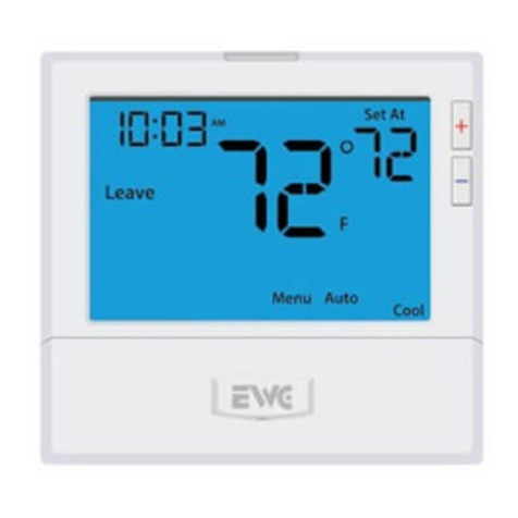
EWC Controls
EWC Controls EWT-855i installation manual

ICE AIR
ICE AIR ELA-8842 user guide
