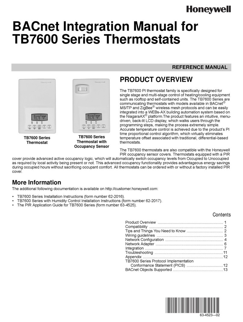
FE PXR3 User manual

Digital Thermostat PXR3
(Replacement for PAS3)
Type: PXR3
Operation Manual
PV
SET1
SET2
AL1
AL2
SEL
°C
INP-TN5A2886-E

2
1 Display and Keys..................................................................................................................... 4
2 Operation................................................................................................................................. 5
2-1 Parameter List................................................................................................................. 5
2-2 Basic Operation............................................................................................................... 7
2-3 Parameter Functions and Method of Settings................................................................. 9
Level 1 parameters (operation mode)............................................................................. 9
PV display ................................................................................................................... 9
Alarm 1 setpoint (SET1) display ................................................................................. 9
Alarm 2 setpoint (SET2) display ................................................................................. 9
Level 2 parameters ........................................................................................................10
Alarm 1 setpoint (SET1) setup...................................................................................10
Alarm 2 setpoint (SET2) setup...................................................................................10
Level 3 parameters ........................................................................................................11
Input type ...................................................................................................................11
Range lower limit setup..............................................................................................12
Range upper limit setup .............................................................................................12
Alarm type 1...............................................................................................................13
Alarm type 2...............................................................................................................13
Alarm 1 hysteresis .....................................................................................................14
Alarm 2 hysteresis .....................................................................................................14
Alarm 1 ON delay time...............................................................................................15
Alarm 2 ON delay time...............................................................................................15
Burn-out direction.......................................................................................................16
Power ON delay time .................................................................................................17
Setup lock ..................................................................................................................18
Level 4 parameters ........................................................................................................19
,QSXW¿OWHUWLPHFRQVWDQW.............................................................................................19
PV offset.....................................................................................................................20
User ZERO adjustment..............................................................................................21
User SPAN adjustment ..............................................................................................21
3 Alarm......................................................................................................................................22
Alarm type ......................................................................................................................22
Alarm setpoint ................................................................................................................22
Energization and de-energization ..................................................................................23
Alarm with hold...............................................................................................................23
Alarm latch by hysteresis ...............................................................................................24
Combining the alarm latch by hysteresis and the alarm with hold .................................24
Alarm ON delay time ......................................................................................................25
Power ON delay time .....................................................................................................25
Combining the power ON delay time and the alarm ON delay time...............................25
4 Troubleshooting........................................................................................................................26
Table of Contents

3
Table 1: Model Codes
Sensor Range Alarms Model
Thermocouple See Table 2 1 PXR3TAY2-0Y061
2 PXR3TAY2-1Y061
Thermistor 0–100°C 1 PXR3HAY2-0Y061
PXR3HAY2-1Y061
Notes
1. You cannot switch between thermocouple input and thermistor input.
2. Default settings are as follows:
Thermocouple version: type K thermocouple, 0–1200°C range
Thermistor version: thermistor input, 0–100°C range
*If you ordered a thermocouple version, you can change the input setting to the one for other thermocouples as shown in
Table 1. If you change the input setting, do not forget to change the range setting as well.
3. For thermistor input version, use the dedicated thermistor that comes with the product.
Table 2: Input Range Codes
Sensor Pn2 code Range (°C)
PSL PSU
Thermocouple
J 2 0 800
K 3 0 1200
R 4 0 1600
T 6 0 400
E 7 0 600
Thermistor PB-36 8 0 100

4
PV
SET1
SET2
AL1
AL2
SEL
°C
⑧ key
⑥Unit indicator
⑨ key
⑩ key
⑦Display
Alarm 2 set value (SET2) indicator ③
Alarm 1 set value (SET1) indicator ②
Process value (PV) indicator ①
Alarm 1 (AL1) indicator ④
Alarm 2 (AL2) indicator ⑤
Display/Indication
No. Name Function
①Process value (PV)
indicator
Lights in green when PV is displayed.
②Alarm 1 set value
(SET1) indicator
Lights in green when the alarm 1 set value is displayed.
③Alarm 2 set value
(SET2) indicator
Lights in green when the alarm 2 set value is displayed.
④Alarm 1 (AL1) indicator /LJKWVLQJUHHQZKHQWKHDODUPRFFXUV
%OLQNVGXULQJRQGHOD\
⑤Alarm 2 (AL2) indicator /LJKWVLQJUHHQZKHQWKHDODUPRFFXUV
%OLQNVGXULQJRQGHOD\
⑥Unit indicator Shows the temperature unit.
⑦7-seg 4 digit LED
39
6(7
6(7
3DUDPHWHUQDPH
3DUDPHWHUVHWYDOXH
,QRSHUDWLRQPRGHOHYHOGLVSOD\V396(7RU6(7
,QSDUDPHWHUVHWWLQJPRGHVOHYHORUGLVSOD\VDSDUDPHWHUQDPHRUD
parameter value
8SRQHUURUVKRZVDQHUURUFRGH
*PV and alarm set values can be set in increments of 1°C.
Setting keys
No. Name Function
⑧Select key Used for switching of display between process value and alarm set value, level
move, switching to parameter setting mode and for data registration.
⑨Up key 8VHGIRUSDUDPHWHUVKLIWLQJUHWXUQLQJRUGDWDFKDQJLQJLQFUHDVLQJ
7KHQXPHULFDOYDOXHLVLQFUHDVHGE\SUHVVLQJWKHNH\RQFH7KHQXPHULFDO
value keeps on increasing by pressing the key continuously.
⑩Down key 8VHGIRUSDUDPHWHUVKLIWLQJWRQH[WRUGDWDFKDQJLQJGHFUHDVLQJ
7KHQXPHULFDOYDOXHLVGHFUHDVHGE\SUHVVLQJWKHNH\RQFH7KHQXPHULFDO
value keeps on decreasing by pressing the key continuously.
1Display and Keys

5
2-1 Parameter List
3DUDPHWHUVDUHFODVVL¿HGLQWRWKHIROORZLQJIRXUOHYHOV
Level Description Notes
Level 1 Process value and alarm setpoint
(indication only)
You cannot change the alarm
setpoint in Level 1.
Level 2 Alarm setpoint change
Level 3 Set up
Level 4 Input compensation
0% *1, *2, *3
100% *1, *2
Alarm 1 setpoint setup Allows you to change the alarm 1
trigger value within the input range.
Name Function Default setting
0%-100% FS
0%-100% FS
10
10
Range Page
ST1
ST2 Alarm 2 setpoint setup Allows you to change the alarm 2
trigger value within the input range.
Your
setting
– *1
Process value
Name Function Default setting
–
––
Range Page
PV
SET1
SET2
Alarm 1 setpoint display
– *1, *3
9
9
9–
Alarm 2 setpoint display
Shows the process value
Shows the alarm 1 setpoint
Shows the alarm 2 setpoint
Your
setting
*7, *9
*7, *8
0°C *7
2 *3
1 *1, *2
1 *1, *2, *3
0 *4
0 *3, *4
H
0
14
14
15
15
16
17
018
Name Function Default setting
2–8
(excluding 5)
-1999 to 9999
-1999 to 9999
0-8 1
0-8
12
12
13
13
0-120 s
0-120 s
H/L
0-120 s
0-2
Range Page
Input type
Range lower limit setup
Allows you to change the type of input. 11
Allows you to set the lower limit of the input
range.
Allows you to set the upper limit of the input
range.
Burn-out direction
Allows you to set the input value when an input
error is detected, to either high limit or low limit.
Power ON delay time Allows you to set the delay time during which
no output is emitted after power ON.
Alarm type 1
Allows you to select the type of alarm.
Alarm type 2
Setup lock
Allows you to select if parameter change is
allowed or not.
LoC = 0: All parameters can be changed.
LoC = 1: No change is permitted.
LoC = 2: ST1 and ST2 can be changed.
Range upper limit setup
Alarm 1 hysteresis Allows you to set the on/off hysteresis width
of alarm output.
Alarm 2 hysteresis
Alarm 1 ON delay time Allows you to set the delay time until the
alarm starts.
Alarm 2 ON delay time
Pn2
PSL
brn
oPd
PA1
PA2
LoC
PSU
HY1
HY2
Pd1
Pd2
Your
setting
0%-110% FS
0%-110% FS
Level 2 Parameters
Level 3 Parameters
2Operation
Level 1 Parameters

6
5.0
0°C *1, *2
0°C *1, *2
0°C *1, *2
19
20
21
21
Name Function Default setting
0.0-90.0 s
-10% to 10% FS
-50% to 50% FS
-50% to 50% FS
Range Page
User SPAN adjustment Allows you to adjust the span point.
Input filter time
constant
Allows you to set the time constant.
*Setting is available in 0.5 seconds
increments. Setting to “0.0” turns off the filter.
PV offset Allows you to shift the process value (PV)
on display.
AJS
PdF
POF
AJO User ZERO adjustment Allows you to adjust the zero point.
Your
setting
50
100
Notes:
1. Parameters marked with change when PSL and/or PSU is changed.
*PSU = range upper limit, PSL = range lower limit
2. FS (full scale) means the value of PSU - PSL.
For example, when PSL = 0, and PSU = 1200,
50% FS = (1200-0) × = 600
3. Parameters indicated with do not appear on the versions that have only one alarm.
4. The accuracy of the alarm delay time and the power ON delay time is less than 1 second.
5. A difference of 1°C may arise between the indication and the alarm output depending on the range setup.
(Example: If the alarm set value is 200°C, an alarm occurs when the indication is 200°C in some cases, but in other cases,
an alarm occurs when the indication is 201°C.)
6. There may be the cases where over-range (UUUU) or under-range (LLLL) code does not appear, if a large value is set for PV offset,
user zero adjustment or user span adjustment.
7. Parameters indicated with are not displayed on the thermistor input version.
8. Default setting of input type: thermocouple: 3, thermistor: 8
9. Default setting of the range upper limit: thermocouple: 1200, thermistor: 100
Level 4 Parameters

7
2-2 Basic Operation
When you turn on the digital thermostat, the screen shows “– – – –“ and then the process value.
7KHEHORZ¿JXUHVKRZVDQH[DPSOHZKHQWKHSURFHVVYDOXHLV&DQGWKHDODUPLVDFWLYH
PV
SET1
SET2
AL1
AL2
SEL
°C
Display mode switching
Press for about
3 seconds.
SEL
SEL
Press for about
7 seconds.
SEL
Operation mode (level 1)
Level 2 parameter block
Press for about
9 seconds.
SEL
Level 3 parameter block Level 4 parameter block
Process value (PV) display
SEL
Press
once
Alarm 1 set value (SET1) display Alarm 2 set value (SET2) display
SEL
Press
once
SEL
Press
once
Press for about 3
seconds to go back
to the process value
(PV) indication.
SEL
Press for about 3
seconds to go back
to the process value
(PV) indication.
SEL
Press for about 3
seconds to go back
to the process value
(PV) indication.
Notes Ɣ7RPRYHDPRQJWKHGLVSOD\VXVH6(/NH\7KHGXUDWLRQWRSUHVVWKH6(/NH\GHILQHVWKHGHVWLQDWLRQGLVSOD\
Ɣ7RFKDQJHWKHDODUPVHWSRLQWDFFHVVWKHSDUDPHWHUV67RU67LQWKHOHYHOSDUDPHWHUEORFN
Ɣ7KHGLVSOD\FKDQJHVEDFNWRSURFHVVYDOXHGLVSOD\RIWKHRSHUDWLRQPRGHZKHQVHFRQGVKDYHSDVVHGDIWHUWKHODVWNH\RSHUDWLRQ
PV
SET1
SET2
AL1
AL2
SEL
°C
PV
SET1
SET2
AL1
AL2
SEL
°C
PV
SET1
SET2
AL1
AL2
SEL
°C
PV
SET1
SET2
AL1
AL2
SEL
°C
PV
SET1
SET2
AL1
AL2
SEL
°C
PV
SET1
SET2
AL1
AL2
SEL
°C
PV
SET1
SET2
AL1
AL2
SEL
°C
PV
SET1
SET2
AL1
AL2
SEL
°C
PV
SET1
SET2
AL1
AL2
SEL
°C
PV
SET1
SET2
AL1
AL2
SEL
°C
PV
SET1
SET2
AL1
AL2
SEL
°C

8
Parameter setting
1) Select a parameter you want to set
by pressing the or key.
2) Press the key to display the
parameter set value.
3) Press the or key, to change
the parameter set value.
4) To save the change, press the
key or just wait for 3 seconds.
The value will stop blinking, and
the display changes back to the
parameter name display.
<Parameter setting procedure>
Parameter name display
1)
2)
3)
3)
4)
Set value display
The increase/decrease speed
changes when the or key
is kept pressed.
1) To move to the operation mode
display, press the key for 3
seconds in the parameter name
display.
<Method for move of level 1>
SEL
SEL
Blink
Blink
SEL
SEL
SEL
PV
SET1
SET2
AL1
AL2
SEL
°C
PV
SET1
SET2
AL1
AL2
SEL
°C
PV
SET1
SET2
AL1
AL2
SEL
°C
PV
SET1
SET2
AL1
AL2
SEL
°C

9
2-3 Parameter Functions and Method of Settings
Level 1 parameters (operation mode)
PV
SET1
SET2
AL1
AL2
SEL
°C
PV
SET1
SET2
AL1
AL2
SEL
°C
PV
SET1
SET2
AL1
AL2
SEL
°C
PV display
Alarm 1 setpoint (SET1) display
Alarm 2 setpoint (SET2) display
—————————————————————————————————————————————
/HYHOSDUDPHWHUVDVVRFLDWHZLWKWKHGLVSOD\GXULQJLQLWLDOVWDUWXSDQGGLVSOD\GXULQJRSHUDWLRQ
<RXFDQQRWFKDQJHSDUDPHWHUVLQWKHOHYHOSDUDPHWHUV
/HYHOSDUDPHWHUVLQFOXGH39GLVSOD\DODUPVHWSRLQW6(7DQGDODUPVHWSRLQW6(7
,QGLFDWRUODPSV396(7DQG6(7WHOO\RXZKLFKYDOXHLVEHLQJGLVSOD\HG
Related parameters: (page 10), (page 10)
[Examples] ———————————————————————————————————————
PV display
PV
SET1
SET2
AL1
AL2
SEL
°C
When the process value is 25°C
Alarm 1 setpoint (SET1) display
PV
SET1
SET2
AL1
AL2
SEL
°C
When the alarm 1 setpoint is 1200°C
Alarm 2 setpoint (SET2) display
PV
SET1
SET2
AL1
AL2
SEL
°C
When the alarm 2 setpoint is 0°C

10
Level 2 parameters
Alarm 1 setpoint (SET1) setup
Alarm 2 setpoint (SET2) setup
—————————————————————————————————————————————
$OORZV\RXWRFKDQJHWKHVHWSRLQWIRUWKHDODUPDQGWKHDODUP
<RXFDQVHWWKHDODUPVHWSRLQWLQWKHUDQJHEHWZHHQ (range lower limit) and (range upper limit).
Related parameters: (page 12), (page 12), (page 13), (page 13)
[Setting example] Changing the alarm 1 setpoint from 1200°C to 700°C ———————————
Press the key for 3 seconds.
appears.
Press the key once to save the change.
The display changes back to when the change is complete.
If you want to check the setpoint, repeat the steps 2 to 4.
Use the and keys to change to .
Display Operating procedure
1.
4.
To go back to the operation mode (PV display), press the key for 3 seconds.
5.
2.
3.
PV
PV
Press the key once.
The setpoint ( ) is displayed.
PV
display
PV
display
SEL
SEL
SEL
SEL

11
Level 3 parameters
Input type
—————————————————————————————————————————————
$OORZV\RXWRVHWWKHLQSXWW\SH
,I\RXRUGHUHGDWKHUPRFRXSOHYHUVLRQWKGLJLWRIWKHFRGHV\PEROVLV7WKHGHIDXOWVHWWLQJRIWKLV
SDUDPHWHULVZKLFKLVIRUWKHW\SH.WKHUPRFRXSOH,I\RXXVHWKHWKHUPRFRXSOHRWKHUWKDQWKHW\SH
K thermocouple, change the setting of this parameter according to the type of thermocouple you use, in
reference to Table 3. If you change the input setting, do not forget to change the range setting ( and)
as well.
<RXFDQQRWFKDQJHEHWZHHQWKHUPRFRXSOHLQSXWWRWKHUPLVWRULQSXW
7KLVSDUDPHWHU ) does not appear on the thermistor input version (5th code “H”).
Related parameters: (page 12), (page 12)
Table 3: TC Input Range Codes
Thermocouple
type Pn2 code Range lower limit
(PSL)
Range upper limit
(PSU)
J 2 0 800
K 3 0 1200
R 4 0 1600
T 6 0 400
E 7 0 600
[Setting example] Changing the input type from type K thermocouple to type J thermocouple
Press the key for 7 seconds.
appears.
Press the key once to save the change.
The display changes back to when the change is complete.
*Be sure to change the from to because you changed to “ ”.
Use the and keys to change to .
Press the key once.
The setpoint ( ) is displayed.
1.
4.
To go back to the operation mode (PV display), press the key for 3 seconds.
5.
2.
3.
PV
PV
Display Operating procedure
PV
display
PV
display
SEL
SEL
SEL
SEL

12
Range lower limit setup (setting range: -1999 to 1999)
Range upper limit setup (setting range: -1999 to 1999)
—————————————————————————————————————————————
$OORZV\RXWRFRQ¿JXUHWKHXSSHUOLPLWDQGWKHORZHUOLPLWRIWKHPHDVXUHPHQWUDQJH(QWHUWKHDSSURSULDWH
value for the sensor you use in reference to the “TC input range codes” on the previous page.
:KHQWKHSURFHVVYDOXHJRHVEHORZ)6IURP36/WKHHUURUFRGH³ ” that means the under-range
DSSHDUVRQWKHGLVSOD\:KHQWKHSURFHVVYDOXHJRHVEH\RQG)6IURP368WKHHUURUFRGH³ ” that
means over-range appears. With the parameter “ ”, you can set how PXR3 should react when an under-
range or an over-range occurs.
Notes:
%HVXUHWRVHWWKHUHOHYDQWYDOXHVIRUWKHLQSXWW\SH )RUH[DPSOHLI\RXXVHWKHW\SH.WKHUPRFRXSOH
and set the parameter “Pn2” to “3”, the PSL should be “0” and the PSU should be “1200”.
7KHSDUDPHWHUV³ ” and “ ” do not appear on the PXR3 thermistor input version (5th code “H”). PSL is
¿[HGWR³´DQG368WR³´
,I\RXFKDQJH and/or , check out the values of the following parameters because they automatically
change themselves according to the values of and .
, , , , , ,
Related parameters: , (page 10), , (page 14), (page 20), , (page 21),
(page 16)
[Setting example] Changing the upper limit from 1200°C to 800°C —————————————
Press the key for 7 seconds.
appears.
1.
3.
Use the and keys to access .
2.
Press the key once.
The setpoint ( ) is displayed.
Use the and keys to change to .
4.
To go back to the operation mode (PV display), press the key for 3 seconds.
6.
Press the key once.
The display changes back to when the change is complete.
(If you want to check the result, repeat the steps 3–5.)
5.
PV
PV
Display Operating procedure
PV
display
PV
display
SEL
SEL
SEL
SEL

13
Alarm type 1 (setting range: 0 to 8)
Alarm type 2 (setting range: 0 to 8)
—————————————————————————————————————————————
Allows you to set the type of alarms from the selection below.
Table 4: Alarm Types
Alarm
type Set value Action diagram
Code of
PA1 and 2
0No
alarm
1
2
3
Upper
limit
Lower
limit
Upper
limit
Lower
limit
Upper
limit
Lower
limit
Upper
limit
Lower
limit
Absolute
value
Absolute
value
Absolute
value
Absolute
value
Absolute
value
Absolute
value
Absolute
value
Absolute
value
Without
Without
With
With
Without
Without
With
With
Hold function Relay operation
at alarm
4
5
6
7
8
Relay
energization
Relay
energization
Relay
energization
Relay
energization
Relay
de-energization
Relay
de-energization
Relay
de-energization
Relay
de-energization
Note: Be sure to power-cycle PXR3 after you change the alarm type.
If your PXR3 has two alarms but you want
to use only one alarm, set the other alarm
to “0”.
How to read activation diagram
area: Range in which the AL1 or the AL2 indicator lights.
area: Range in which the alarm relay is energized
point: Alarm set value
The horizontal represents PV.
Notes:
%HVXUHWRSRZHUF\FOH3;5DIWHU\RXFKDQJHWKHDODUPW\SH
,I\RXVHWWKHDODUPW\SHFRGHWR³´3;5UXQVZLWKQRDODUP
,I\RXRUGHUHGWKHYHUVLRQZLWKWZRDODUPVEXWZDQWWRVWRSRQHRIWKHDODUPVVHWLWWR³´
[Setting example] Changing the alarm 2 from “lower limit absolute alarm without hold, relay
energization” to “upper limit absolute alarm without hold, de-energization” —————————
Press the key for 7 seconds.
appears.
1.
3.
Use the and keys to access .
2.
Press the key once.
The setpoint ( ) is displayed.
Use the and keys to change to .
4.
To go back to the operation mode (PV display), press the key for 3 seconds.
6.
Press the key once.
The display changes back to when the change is complete.
(If you want to check the result, repeat the steps 3–5.)
5.
PV
PV
Display Operating procedure
PV
display
PV
display
SEL
SEL
SEL
SEL

14
$ODUPK\VWHUHVLVVHWWLQJUDQJHWR)6
$ODUPK\VWHUHVLVVHWWLQJUDQJHWR)6
—————————————————————————————————————————————
2QFHWKHDODUPLVWULJJHUHG3;5VWD\VLQWKHDODUPVWDWHXQWLO39UHWXUQVWRWKHSRLQWGH¿QHGE\WKHK\VWHUHVLV
Fig 1: Alarm Hysteresis
Hysteresis = 0°C Hysteresis = 10°C
Alarm setpoint
(SET1 or SET2)
Alarm ON
Alarm OFF PV 10℃
Alarm ON
Alarm OFF
Alarm setpoint
(SET1 or SET2)
Note:
6HWWLQJWKHK\VWHUHVLVWRDOORZVWKHDODUPWRODWFK1RWHWKDWLQVRPHFDVHVWKLVLVQRWDYDLODEOH)RUWKH
details, see Page 24.
[Setting example] Changing the alarm 1 hysteresis from 0°C to 10°C ————————————
Press the key for 7 seconds.
appears.
1.
3.
Use the and keys to access .
2.
Press the key once.
The setpoint ( ) is displayed.
Use the and keys to change to .
4.
To go back to the operation mode (PV display), press the key for 3 seconds.
6.
Press the key once.
The display changes back to when the change is complete.
(If you want to check the result, repeat the steps 3–5.)
5.
PV
PV
Display Operating procedure
PV
display
PV
display
SEL
SEL
SEL
SEL

15
Alarm 1 ON delay time (setting range: 0 to 120 seconds)
Alarm 2 ON delay time (setting range: 0 to 120 seconds)
—————————————————————————————————————————————
$OORZV\RXWRVHWDODJEHWZHHQWKHWLPHWKDWWKHDODUPFRQGLWLRQVDUHVDWLV¿HGDQGWKHWLPHWKDWWKHDODUP
starts. ( ①LQWKHEHORZ¿JXUH
,IWKHDODUPFRQGLWLRQVDUHVDWLV¿HGDQGWKHQIDLOHGEHIRUHWKHVHWGHOD\WLPHKDVSDVVHGWKHDODUPGRHVQRW
start. ( ③LQWKHEHORZ¿JXUH
7KHDODUPJRHV2))ZKHQWKHDODUPFRQGLWLRQVDUHIDLOHGUHJDUGOHVVRIWKHDODUP21GHOD\VHWWLQJ ②in the
EHORZ¿JXUH
Fig 2: Alarm ON Delay
Alarm ON delay time
①②③
Alarm ON delay time
ON
Alarm state
OFF
ON
OFF
ON
OFF
Normal alarm action
Alarm action during
alarm ON delay
Note:
7KHDODUP21GHOD\LVDOVRHIIHFWLYHGXULQJWKHUHOD\GHHQHUJL]DWLRQDQGGXULQJWKHLQSXWHUURUDODUP
[Setting example] Changing the alarm 1 ON delay time to 30 seconds ———————————
Press the key for 7 seconds.
appears.
1.
3.
Use the and keys to access .
2.
Press the key once.
The setpoint ( ) is displayed.
Use the and keys to change to .
4.
To go back to the operation mode (PV display), press the key for 3 seconds.
6.
Press the key once.
The display changes back to when the change is complete.
(If you want to check the result, repeat the steps 3–5.)
5.
PV
PV
Display Operating procedure
PV
display
PV
display
SEL
SEL
SEL
SEL

16
Burn-out direction (setting range: L or H)
—————————————————————————————————————————————
Allows you to set how the input reacts if an input error such as open loop, under-range, or over-range is
detected.
setpoint Input value at input error Alarm setting
Upper limit Upper limit alarm
Lower limit Lower limit alarm
Notes:
You cannot set for the alarm 1 and the alarm 2 independently.
Change of setting does not affect the error codes appear on the display.
Error code Description
7KHUPRFRXSOHEXUQRXWRSHQORRSRILQSXWOLQH
2YHUUDQJH39EH\RQGRI)6
7KHUPLVWRUEXUQRXWRSHQORRSRILQSXWOLQH
8QGHUUDQJH39EHORZRI)6
[Setting example] Setting the burn-out direction to the lower limit —————————————
Press the key for 7 seconds.
appears.
1.
3.
Use the and keys to access .
2.
Press the key once.
The setpoint ( ) is displayed.
Use the and keys to change to .
4.
To go back to the operation mode (PV display), press the key for 3 seconds.
6.
Press the key once.
The display changes back to when the change is complete.
(If you want to check the result, repeat the steps 3–5.)
5.
PV
PV
Display Operating procedure
PV
display
PV
display
SEL
SEL
SEL
SEL

17
Power ON delay time (setting range: 0 to 120 seconds)
—————————————————————————————————————————————
$OORZV\RXWRVHWWKHGHOD\WLPHGXULQJZKLFKDODUPLVGLVDEOHGDIWHUSRZHU21 ①LQWKHEHORZ¿JXUH
,IWKHDODUPFRQGLWLRQVDUHVDWLV¿HGDQGWKHQIDLOHGEHIRUHWKHVHWGHOD\WLPHKDVSDVVHGWKHDODUPGRHVQRW
start. ( ③LQWKHEHORZ¿JXUH
7KHDODUPJRHV2))ZKHQWKHDODUPFRQGLWLRQVDUHIDLOHGUHJDUGOHVVRIWKHVHWWLQJRIWKLVSDUDPHWHU ②in
WKHEHORZ¿JXUH
Fig 3: Power ON Delay
Power ON delay time
①②③
Power ON delay time
ON
Alarm state
OFF
ON
OFF
ON
OFF
Normal alarm action
Alarm action during
Power ON delay
Notes:
7KHSRZHU21GHOD\WLPHLVDOVRHIIHFWLYHGXULQJWKHUHOD\GHHQHUJL]DWLRQ
7KHSRZHU21GHOD\WLPHLVHIIHFWLYHRQO\RQSRZHUXS
[Setting example] Setting the power ON delay time to 60 seconds —————————————
Press the key for 7 seconds.
appears.
1.
3.
Use the and keys to access .
2.
Press the key once.
The setpoint ( ) is displayed.
Use the and keys to change to .
4.
To go back to the operation mode (PV display), press the key for 3 seconds.
6.
Press the key once.
The display changes back to when the change is complete.
(If you want to check the result, repeat the steps 3–5.)
5.
PV
PV
Display Operating procedure
PV
display
PV
display
SEL
SEL
SEL
SEL

18
Setup lock (setting range: 0 to 2)
—————————————————————————————————————————————
$OORZV\RXWRSURWHFWWKHVHWWLQJIURPEHLQJFKDQJHG2QHFDQFKHFNWKHSDUDPHWHUQDPHVDQGVHWSRLQWVEXW
cannot edit.
7RFDQFHOWKHVHWXSORFNVHWWKHSDUDPHWHUWR³´
7KHUHDUHWKHIROORZLQJWKUHHOHYHOVLQWKHVHWXSORFN
setting Description
0 No lock. All the parameters can be edited.
1 All the parameters are locked.
2 Only the alarm setpoint 1 (SET1) and the alarm setpoint 2 (SET2) can be changed.
Note:
$ODUPDFWLRQVDUHQRWDIIHFWHGE\WKHVHWXSORFN
[Setting example] Setting the setup lock to “2” ——————————————————————
Press the key for 7 seconds.
appears.
1.
3.
Use the and keys to access .
2.
Press the key once.
The setpoint ( ) is displayed.
Use the and keys to change to .
4.
To go back to the operation mode (PV display), press the key for 3 seconds.
6.
Press the key once.
The display changes back to when the change is complete.
Now all the parameters but SET1 and SET2 are locked.
(If you want to check the result, repeat the steps 3–5.)
5.
PV
PV
Display Operating procedure
PV
display
PV
display
SEL
SEL
SEL
SEL

19
Level 4 parameters
,QSXW¿OWHUWLPHFRQVWDQWVHWWLQJUDQJHWRVHFRQGV
—————————————————————————————————————————————
<RXFDQVHWWKHWLPHXQWLOWKHLQSXWUHDFKHVWRRIWKHWRWDOFKDQJH7KLVDOORZV\RXWRUHGXFHWKH
ÀXFWXDWLRQRILQSXWVLJQDOV
<RXFDQVHWWKHWLPHFRQVWDQWLQVHFRQGVLQFUHPHQWV
7RWXUQRIIWKHLQSXW¿OWHUVHWWKHSDUDPHWHUWR³´
)RUH[DPSOH
,I\RXVHWWKHLQSXW¿OWHUWLPHFRQVWDQWWRVHFRQGVDQGWKHLQSXWVXGGHQO\FKDQJHVIURP&WR&
displayed PV gradually changes, taking 5.0 seconds to change from 0°C to 63°C.
Fig 4: Input Filter
100
63
Alarm outputInput
Input
filter
Alarm
judgment
Actual input
PV display
Time (t)
PV (°C)
5.0
Note:
'HIDXOWVHWWLQJLVVHFRQGV&KDQJHWKHVHWWLQJRQO\LIQHHGHG
>6HWWLQJH[DPSOH@&KDQJLQJWKHLQSXW¿OWHUWLPHFRQVWDQWIURPVHFRQGVWRVHFRQGV —
Press the key for 9 seconds.
appears.
1.
3.
2. Press the key once.
The setpoint ( ) is displayed.
4.
To go back to the operation mode (PV display), press the key for 3 seconds.
5.
Press the key once.
The display changes back to when the change is complete.
(If you want to check the result, repeat the steps 3–5.)
Use the and keys to change to .
PV
PV
Display Operating procedure
PV
display
PV
display
SEL
SEL
SEL
SEL

20
39RIIVHWVHWWLQJUDQJHWR)6
—————————————————————————————————————————————
$OORZV\RXWRDGGWKHXVHUVSHFL¿HGYDOXHWRWKHUHDGLQJ7KLVLVXVHIXOZKHQ\RXZDQWWRPDNHWKHGLVSOD\HG
PV agree with the reading of a recorder.
Note:
-XGJPHQWIRUDODUPLVPDGHEDVHGRQWKH39WRZKLFKWKH39RIIVHWYDOXHLVDGGHG
>6HWWLQJH[DPSOH@$GGD&RIIVHWWRWKH39H[DPSOHZKHQWKHUHDGLQJLV& —————
Press the key for 9 seconds.
appears.
1.
3.
Use the and keys to access .
2.
Press the key once.
The setpoint ( ) is displayed.
Use the and keys to change to .
4.
To go back to the operation mode (PV display), press the key for 3 seconds.
6.
Press the key once.
The display changes back to when the change is complete.
(If you want to check the result, repeat the steps 3–5.)
5.
PV
PV
Display Operating procedure
PV
display
PV
display
SEL
SEL
SEL
SEL
Table of contents
Other FE Thermostat manuals
