Felicitysolar LPBA48170 User manual

USER GUIDE
LiFePO4 Battery System for Households
Make life full of hope
LiFePO4 Battery System for Households
358-010157-00

1.1 Purpose
This manual describes the introduction,installation, operation and emergency situations of the battery bank.
Please read this manual carefully before installations and operations. Keep this manual for future reference.
1.2 Scope
This manual provides safety and installation guidelines as well as information on tools and wiring.
1.3 Safety Instructions
WARNING: This chapter contains important safety and operating instructions. Read and keep this
manual for future reference.
1.Before using the unit, read all instructions and cautionary markings on the unit, the batteries and all
appropriate sections of this manual.
2. CAUTION – ,even burst. please use it following using manual. In case -- To reduce risk of injury,damage
of causing personal
3. Do not disassemble the battery. Take it to a qualified service center when service or repair is required.
Incorrect re-assembly may result in a risk of fire.
4. To reduce risk of electric shock, disconnect all wirings before attempting any maintenance or cleaning.
Turning off the unit will not reduce this risk.
5. CAUTION – Only qualified personnel can install this device with inverter.
6. For optimum operation of this battery, please follow required spec to select appropriate cable size.
7. Be very cautious when working with metal tools on or around batteries. A potential risk exists to drop a tool
to spark or short circuit batteries or other electrical parts and could cause an explosion or fire.
8. Please strictly follow installation procedure.
9. GROUNDING INSTRUCTIONS - This System should be connected to a permanent grounded wiring
system. Be sure to comply with local requirements.
10. NEVER cause AC output and DC input short circuited. Do not connect to the mains when DC input
short circuits.
11. Warning!! Only qualified service persons are able to service this device.
12. Battery should be installed indoor and kept away from water, high temperature mechanical force and flames.
13. Do not install the battery in any environment of temperature below 0°C or over 55°C,and humidity over 80%.
14. Do not put any heavy objects on the battery.
1 ABOUT THIS MANUAL
01
LiFePO4 Battery System for Households
Special Attention: Due to the built-in protection board of the lithium battery pack is with
over-discharge protection function, it is strongly recommended to stop using the load when
the battery pack is over-discharged. The battery pack cannot be repeatedly activated for
discharge. Or the battery may be failed to be activated by the AC or PV activation cable
( It requires a special charging activation method), so cannot be charged. Therefore, when
the battery pack is low power, please charge the battery as soon as possible when main
power or solar energy is available.
1. The batteries can be connected in parallel. Series connection is not allowed.
2. The batteries are not allowed to connected with PWM controller for charging.
1.4 Can be connected in parallel
1 ABOUT THIS MANUAL ..................................................................................... 1
1.1 Purpose ................................................................................................. 1
1.2 Scope .................................................................................................... 1
1.3 Safety Instructions .................................................................................. 1
2 INTRODUCTION .............................................................................................. 2
2.1 Features................................................................................................. 2
2.2 Product Overview ................................................................................... 2
2.3 Specifications ........................................................................................ 3
2.4 Recommended Settings .......................................................................... 3
3. INSTALLATION ............................................................................................... 4
3.1 Unpacking and Inspection ....................................................................... 4
3.2 Mounting the Unit .................................................................................... 5
3.3 Connection for Parallel Mode ................................................................... 5
4. OPERATION ................................................................................................... 8
4.1 Switch On/Off........................................................................................... 8
4.2 Description for LED ................................................................................. 8
4.3 ON / OFF or SOC Led (Mode or SOC) ........................................................ 9
4.4 DIP switch SW1-SW4 Description ............................................................. 9
5. EMERGENCY SITUATIONS ..............................................................................9
5.1 Fire .......................................................................................... .. .......... 10
5.2 Leaking Batteries .................................................................... ...... . ....... 10
5.3 Wet Batteries ......................................................................................... 10
5.4 Warranty ............................................................................ .. . . ............... 10
Contents
02
LiFePO4 Battery System for Households
2. INTRODUCTION
The battery system main using Solar power system for Family house.It also have a with to controller the
battery easily and protect our Household application timely.
• Iron phosphate-lithium power battery
• Long warranty period:5 years
• Higher energy density,smaller volumn for household.
• Support connected in parallel mode for expansion
• Photovoltaic system: This battery pack is designed for household photovoltaic systems.
• Battery management system (BMS): The battery packs built-in BMS monitors its
operation and prevents the battery from operating outside design limitations.
• Expandability: This battery pack can be easily expanded by adding expansion battery packs
in parallel connection.
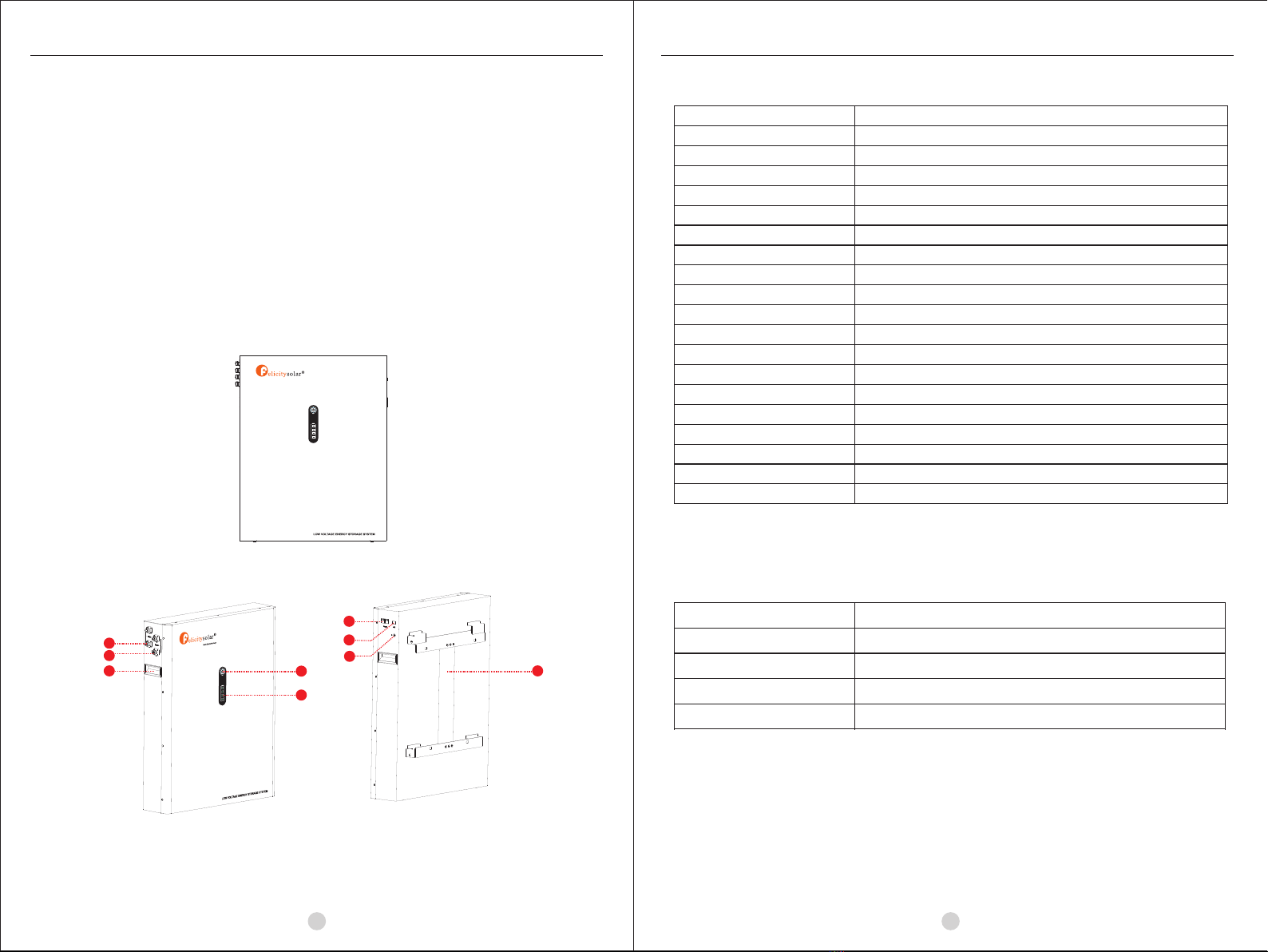
2.2 Product Over View
2.1 Features
03
LiFePO4 Battery System for Households
2.3 Specifications
2.4 Recommended Settings
Lithium battery pack is not same as lead-acid battery, so for the devices which you connect with the battery pack
for charging or discharging, such as inverters, MPPT charger controllers or UPS, please implement pre-settings
as recommended settings as below before you launched them.
Setting
Max. Charging Voltage
Floating charging Voltage
Max. Charging Current
Cut-off voltage
Notes: “N” means the number of battery packs connected in parallel.
LPBA48170
57.6V
57.6V
80A*N
48V
1. LED display 2. Power On/Charging indicator 3.Communication port
4.SW 5.Battery Positive + 6.Battery Negative -
7.Earth wire 8.Handle
48V Front view
Model
Usable Capacity
Nominal Voltage
Voltage Range
Recommend Charge Cut-off Voltage
Recommend Discharge Cut-off Voltage
MAX. Charge & Discharge Current
Recommend Charge&Discharge Current
MAX. Output Power
Recommend Output Power
DOD
Modules Connection
Communication
Ingress Protection
Cycle Life
Working Temperature Range
Net Weight(KG)
Product Dimension(MM)
≥95%
1~12 in parallel
CAN&RS485
IP21
≥6000@25°C, 80%DOD
Discharge:-20°C to +60°C, Charge:+0°C to +55°C
LPBA48170
8.7KWH
51.2
48-57.6
57.6
48
120A @10S
≤80A
6000W
4000W
Package Dimension(MM)
855x 700x330MM
Gross Weight(KG)
Make li fe full o f hope
1
2
3
4
6
5
9.Wall mounted fixing
8 9
7
70.5KG
81.5KG
755x600x160MM
04 05
LiFePO4 Battery System for Households
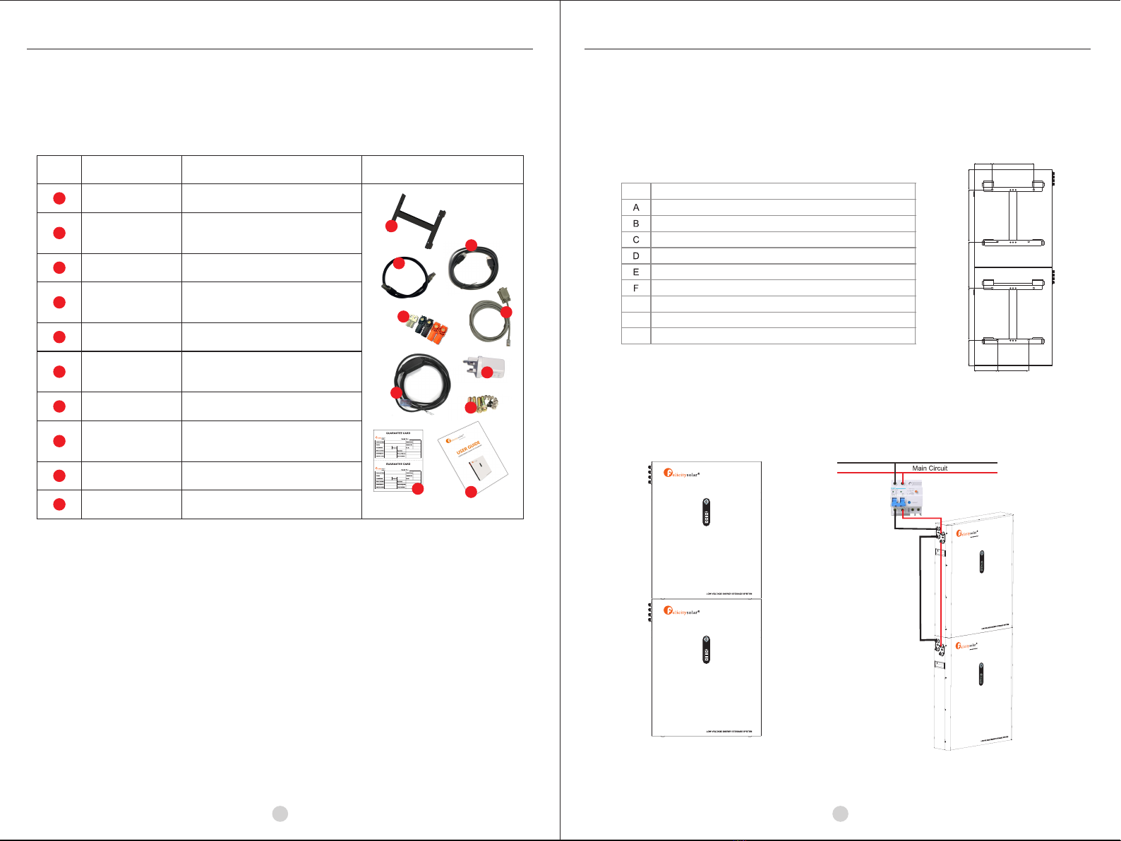
The LPBA battery support to be connected in parallel for expansion. If you need one more battery
bank work in parallel mode, connect the battery as shown in PIC 2
3.3 Connection for Parallel Mode
Step 2: The schematic diagram of the parallel
connection of two battery packs is shown in
Figure 2.
LiFePO4 Battery System for Households
Before installation, please inspect the unit. Be sure that nothing inside the package is damaged. You
should have received the following items inside of package.
3.1 Unpacking and Inspection
NO NAME SPECIFICATION PICTURE
Communication line 1
Communication line 2
Used for Communication among batteries
Adapter
Screw Mounting screw
PV Wake up line
User manual User manual
Guarantee card Guarantee card
6
2
1
4
5
6
7
33
2
8
Grid activation communication wire
( used with 6)
Used for activating the pack when grid
power recover
7
9
Used for auto restart when PV comeback
in off-grid system
3. INSTALLATION
10
8
4
Communication line 3 Used for communication between battery
and host computer
10
3.2 Mounting the Unit
Consider the following points before selecting where to install:
• Do not mount the battery on flammable construction materials.
• The ambient temperature should be between 0°C and 45°C to ensure optimal operation.
• The recommended installation position is to be adhered to the wall vertically.
• Be sure to keep other objects and surfaces as shown in the right diagram to guarantee sufficient heat dissipation and
to have enough space for removing wires.
AB
C
D
E
F
G
H I
LPBA48170
140
320
159
401
357
401
198
180
240
G
H
I
Step 1: The batteries are placed
as shown in Figure 1
Make life full of hope
Make life full of hope
9
1
Connector&Terminal Connector&Terminal
Wall mount Wall mount bracket
5

LiFePO4 Battery System for Households
0706
LiFePO4 Battery System for Households
Step 3: The schematic diagram of the parallel connection of six battery packs is shown in Figure 3.
Note: After completing the above 4 steps, arbitrarily select the positive and negative poles of one of the battery
packs to output (the upper battery pack or the lower battery pack, you can not select the positive and negative
poles of the two battery packs at the same time). After confirming the correct connection of the inverter, controller
and battery, you can turn on any of the switches and use the battery group happily.
Step 4: The communication terminal (the other end) is connected as shown in Figure 4. Only one communication line
(network cable) is required to connect through the hole between the two batteries. Another one is used as a backup.
Note: One group of LPBA48V can be stacked up to 6 layers, and up to 12 in parallel connection.
For pure off grid system ,the PV awake wire need to be connected with MPPT charge controller if the battery
pack is charged by solar panels only . The connection diagram as below :
48V Front view
Make life full of hope
Make life full of hope
Make life full of hope
Make life full of hope
Make life full of hope
Table of contents
Other Felicitysolar Camera Accessories manuals


Popular Camera Accessories manuals by other brands


Trojan
Trojan GC2 48V quick start guide

Calumet
Calumet 7100 Series CK7114 operating instructions

Ropox
Ropox 4Single Series User manual and installation instructions

Cambo
Cambo Wide DS Digital Series Main operating instructions

Samsung
Samsung SHG-120 Specification sheet

Ryobi
Ryobi BPL-1820 Owner's operating manual