Femi 240 Specification sheet

ISTRUZIONI PER L’USO E MANUTENZIONE / INSTRUCTIONS FOR USE AND
MAINTENANCE / GEBRAUCHSANLEITUNGEN UND WARTUNG / MODE D’EMPLOI ET
ENTRETIEN / INSTRUCCIONES PARA EL USO Y MANUTENCION / INSTRUÇÕES DE
UTILIZAÇÃO / GEBRUIK- EN ONDERHOUDSAANWIJZINGEN
www.femi.it
SMERIGLIATRICI, PULITRICI E LEVIGATRICI
GRINDERS, POLISHING AND BELT SANDING MACHINES
SCHLEIFMASCHINEN, POLIERMASCHINEN UND HONMASCHINEN
TOURETS, EBARBEUSES ET PONCESEUS
ESMERILLADORAS, LIMPIADORAS Y LIJADORAS
ESMERILADORAS, MAQUINAS DE POLIR E ALISADORAS
CERTIFICATA
CERTIFIED
GEPRÜFT
CERTIFIE
CERTIFICADA
CERTIFICADA


DICHIARAZIONE DI CONFORMITÁ CE DEL
COSTRUTTORE FEMI S.p.A.
Via del Lavoro, 4 - 40023 Castel Guelfo (BO) - ITALIA
Tel. +39-0542-670160 - Fax +39-0542-670185
Dichiara che la: SMERIGLIATRICE
è conforme alle disposizioni contenute nelle Direttive:
CEE 98/37 - 89/336 - 73/23
COMPLIANCE DECLARATION CE OF THE
BUILDER FEMI S.p.A.
Via del Lavoro, 4 - 40023 Castel Guelfo (BO) - ITALIA
Tel. +39-0542-670160 - Fax +39-0542-670185
Declare the: BENCH GRINDER
is in compliance with the rules contents in the
Directives:
EEC 98/37 - 89/336 - 73/23
CE KONFORMITATS ERKLARUNG DES
HERSTELLER FEMI S.p.A.
Via del Lavoro, 4 - 40023 Castel Guelfo (BO) - ITALIA
Tel. +39-0542-670160 - Fax +39-0542-670185
Erklart dass: SCHLEIFMASCHINE
ist konform mit der Direktiven:
EWG 98/37 - 89/336 - 73/23
DECLARATION DE CONFORMITE CE DU
CONSTRUCTEUR FEMI S.p.A.
Via del Lavoro, 4 - 40023 Castel Guelfo (BO) - ITALIA
Tel. +39-0542-670160 - Fax +39-0542-670185
Declare que la: TOURET A MEULER
est conforme aux disposition contenues dans les
Directives:
CEE 98/37 - 89/336 - 73/23
DECLARATION DE CONFORMIDAD CE DEL
CONSTRUCTOR FEMI S.p.A.
Via del Lavoro, 4 - 40023 Castel Guelfo (BO) - ITALIA
Tel. +39-0542-670160 - Fax +39-0542-670185
Declara que la: SMERILLADORA
esta conforme a las disposiciones contenide en la
Directivas:
CEE 98/37 - 89/336 - 73/23
DECLARAÇÃO DE CONFORMIDADE CE DO
CONSTRUTTORE FEMI S.p.A.
Via del Lavoro, 4 - 40023 Castel Guelfo (BO) - ITALIA
Tel. +39-0542-670160 - Fax +39-0542-670185
Declara que a: ESMERILADORA DE BANCADA
suivindo as regras exigidas no contendo da Directivas:
CEE 98/37 - 89/336 - 73/23
01 07
02 08
03 09
04 10
05 11
06 12
2006 2009
2007 2010
2008 2011
143/M
145/M
146/M
163/M
165/M
166/M
191/M
192/M
193/M
194/M
195/M
196/M
197/M
198/M
199/M
200/M
240/M
241/M
242/M
243/M
244/M
245/M
246/M
247/M
143
145
146
163
165
166
191
192
193
194
195
196
197
198
199
200
201
202
203
204
208
209
211
213
214
240
241
242
243
244
245
246
247
282
296
298

ITALIANO (IT) ................................................................................................................ 5 ÷ 9
ENGLISH (EN) .............................................................................................................. 7 ÷ 12
DEUTSCH (DE) .......................................................................................................... 13 ÷ 18
FRANCAIS (FR) ......................................................................................................... 19 ÷ 24
ESPANOL (ES) .......................................................................................................... 25 ÷ 30
PORTUGUÊS (PT) ..................................................................................................... 31 ÷ 36
INDICE/ INDEX / INHALT / INDEX / INDICE / ÍNDICE

5
IT
1 INTRODUZIONE ALL’USO .................................... 5
2 INSTALLAZIONE ...................................................... 6
3 REGOLAZIONI ........................................................ 7
4 MANUTENZIONE ..................................................... 9
INDICE
1 INTRODUZIONE
Leggete attentamente queste istruzioni allo scopo di
conoscere la macchina ed i suoi impieghi, e le eventuali
controindicazioni.
Conservate con cura questo manuale: esso fa parte
integrante della macchina, e ad esso dovrete sempre riferirvi
per eseguire al meglio e nelle massime condizioni di sicurezza
le operazioni che in esso sono descritte.
Utilizzate la macchina solo ed esclusivamente per gli
impieghi di seguito specificati, usandola come
raccomandato in questo manuale, e non cercando in alcun
modo di manometterla o forzarla, o di usarla per scopi non
adatti.
1.1 SIMBOLOGIA
Non sottovalutare i richiami “ATTENZIONE - CAUTELA”
riportati in questo manuale.
Al fine di attirare l’attenzione e dare messaggi di sicurezza
le operazioni pericolose sono precedute da simboli e note
che ne evidenziano la pericolosità e spiegano come
comportarsi per evitare il pericolo.
Questi simboli e note sono di tre categorie identificate dalle
parole:
ATTENZIONE: comportamenti rischiosi che
potrebbero provocare gravi lesioni.
CAUTELA: comportamenti che potrebbero causare
lesioni non gravi o danni alle cose.
NOTE: le note precedute da questo simbolo sono di
carattere tecnico e facilitano le operazioni.
1.2 SICUREZZA E NORMATIVA
La macchina è progettata e costruita secondo le prescrizioni
imposte dalle vigenti Direttive Comunitarie :
CEE 98/37 - CEE 73/23 - CEE 89/336
La dichiarazione di conformità CE allegata, unita al marchio
CE posto sul prodotto, costituisce elemento fondamentale
e parte integrante della macchina : garantiscono la
conformità del prodotto alle Direttive di sicurezza sopra
citate.
1.3 TIPO DI IMPIEGO
Questa macchina è stata ideata e costruita per operazioni
di asportazione di materiale, come smerigliatura o affilatura
di utensili, su qualsiasi tipo di metallo.
La versione combinata o pulitrice è dotata di sbraccio
dell’albero rispettivamente su uno o due lati, atto ad
accogliere spazzole di vario tipo (a filo di acciaio, a lamelle
abrasive o di tessuto) per la pulitura ai vari livelli dei metalli
di qualsiasi tipo.
Evitate di usare la macchina per qualsiasi altro tipo di
impiego che non sia previsto in queste istruzioni.
1.4 NORME DI SICUREZZA
- Non usate la macchina all’aperto, in luoghi molto umidi
o con presenza di liquidi infiammabili o di gas.
- Abbiate cura di posizionare la macchina in una zona di
lavoro sufficientemente illuminata: ciò è di importanza
fondamentale nella prevenzione degli infortuni.
- Non forzate inutilmente la macchina: una pressione
eccessiva può provocare un rapido deterioramento delle
mole, un peggioramento delle prestazioni della macchina
ed un dannoso surriscaldamento del motore.
- Ogni volta che finite una operazione, spegnete la
macchina posizionando sullo “O” l’interruttore.
- Evitate di indossare abiti con maniche larghe od oggetti,
come sciarpe, catene o bracciali, che potrebbero essere
agganciati dalle parti in movimento.
- Usate sempre i dispositivi personali di protezione:
occhiali antinfortunistici conformi alle norme, cuffie o
inserti auricolari e cuffie per il contenimento dei capelli,
se necessario.
- Fate attenzione al cavo di alimentazione: non usatelo
per sollevare la macchina o per staccare la spina dalla
presa, e salvaguardatelo da spigoli vivi, oli e zone con
elevate temperature.
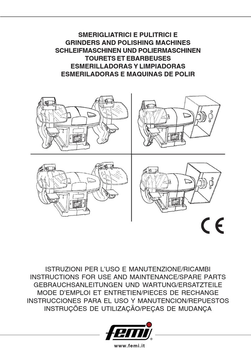
1.5 DESCRIZIONE DELLA MACCHINA
-(Fig. 1a: smerigliatrice)
-(Fig. 1b: smerigliatrice combinata)
-(Fig. 1c: pulitrice)
-(Fig. 1d: smerigliatrice/levigatrice)
1. CORPO MACCHINA
2. INTERRUTTORE ON/OFF
3. MOLAABRASIVA
4. PARASCINTILLE TRASPARENTE
5. CUFFIA DI PROTEZIONE
6. POGGIAPEZZI

6
IT
7. PARASCHEGGE REGOLABILE
8. FORI PER IL FISSAGGIO
9. PROTEZIONE SPAZZOLA
10. SBRACCIO ALBERO
11. PULSANTE DI ARRESTO DI EMERGENZA
12. NASTRO ABRASIVO
13. RUOTAGOMMATA
1.6 RIMOZIONE DELL’IMBALLO, STOCCAGGIO
E TRASPORTO
Rimozione dell’imballo
Togliete la macchina dall’imballo che la protegge durante il
trasporto, avendo cura di conservare la scatola integra,
nel caso dobbiate successivamente trasportarla da un posto
di lavoro ad un altro, oppure se dovete immagazzinarla per
lunghi periodi.
Movimentazione e trasporto
Se la macchina è dotata di basamento, occorre prima
separarla da questo, rimuovendo i dadi di fissaggio.
ATTENZIONE: Le macchine con potenza
superiore o uguale a 1100 Watt, dato il loro
rilevante peso, dovranno essere sollevate e
posizionate nel posto di lavoro scelto, oppure
trasportate da un posto di lavoro ad un altro,
da almeno due persone.
Le macchine di potenza inferiore, dato il loro peso contenuto,
possono essere sollevate e movimentate anche da una
sola persona.
Stoccaggio
Nel caso dobbiate immagazzinare la macchina, fate
attenzione agli ideogrammi stampati sulla scatola, per evitare
schiacciamenti della stessa per sovraccarico o cadute per
scarsa stabilita’ del carico.
2 INSTALLAZIONE (Fig. 1a)
Posizionamento sul posto di lavoro (Fig. 2)
CAUTELA: Abbiate cura di posizionare la
macchina in una zona di lavoro adeguata sia
come condizioni ambiente che come
luminosità: ricordate sempre che le condizioni
generali dell’ambiente di lavoro sono
fondamentali nella prevenzione degli infortuni.
Posizionate la macchina su un banco sufficientemente
piano in modo da avere la migliore stabilità possibile.
L’altezza ideale del banco deve essere quella che vi
consente di posizionare il poggiapezzi 6a circa un metro da
terra.
Fissaggio della macchina al banco di lavoro (Fig. 2)
Vi consigliamo di fissare la macchina al banco di lavoro,
inserendo quattro viti M6 nei fori 8e bloccandole dalla
parte opposta con gli appositi dadi.
Montaggio della macchina sul basamento (dove
previsto)
Per fissare la macchina al basamento utilizzare gli accessori
in dotazione con lo stesso facendo corrispondere i fori 8
della macchina con i rispettivi fori sul piano superiore di
appoggio del basamento.
Fissaggio del basamento a terra
Se la macchina è fornita completa di basamento, oppure
se il basamento viene fornito successivamente, è buona
norma fissarlo al pavimento mediante gli appositi fori
presenti sul piano di appoggio inferiore, e riempirlo di sabbia,
in modo da rompere eventuali vibrazioni e renderlo più
stabile.
Montaggio degli accessori (Fig. 1a-2)
Prendete dal sacchetto contenuto nell’imballo i parascintille
trasparenti 4, i paraschegge regolabili 7(dove presenti) e i
poggiapezzi 6ed assemblateli sulle cuffie di protezione 5
tramite le viti contenute nel sacchetto stesso, come
mostrato in (figura 2).
2.1 COLLEGAMENTO ELETTRICO
Messa a terra
Accertatevi che l’impianto rete sul quale inserite la macchina
sia collegato a terra come previsto dalle norme di sicurezza
vigenti, e che la presa di corrente sia in buono stato.
Montaggio della spina
Collegate all’estremità del cavo rete della macchina una
spina omologata secondo le normative di sicurezza, facendo
attenzione ad inserire il conduttore di protezione giallo verde
nell’apposito morsetto contrassegnato.
SOLO PER MACCHINE TRIFASE: il senso di rotazione
dell’albero motore deve essere quello indicato dalle frecce
sulle cuffie di protezione; in caso contrario, invertite tra di
loro due dei tre fili di fase nella spina.
Scelta della protezione magnetotermica
Si ricorda all’utilizzatore che a monte dell’impianto rete deve
sempre essere presente una protezione magnetotermica
atta a salvaguardare tutti i conduttori dai cortocircuiti e dai
sovraccarichi.
Tale protezione dovrà essere scelta in base alle
caratteristiche elettriche della macchina, specificate nella
targhetta dei dati ad essa applicata.
2.2 INFORMAZIONI RELATIVE AL RUMORE
Le smerigliatrici determinano, nelle normali condizioni di
utilizzo descritte in queste istruzioni, un livello equivalente
di pressione acustica:
Leq = 60 dB(A) nel funzionamento a vuoto;
Leq = 77 dB(A) durante le lavorazioni (es.
smerigliatura di un tondino di acciaio
C 40).
Le rilevazioni sono state effettuate secondo le Norme
UNI 7712, ISO 3740, ISO 3746, e CEE 89/392.
E’ comunque raccomandato l’uso dei mezzi personali di
protezione dell’udito, come cuffie o inserti auricolari.

7
IT
2.3 INFORMAZIONI SULLA COMPATIBILITA’
ELETTROMAGNETICA
Le recenti Normative Europee sulla sicurezza, ed in
particolare la Direttiva CEE 89/336, prescrivono che tutte
le apparecchiature siano dotate di dispositivi di schermatura
per i radiodisturbi sia da che verso l’ambiente esterno.
Questa macchina è conforme alle prescrizioni.
Le prove sono state eseguite secondo le Norme EN
55011, EN 55014, EN 50082-1, IEC 1000-4-2, IEC 1000-4-
4.
3 REGOLAZIONI (Fig. 2-3)
Le normative antinfortunistiche internazionali prescrivono
che il paraschegge regolabile 7e il poggiapezzi 6siano
posizionati a non più di 2 mm. dal bordo periferico della
mola.
Con il consumo la mola diminuisce di diametro, e queste
distanze vengono incrementate.
Controllate periodicamente il loro valore e, se aumentato,
riconducetelo nei limiti prescritti regolando gli accessori 7
ed 6tramite le loro viti di fissaggio.
3.1 UTILIZZO DELLA MOLA (Fig. 4-8)
Inserite la spina del cavo di alimentazione nella presa di
corrente dell’impianto rete.
Mettete in funzione la macchina azionando il pulsante verde
14 dell’interruttore 2.
ATTENZIONE: INDOSSATE SEMPRE GLI
OCCHIALI DI PROTEZIONE.
Per controllare il senso di rotazione, azionate a piccoli impulsi
l’interruttore 2, in modo che la macchina non raggiunga il
massimo regime di rotazione; se il senso di rotazione non è
quello indicato dalle frecce sulle cuffie di protezione,
arrestate la macchina e provvedete alla modifica del
collegamento delle fasi nella spina (vedi “COLLEGAMENTO
ELETTRICO”).
Mettete a contatto dolcemente il pezzo da lavorare con la
mola, appoggiandolo al poggiapezzi 6, ed applicate uno
sforzo progressivo, senza tuttavia premere
eccessivamente, per evitare che la macchina perda il
normale regime di giri.
CAUTELA: Il pezzo da lavorare deve sempre
essere tenuto con entrambe le mani, e di tanto
in tanto raffreddato in una vaschetta con acqua.
La mola di destra è di grana più grossa essa è più indicata
per operazioni di sgrossatura.
La mola di sinistra è di grana più fine, ed è indicata
maggiormente per finitura ed affilatura di utensili.
Per fermare la macchina, premere il pulsante rosso 15
dell’interruttore 2oppure premere il pulsante di arresto di
emergenza 11 (Fig. 9).
3.2 UTILIZZO QUADRO COMANDI (Fig. 10)
(di serie per macchine 2.200 Watt, a richiesta per tutte le
altre)
Per mettere in funzione la macchina, premere il pulsante
32 del quadro comandi.
Per arrestare la macchina, premere il pulsante di arresto a
fungo 33.
Per rimettere in funzione la macchina, sbloccare il pulsante
a fungo 33 ruotandolo in senso orario, e premere di nuovo
il pulsante 32.
3.3 SOSTITUZIONE DELLA MOLA (Fig. 2-5-6)
ATTENZIONE: prima di eseguire le operazioni
di manutenzione, sezionare l’alimentazione
elettrica.
Azionate l’interruttore 2fermando la macchina, ed attendete
che le mole abrasive siano perfettamente ferme.
Smontate gli accessori 7 ed 6.
Rimuovete il coperchio 16 della cuffia di protezione,
svitando le relative viti.
Con una chiave aperta, svitate il dado 17, usando una
chiave esagonale inserita nella sede ricavata all’estremità
dell’albero per tenere fermo lo stesso.
Tenete presente che dal lato sinistro il dado ha filettatura
sinistrorsa, quindi si svita in senso orario.
Sostituite la mola usurata con una nuova.
Controllo dell’integrità di una mola nuova
Prima di montare la mola nuova, è bene sottoporla ad una
prova del suono onde verificarne l’integrità.
Per effettuare questa prova, le mole dovranno essere
asciutte e pulite, altrimenti il suono emesso potrebbe risultare
smorzato.
Con l’aiuto di uno strumento non metallico (manico in legno
di un cacciavite oppure mazzuolo in legno) battete
leggermente la mola sulla parte laterale (Fig. 5): un leggero
colpo su una mola integra dà un suono pulito e gradevole.
Se il suono emesso è invece sordo o incrinato, la mola non
dovrà essere utilizzata.
Riavvitate il dado 17 (Fig. 6).
Rimontate il coperchio 16 della cuffia di protezione.
Riassemblate gli accessori smontati in precedenza.
Se il movimento radiale ed assiale della mola in rotazione,
misurati rispettivamente sulla circonferenza e sulla parete
laterale della mola, risulta troppo elevato, la mola produce
vibrazioni eccessive durante l’uso al massimo regime di
rotazione.
Per diminuire tale valore, arrestate la macchina, allentate
la mola e ruotatela di un quarto di giro sul proprio asse
tenendo fermo l’albero motore, poi ribloccatela; se non
dovesse modificarsi alcunchè, ripetete l’operazione più volte
fino a trovare la migliore posizione possibile.
3.4 UTILIZZO DELLA SPAZZOLA (Fig. 7)
La parte destra della smerigliatrice combinata (oppure destra
e sinistra nelle pulitrici) è costruita in modo da potere
alloggiare una spazzola per la pulitura o lucidatura di metalli
di vario tipo.

8
IT
Possono essere montate spazzole a filamento metallico
(pulitura) oppure spazzole di panno o tessuto (lucidatura)
con diametro massimo, larghezza massima e foro del collare
di tenuta variabili a secondo del modello (vedi tabella
“IMPIEGO DEGLI UTENSILI APPROPRIATI”).
Controllate sempre che il diametro del collare centrale 18
che tiene insieme i filamenti sia maggiore del diametro
delle flange di fissaggio 19 presenti sulla macchina.
ATTENZIONE: E’ vietato fissare le spazzole con
le flange direttamente in presa sui filamenti.
Controllate di tanto in tanto lo stato generale della spazzola
mediante esame a vista, soprattutto per quanto concerne
la tenuta dei filamenti tramite il collare centrale: se doveste
verificare che il collare non chiude più bene, non esitate a
sostituire la spazzola con una nuova.
Montaggio della spazzola
ATTENZIONE: prima di eseguire le operazioni
di manutenzione, sezionare l’alimentazione
elettrica.
Assicuratevi che la macchina sia spenta e che gli utensili
già presenti (es. mole) siano perfettamente fermi.
Svitate con chiave esagonale il dado 20 che serra le flange
sull’albero.
Estraete la flangia di serraggio 19 dalla sua sede.
Inserite la spazzola sull’albero, controllando che il foro della
stessa sia uguale al diametro dell’albero o della boccola di
riduzione in dotazione su cui va fissata.
Riposizionate la flangia di serraggio 19 sull’albero mettendola
a contatto con il collare della spazzola 18.
Togliete il tappo laterale centrale 21 dalla protezione, ed
introducete dal foro una chiave a brugola fino all’inserimento
nella sede sull’albero 22.
A questo punto, tenendo bloccato l’albero con al chiave a
brugola, serrate il dado di fissaggio sulle flange.
Provate a ruotare a mano la spazzola per verificare la sua
centratura; nel caso dovesse essere difettosa, provvedete
a ripetere le fasi sopra descritte.
3.5 UTILIZZO DEL NASTRO ABRASIVO (Fig. 11)
La parte destra delle smerigliatrici/levigatrici (oppure destra
e sinistra delle levigatrici) alloggia un nastro abrasivo per la
smerigliatura e la levigatura di metalli di vario tipo.
Sono disponibili su richiesta nastri di diverse grane abrasive
(40, 60, 80) secondo il tipo di lavorazione necessaria (a
numero di grana più basso corrisponde maggiore capacità
di asportazione).
Potete utilizzare il nastro abrasivo sia sul piano di appoggio
23 che sulla ruota gommata 24.
Uso del piano di appoggio
Per utilizzare il piano di appoggio, regolate l’apertura della
protezione scorrevole 25, alzandola o abbassandola in modo
da lasciare scoperta solo la parte necessaria al passaggio
del particolare da lavorare.
Verificate che lo squadro 26 sia posizionato ad una distanza
non superiore a 2 mm. dalla superficie del nastro, ed
utilizzatelo come appoggio per sostenere il particolare.
Lo squadro 26 è regolabile anche come inclinazione, per
permettervi di sagomare i pezzi come voluto.
mm
/
150x25x16
150x25x16
/
200x25x16
200x25x16
/
200x30x20
/
250x40x20
250x40x20
/
300x60x25
300x60x25
/
/
ARTICOLO
(*)
240-241-191
244-245-196
282-208-201
242-243-192
246-247-197
213-214-204
143-193
163-198
145-194
165-199
209-202
146-195
166-200
211-203
296
298
mm.
150x25x16
150x25x16
/
200x25x20
200x25x20
/
200x30x20
200x30x20
250x35x25
250x35x25
/
300x40x30
300x40x30
/
200x25x20
/
mm
/
/
/
/
/
/
/
/
/
/
/
/
/
/
50x2200
50x2200
NOTA: (*) sono compresi anche gli articoli nella
versione M.
Uso della ruota gommata
Per utilizzare la ruota gommata, chiudete completamente
la protezione scorrevole 25, ed aprite la protezione mobile
27, svitando la relativa vite di fissaggio.
A questo punto potete utilizzare la ruota gommata come
fosse una comune mola abrasiva, con il vantaggio offerto
dalla possibilità di potere orientare il pezzo da lavorare in
tutte le direzioni possibili.
3.6 SOSTITUZIONE DEL NASTRO ABRASIVO
(Fig. 11)
ATTENZIONE: prima di eseguire le operazioni
di manutenzione, sezionare l’alimentazione
elettrica.
Assicuratevi che la macchina sia spenta e che gli utensili
presenti (mola, nastro) siano fermi.
Svitate i due volantini 28, ed aprite il carter laterale 29.
Sbloccate la leva di tensionamento 30, e sfilate il nastro
abrasivo dalle due ruote.
Posizionate il nuovo nastro al centro delle due ruote, e
rimettetelo in tensione azionando la leva 30.
3.7 CENTRAGGIO DEL NASTRO ABRASIVO (Fig.
8-11)
Azionate a piccoli impulsi il pulsante verde 14 dell’interruttore
2, controllando che il nastro rimanga perfettamente
posizionato al centro delle due ruote.
Per correggere eventuali spostamenti laterali del nastro,
ruotate lievemente il volantino di centraggio 31 posto nella
parte superiore del gruppo nastro, tenendo presente che a
rotazione oraria corrisponde spostamento laterale verso
destra del nastro.
IMPIEGO DEGLI UTENSILI APPROPRIATI

9
IT
2002/96/EC
3.8 ASPIRAZIONE E RACCOLTA DELLE POLVERI
La macchina è dotata di bocche per lo scarico delle polveri
sia nelle cuffie di protezione delle mole (smerigliatrici) che
nelle protezioni spazzola (combinate e pulitrici) e nastro
abrasivo.
E’ quindi possibile dotarla di impianto di aspirazione delle
polveri, richiedendo al vostro rivenditore di fiducia
l’aspiratore completo di accessori di collegamento e di
sacco raccoglipolvere, per mantenere la salubrità e la pulizia
nell’ambiente di lavoro.
4 MANUTENZIONE
Le normali operazioni di manutenzione ordinaria, effettuabili
anche da personale non specializzato, sono tutte descritte
nei paragrafi precedenti e nel presente.
Nel caso sia necessario l’intervento di personale qualificato
per operazioni di manutenzione straordinaria, oppure in caso
di riparazioni, sia in regime di garanzia che
successivamente, rivolgetevi sempre ad un centro di
assistenza autorizzato, oppure direttamente alla fabbrica,
se nella vostra regione non è presente il centro di
assistenza.
4.1 SMALTIMENTO MACCHINA, IMBALLAGGIO
Quando si rende necessario, alla fine
del normale ciclo di funzionamento,
rottamare la macchina, essa dovrà
essere conferita ad un Centro di
raccolta e smaltimento dei rifiuti
autorizzato al fine di rispettare le
Norme per l’igiene e la salvaguardia
dell’ambiente.
Anche l’imballaggio va smaltito
secondo le normative vigenti, conferendolo a soggetti
autorizzati alla raccolta ed allo smaltimento o al recupero.
Rivolgetevi quindi al CONSORZIO DEGLI OLI USATI PIU’
VICINO.

EN
10
1 INTRODUCTION TO USE .................................... 10
2 INSTALLATION ....................................................... 11
3 ADJUSTMENT ........................................................ 12
4 MAINTENANCE ...................................................... 14
INDEX
1 INTRODUCTION
Please read these instructions carefully in order to learn
how to use this machine and how to deal with any
contraindications. Keep these instructions in a safe place:
they are an integrating part of the machine.
This instruction manual is an integral part of the machine
and therefore must be kept complete and handled with
care. Always refer to the contents reported in this manual
for carrying out all the operations required for using the
machine to the best advantage and under utmost safety
conditions.
Use the machine solely and exclusively for the uses
outlined below, as recommended in this manual, and do not
attempt to tamper with it, force it or use it for other purposes.
1.1 CONVENTIONAL SYMBOLS
Never underestimate the warnings "ATTENTION -
CAUTION" given in this manual.
In order to draw the user's attention and to preserve safety,
hazardous operation are preceded by symbols and notes
that point out the danger and explain how to behave to
avoid any risk.
These symbols and notes are divided in three categories,
identified by the following words:
WARNING: dangerous-behaviours that could
cause serious injuries.
CAUTION: behaviours that could cause slight
injuries or damages to things.
NOTE: the notes preceded by this symbols are
technical and are aimed at making operations
easier.
1.2 STANDARDS ON SAFETY
The machine has been designed and manufactured
conforming to the norms set forth by the following prevailing
Machinery Directives: EEC 98/37 - EEC 73/23 - EEC 89/
336
The annexed CE Declaration of Conformity, together with
the CE mark attached to the product, constitute an essential
element and are an integral part of the machine: they
guarantee that the product duly conforms to the aforesaid
safety Directives.
1.3 TYPE OF USE
This machine has been conceived and manufactured to
remove material, such as tool grindings or lappings, from
any type of metal.
In the bench grinder and polishing machine (combined
version) the shaft is fitted with an extension on one or both
sides, where it is possible to fit several types of brushes
(such as with steel wires, with abrasive blades or in fabric)
suitable for any type of metal.
Avoid using it for any other type of use that is not foreseen
by these instructions.
1.4 SAFETY REGULATIONS
- Do not use the machine outdoors, in humid places or in
the presence of gas or flammable liquids.
- Put the machine in a well lit working area: this is
extremely important in preventing work accidents.
- Do not force the machine unnecessarily: excessive
pressure could cause the grinding wheel to deteriorate
very quickly, the machine’s performances could worsen
and the motor be damaged by overheating.
- Each time a machine operation is finished, turn off the
machine switching it to position “O”.
- Avoid wearing loose-sleeved work clothes or
accessories such as scarves, neck-chains or bracelets
which could be hooked by the moving parts.
- Always use protection devices: accident prevention
eyeglasses as foreseen by regulations, headsets or
earphones and if necessary, caps to hold back loose
hair.
- Do not use the electric feeding cable to lift the machine
or to take off the plug from the current tap. Avoid
contact with sharp edges, oils and high temperatures.
1.5 DESCRIPTION OF THE MACHINE
-(Picture 1a: bench grinder)
-(Picture 1b: combined bench grinder)
-(Picture 1c: polishing machine)
-(Picture1d: bench grinder/sander)
1. MACHINE BODY
2. TURNING-ON SWITCH
3. ABRASIVE GRINDING WHEEL
4. TRANSPARENT SPARK ARRESTERS
5. SAFETY CAP
6. PIECE-REST

EN
11
7. ADJUSTABLE CHIP GUARDS
8. KEEPER HOLES
9. BRUSH PROTECTION
10. SHAFT EXTENSION
11. EMERGENCY STOP BUTTON
12. SAND BELT
13. RUBBER-COATED WHEEL
1.6 PACKING REMOVAL, STORAGE and
TRANSPORT
Packing removal
If the machine is fit with a base, first separate it from the
machine by removing the fastening screw nuts.
Remove the machine from the packing that protects it
during transport. Please do not throw the box away, it could
be useful in case you will have to displace the machine or
need to store it for long periods.
Displacement and transport
WARNING: The machines with more than 1100
Watt are very heavy and must therefore be lifted
and positioned on the choosen working place.
Otherwise they have to be displaced by at least
two people.
Machines with a lower power can be lifted and displaced by
one person only.
Storage
Should you have to store the machine, please take into
account the ideograms printed on the box. Do not crush
the box with overloads and put it in a safe position so that
it does not fall.
2 INSTALLATION (Picture 1a)
Positioning in working area (Picture 2)
CAUTION: Ensure that the machine is located
in a suitable area both as far as work
environment and lighting are concerned: always
keep in mind that the overall work environment
conditions are essential for preventing
accidents.
Position the machine on a sufficiently flat bench so as to
have the best stability possible.
The ideal height of the bench is that allowing the positioning
of the piece-rest 6at about one meter from the ground.
Machine fastening on working table (Picture 2)
We recommend to secure the machine to the work bench,
by inserting four M6 screws in holes 8, locking them on the
opposite side using the appropriate screw nuts.
Machine fastening on the column (where foreseen)
In order to secure the machine to the base, use the standard
fittings provided. Match holes 8of the machine with the
corresponding holes in the upper support surface of the
base.
Securing the base to the floor
The column (if delivered with the machine) has to be fixed
to the floor through the special holes on its lower part.
Furthermore fill it with sand to avoid vibrations and in order
to increase its stability.
Fitting of auxiliary equipment (picture 1a-2)
From the bag inside the packaging take out the adjustable
chip guards 7, the transparent spark arresters 4 and the
piece-rests 6and assemble them onto the safety caps 5
using the screws inside the same bag, as shown in (picture
2).
2.1 ELECTRIC CONNECTION
Grounding
Check that the power grid to which the machine is plugged
in is grounded as foreseen by the safety rules in force,
and that the current socket is in good condition.
Plug fitting
Connect a plug in compliance with safety regulation to the
end of the mains cable of the machine, check that the
yellow/green protective conductor is fitted into the relative
terminal.
ONLY FOR THREE-PHASE MACHINES: the direction of
rotation must be that indicated by the arrow on the protection
caps. Otherwise reverse the position of two of the three
wires in the plug.
Choice of the thermal protection
We remind the user that a magnetothermic protection, fit
for safeguarding all the conductors from short-circuits and
overloads, must always be placed before the power grid.
Said protection is to be chosen according to the electric
specifications of the machine, indicated on the data plate
applied to it.
2.2 NOISE RELATED INFORMATION
Under normal working conditions as described in these
instructions, the grinding machines bring about a level of
acoustic pressure corresponding to:
Leq =60 dB (A) when idling;
Leq =77 dB (A) during workings (for example: lapping
a C 40 steel rod)
Tests were carried out according to UNI 7712, ISO 3740,
ISO 3746 and CEE 89/392 regulation.
It is however recommended to use personal means for
hearing protection, such as headsets or earphones.

EN
12
2.3 ELECTROMAGNETIC COMPATIBILITY
INFORMATION
The recent European Safety Standards, especially EEC
Directive 89/336, set forth that all the equipment must be
fit with radio interference suppressors both to and from the
outside environment.
This machine conforms to such Standards.
Tests were carried out according to EN 55011, EN 55014,
EN 50082-1, IEC 1000-4-2, IEC 1000-4-4 regulations.
3 ADJUSTMENTS (Picture 2-3)
The international safety rules prescribe that the adjustable
chip guards 7and the piece-rest 6are to be positioned not
more than 2 mm. from the peripheral edge of the grinding
wheel.
As the grinding wheel wears out, its diameter decreases,
and these distances are then increased.
Periodically check their values and, if they have increased,
reduce them within the fixed limits by adjusting accessories
7and 6by means of their fastening screws.
3.1 USE OF THE GRINDING WHEEL (Picture 4-
8)
Insert the input cable plug into the current socket of the
power grid.
Start running the machine by pressing the green pushbutton
14 of switch 2.
WARNING: ALWAYS WEAR ACCIDENT
PREVENTION EYEGLASSES.
In order to check the rotating direction, activate switch 2
by means of slight impulses so that the machine will not
rotate at maximum capacity. If the rotating direction is not
the one indicated by the arrows on the safety hoods, stop
the machine and change the phase connections in the plug
(see “ELECTRICAL CONNECTION”).
Gently bring the piece to be worked in contact with the
grinding wheel, laying it on piece-rest 6, and start applying
pressure progressively, but without pushing too hard, so
that the machine will not lose the normal r.p.m.
CAUTION: The piece being worked on must
always be held with both hands, and cooled
every now in a tank of water.
The grinding wheel on the right is of a thicker grain: it is
more suitable for chipping operations.
The left grinding wheel is of a thinner grain, and is more
suitable for finishing and grinding tools.
In order to stop the machine, press the red pushbutton 15
of switch 2or press the emergency stop button 11 (Picture
9).
3.2 USE OF THE CONTROL PANEL
(standard fitting for 2.200W machines, on request for all
the other machines)
In order to start the machine, press pushbutton 32 on the
control panel.
In order to stop the machine, press the emergency
mushroom-shaped button 33.
In order to restart the machine, release the emergency
mushroom-shaped button 33 turning it clockwise and then
press pushbutton 32 again.
3.3 REPLACING THE GRINDING WHEEL
(Pictures 2-5-6)
WARNING: Prior to performing any maintenance
operation, disconnect the electric power supply.
Activate switch 2 to stop the machine and wait until the
grinding wheels have stopped completely.
Take away parts 7and 6.
Remove cover 16 from the safety cap, unscrewing the
relevant screws.
With an open key unscrew the nut 17 and keep the shaft
steady through an hexagonal key, keeping in mind that on
the left side it has a left-handed threading, and therefore it
is unscrewed in clockwise direction.
Replace worn out grinding wheel with a new one.
Check if a new grinding wheel is integral
Before mounting the new grinding wheel, it is advisable to
perform a sound test in order to check its integrity.
To carry out this test, the grinding wheels must be dry and
clean, otherwise the emitted sound could result dampened.
With the help of a non-metallic tool (wooden handle of a
screwdriver or a wooden mallet), lightly strike the grinding
wheel on its side (Picture 5): a light strike against an
integral grinding wheel produces a pleasant and clear sound.
If, on the other hand, the emitted sound is dull or cracked,
the grinding wheel should not be used.
Retighten 17 (Picture 6) screw nut.
Reassemble cover 16 of the safety cap.
Re-assemble the pieces that were taken off previously.
If the radial and axial movement of the rotating grinding
wheel, gauged both on the circumference and on the side
wall of the grinding wheel respectively, should be too much,
the grinding wheel produces excessive vibration when used
at maximum rotating capacity.
In order to decrease such value, stop the machine, loosen
the grinding wheel and turn it on its axis by 1/4 turn holding
the motor shaft firmly, then lock the grinding wheel. If the
problem persists, repeat the operation as many times as
required until the best possible position is found.
3.4 USE OF THE BRUSH (Picture 7)
The right-hand part of the combined bench grinder (or right-
hand and left-hand in the polishing machines) is
manufactured so that it can house a brush for the cleaning
or polishing of various types of metals.
It is possible to fit metal wire brushes (cleaning) or cloth/
fabric brushes (polishing) with varying maximum diameter,
maximum width and stop collar hole, depending on the

EN
13
model (refer to the “USE OF APPROPRIATE TOOLINGS”
table).
Ensure that the diameter of the middle collar 18 that keeps
the wires together is always greater than the diameter of
the fastening flanges 19 provided on the machine.
WARNING: It is prohibited to secure the brushes
with the flanges in direct contact with the wires.
Every now and then check the general condition of the
brush by visually inspecting it, especially as concerns the
hold of the wires, by means of the middle collar. If you
notice that the collar does not close perfectly any more,
replace the brush with a new one at once.
Fitting of the brush
WARNING: Prior to performing any maintenance
operation, disconnect the electric power supply.
Ensure that the machine is OFF and that the toolings
provided (e.g. grinding wheels) are perfectly still.
Use an Allen wrench to unscrew the screw nut 20 that locks
the flanges to the shaft.
Remove the tightening flange 19 from its seat.
Fit the brush onto the shaft , ensuring that the hole of the
brush has the same diameter of the shaft or of the adapting
bush provided onto which it is secured.
Re-position the tightening flange 19 onto the shaft making
it touch the collar 18 of the brush.
Remove the middle side plug 21 from the protection and
introduce a socket wrench through the hole until the seat is
properly fit on the shaft 22.
At this point, keeping the shaft locked by means of the
socket wrench, tighten the fastening screw nut on the
flanges.
Try to turn the brush by hand to make sure that it is
centered. If it does not turn properly, repeat the aforesaid
steps.
3.5 USE OF THE SAND BELT
The right-hand side of the bench grinders/sanders (or right-
and left-hand sides of the sanders) houses a sand belt for
the grinding and sanding of various types of metals.
Belts with different sanding grains (40, 60, 80) are available
on request according to the type of required machining
(the lower the grain number, the greater the removal
capacity).
It is possible to use the sand belt both on the work table 23
and on the rubber-coated wheel 24.
Use of the work table
In order to use the work table, adjust the opening of the
sliding guard 25, raising it or lowering it so as to uncover
only the section required for passing the part to be
machined.
Ensure that the angle plate 26 is set not more than 2 mm.
from the belt’s surface and use it as a support for sustaining
the part.
The tilting of angle plate 26 can be adjusted for shaping the
parts as desired.
Use of the rubber-coated wheel
In order to use the rubber coated-wheel, fully shut the
sliding guard 25 and open the mobile guard 27, unscrewing
the associated fastening screw.
Now the rubber coated-wheel may be used as if it were a
normal grinding wheel with the advantage that the part to
be machined can be oriented in any direction.
3.6 SAND BELT REPLACEMENT (Picture 11)
WARNING: Prior to performing any maintenance
operation, disconnect the electric power supply.
Make sure that the machine is OFF and that the toolings
present (grinding wheel, belt) are in standstill.
Unscrew the two handwheels 28 and open the side guard
29.
Release the tensioning lever 30 and remove the sand belt
from the two wheels.
Position the new belt in the middle of the two wheels and re-
tension it by means of the lever 30.
3.7 SAND BELT CENTERING (Picture 8-11)
Press the green pushbutton 14 of switch 2 by slight
impulses, ensuring that the belt remains perfectly positioned
in the middle of the two wheels.
In order to correct any side movements of the belt, turn
the centering handwheel slightly 31, which is located at the
top of the belt unit, keeping in mind that when turning it
clockwise the belt moves sideways to the right.
USE OF APPROPRIATE TOOLINGS
mm
/
150x25x16
150x25x16
/
200x25x16
200x25x16
/
200x30x20
/
250x40x20
250x40x20
/
300x60x25
300x60x25
/
/
ITEM
(*)
240-241-191
244-245-196
282-208-201
242-243-192
246-247-197
213-214-204
143-193
163-198
145-194
165-199
209-202
146-195
166-200
211-203
296
298
mm.
150x25x16
150x25x16
/
200x25x20
200x25x20
/
200x30x20
200x30x20
250x35x25
250x35x25
/
300x40x30
300x40x30
/
200x25x20
/
mm
/
/
/
/
/
/
/
/
/
/
/
/
/
/
50x2200
50x2200
NOTE: (*) Items in version/M are also included

EN
14
3.8 SUCTION AND POWDERS COLLECTION
The machine is fitted with holes for discharging the powders
both from the wheels protection caps (bench-grinders) and
from the brush protection (combined versions and polishing
machines).
It is possible to fit it with a powders suction system. Ask
your dealer the complete suction unit with all connections
and the bags for powders collection in order to keep the
working area clean and salubrious.
4 MAINTENANCE
Normal operations of routine maintenance, which can be
also be carried out by non-skilled personnel, are all described
in the previous paragraphs and in the present one.
In case the intervention of qualified personnel is required
for extraordinary maintenance operations, or in case of
repairs, both during guarantee periods and afterwards,
always turn to an authorized service center, or directly to
the factory if the service center is not present in your
area.
4.1 DISPOSAL OF THE MACHINE, PACKING
At the end of the machine life, if the
machine must be scraped, contact
an authorised waste disposal centre
in order to comply with the Standards
for hygiene and environment
safeguard.
The packing must be disposed of
according to the ruling standards by
delivering it to authorised people for
the collection, disposal or reclaim.
Please contact the ASSOCIATION OF USED OILS near to
you.
2002/96/EC

DE
15
1 EINFÜHRUNG .................................................... 15
2 INSTALLIEREN ................................................... 16
3 EINSTELLUNGEN .............................................. 17
4 WARTUNG ........................................................... 19
INHALT
1 EINLEITUNG
Lesen Sie sorgfältig diese Gebrauchsanweisung durch,
damit Sie die Maschine und ihre Anwendungsbereiche
kennenlernen, sowie die eventuellen
Vorsichtsmassnahmen. Die Gebrauchsanweisung sorgfältig
aufbewahren: sie ist ein wesentlicher Teil der Maschine.
Bewahren Sie das vorliegende Handbuch sorgfältig auf: es
stellt einen wesentlichen Bestandteil der Maschine dar und
Sie sollten stets auf seine Inhalte Bezug nehmen, um die
darin beschriebenen Arbeitsvorgänge ordentlich und unter
umfassender Beachtung der Sicherheitsanforderungen
auszuführen. Verwenden Sie die Maschine ausschließlich
für die nachfolgend angegebenen Einsätze, betreiben Sie
diese entsprechend der im vorliegenden Handbuch
aufgeführten Empfehlungen. Veränderungen oder
Gewaltanwendung sowie unsachgemäßer Gebrauch sollten
dringend unterbleiben.
1.1 PIKTOGRAMME
Bitte die Anweisungen "ACHTUNG - VORSICHT -
ANMERKUNG" im Handbuch nicht unterschätzen.
Um Ihre Aufmerksamkeit zu wecken und um
Sicherheitssignale zu geben, erscheinen bei gefährlichen
Arbeiten, Symbole und Anmerkungen, die das Risiko bei
der Arbeit hervorheben und zugleich erklären, wie sich man
verhalten muss, um Gefahren zu vermeiden. Es handelt
sich um drei Symbole, die durch folgende Wörter
gekennzeichnet werden:
ACHTUNG: Gefährliches Verhalten, das zu
schweren Verletztungen führen kann.
VORSICHT: Verhalten, das zu Verletzungen oder
Schäden an Gegenständen führen kann.
MERKE: Anmerkungen mit diesem Symbol,
betreffen technische Hilfen, die die Arbeit
erleichtern können.
1.2 SICHERHEIT UND NORMWERKE
Die Entwicklung und die Herstellung der Maschine erfolgte
gemäß der Vorschriften der geltenden gemeinschaftlichen
Richtlinien: 98/37/EWG - 73/23/EWG - 89/336/EWG.
Die beigelegte Konformitätsbescheinigung CE stellt
gemeinsam mit der auf dem Produkt angebrachten CE-
Kennzeichung einen wesentlichen Bestandteil der Maschine
dar: dadurch wird die Übereinstimmung des Produktes mit
den oben aufgeführten Sicherheitsrichtlinien garantiert.
1.3 ANWENDUNGSBEREICHE
Diese Maschine ist entwickelt und konstruiert worden, um
Materialabtragungsarbeiten, wie Schleifen oder Schärfen
von Werkzeugen an jeglichem Metall durchzuführen.
Bei der Schleif- und Poliermaschine (kombinierter Version)
hat die Welle eine Verlängerung an einer oder an beiden
Seiten. Bürsten verschiedener Art (mit Stahldraht, mit
Schleiflamellen oder Gewebe) können hier verwendet werden
zum Polieren aller Metalle. Vermeiden Sie, die Maschine
für jeglichen anderen Gebrauch als den in dieser
Gebrauchsanweisung vorgesehen zu benützen.
1.4 SICHERHEITSVORSCHRIFTEN
- Die Maschine nicht im Freien, in sehr feuchten Plätzen
oder in Anwesenheit feuergefährlicher Flüssigkeiten
oder Gas benützen.
- Die Maschine in einer Arbeitszone aufstellen, wo
ausreichend Licht vorhanden ist: dies ist von
grundlegender Wichtigkeit hinsichtlich der
Unfallverhütung.
- Die Maschine nicht unnötig beanspruchen: ein
übermäßiger Druck kann zu einem schnellen Verschleiss
der Schleifscheiben, einer Verschlechterung der
Maschinenleistung und einem schädlichen Heisslaufen
des Motors führen.
- Nach jeglicher Arbeit schalten Sie die Maschine aus,
indem Sie den Schalter auf “O” stellen.
- Vermeiden Sie das Tragen von Kleidungsstücken mit
weiten Ärmeln oder Gegenständen wie Schale, Ketten
oder Armbänder, die an laufenden Teilen der Maschine
hängenbleiben könnten.
- Benützen Sie stets die persönlichen
Schutzgegenstände: den Bestimmungen
entsprechenden Schutzbrillen, Ohrenschützer oder
Ohrenstöpsel und Hauben zum Zusammenhalten der
Haare, falls notwendig.
- Beachten Sie das Elektrokabel: heben Sie die Maschine
nicht damit auf und ziehen Sie damit den Stecker nicht
aus der Steckdose. Vermeiden Sie es mit scharfen
Kanten oder Öle in Berührung zu bringen oder hohen
Temperaturen auszusetzten.
1.5 BESCHREIBUNG DER MASCHINE
-(Bild 1a: Schleifmaschine)
-(Bild 1b: Schleif und -Poliermaschine)
-(Bild 1c: Poliermaschine)
-(Bild.1d: Schleif- und Honmaschine)
1. MASCHINENKÖRPER
2. STARTSCHALTER
3. SCHLEIFSCHEIBE
4. DURCHSICHTIGER FUNKENSCHIRM
5. SCHUTZHAUBE

DE
16
6. STÜCKAUFLAGEFLÄCHE
7. REGULIERBARE SPLITTER-
8. BEFESTIGUNGSBOHRUNGEN ABDECKUNG
9. BÜRSTENSCHUTZ
10. WELLENVERLÄNGERUNG
11. NOTAUSSCHALTER
12. SCHLEIFBAND
13. GUMMI-KONTAKTROLLE
1.6 ENTFERNEN DER VERPACKUNG,
LAGERUNG UND TRANSPORT
Entfernen der Verpackung
Die Maschine aus der Verpackung herausnehmen. Bitte
die Schachtel sorgfältig aufbewahren, sollten Sie die
Maschine transportieren oder längere Zeit lagern wollen.
Bewegung und Transport
Ist die Maschine mit einem Untergestell ausgestattet, so
muß sie erst von diesem abgenommen werden. Hierzu
sollten die Befestigungsmuttern entfernt werden.
ACHTUNG: Die Maschinen mit einer Leistung
von mehr als 1100 Watt sind ziemlich schwer
und müssen daher an der gewählten
Arbeitszone aufgehoben und positioniert und
wenigstens von zwei Personen von einem Ort
zum anderen bewegt werden.
Die Maschinen mit einer niedrigeren Leistung können wegen
des beschränkten Gewichtes auch nur von einer Person
aufgehoben und bewegt werden.
Lagerung
Falls Sie die Maschine lagern wollen, beachten Sie die an
der Schachtel aufgedruckten Begriffszeichen: sie darf nicht
durch Überlasten zerdrückt werden. Beachten Sie auch die
Stabilität der Ladung, damit die Maschine nicht fällt.
2 MONTAGE (Bild 1a)
Positionierung an der Arbeitszone (Bild 2)
VORSICHT: Gehen Sie bei der Aufstellung der
Maschine umsichtig vor: der Arbeitsbereich
sollte sowohl im Hinblick auf die
Umgebungsbedingungen als auch hinsichtlich
der Beleuchtungsverhältnisse geeignet sein.
Denken Sie stets daran, daß die allgemeinen
Bedingungen im Arbeitsumfeld wesentliche
Faktoren für die Unfallverhütung darstellen.
Stellen Sie die Maschine auf eine ausreichend ebene
Werkbank, um die grösstmögliche Stabilität zu erhalten.
Die Höhe der Werkbank muss so sein, dass es Ihnen
möglich ist, die Stückauflagefläche 6zirka einen Meter
vom Boden entfernt zu befestigen.
Befestigung der Maschine auf der Werkbank (Bild. 2)
Wir empfehelen Ihnen die Maschine an der Arbeitsbank zu
befestigen, indem Sie 4 Schrauben M6 in die Bohrungen 8
einstecken und sie auf der anderen Seite mit den
entsprechenden Schraubenmuttern festschrauben.
Positionierung der Maschine auf dem Sockel (falls
vorgesehen)
Um die Maschine am Untergestell zu befestigen, sollte das
Zubehör aus dem Lieferumfang eingesetzt werden. Dabei
sollten die Bohrungen 8der Maschine mit den entsprechenden
Bohrungen aus der oberen Fläche des Untergestells
ausgerichtet werden.
Befestigung des Untergestells am Boden
Falls die Maschine mit dem Sockel versehen ist oder wenn
der Sockel nachgeliefert wird, empfehlen wir, ihn durch die
dazu bestimmten Löcher am Boden zu befestigen.
Ausserdem ist es ratsam den Sockel mit Sand zu füllen, um
eventuelle Vibrationen zu vermeiden und ihn stabiler zu
machen.
Montage der Zubehörteile (Bild 1a-2)
Entnehmen Sie dem Sack, der sich in der Verpackung
befindet, die regulierbaren Splitterabdeckungen 7, die
durchsichtigen Funkenschirme 4 und die Stückauflageflächen
6 und montieren Sie diese auf die Schutzhauben 5mittels
den mitgelieferten Schrauben und im (Bild 2) beschrieben.
2.1 STROMANSCHLUß
Erdung
Kontrollieren Sie , dass das Stromnetz, an das die Maschine
angeschlossen wird, eine Erdung hat gemäss den derzeit
gültigen Sicherheitsvorschriften, und dass sich die
Steckdose in gutem Zustand befindet.
Anschluss des Steckers
Bringen Sie am Enden des Kabels der Maschine einen
gepruften Stecker an. Beachten Sie dabei, dass das gelb/
grüne Sicherheitskabel in der Klemme mit dem Zeichen
befestigt wird.
NUR FÜR DREIPHASIGE MASCHINEN: die Rotation muss
der Pfeilrichtung an den Schutzkappen entsprechen.
Andernfalls vertauschen Sie im Stecker zwei der drei
Phaseleitungen.
Wahl des magnetothermischen Schutzes
Wir möchten den Benützer darauf hinweisen, dass
stromaufwärts an der Netzanlage stets ein
magnetothermischer Abschalter vorhanden sein muss, der
sämtliche Leitungen vor Kurzschlüssen und Überlastungen
schützt. Dieser Abschalter muss auf Grund der einzelnen
elektrischen Eigenschaften der Maschine, die auf dem
Datenschild an der Maschine angegeben sind, gewählt
werden.
2.2 HINWEISE ÜBER DAS GERÄUSCH
Die Schleifmaschinen erzeugen unter normalen
Gebrauchsbedingungen, wie in dieser Gebrauchsanweisung
beschrieben, einen equivalenten Schalldruckpegels:
Leq=60 dB (A) im Leerlauf;
Leq=77 dB (A) bei der Bearbeitung (z.B. Schleifen eines
Rundeisens aus Stahl C40)
Die Prüfungen wurden gemäß der Normen UNI 7712, ISO
3740, ISO 3746 und 89/392 EWG durchgeführt.
Trotzdem wird empfohlen, die persönlichen Gehörschutzmittel
wie Ohrenschützer oder Ohrenstöpsel zu gebrauchen.

DE
17
2.3 INFORMATIONEN HINSICHTLICH DER
ELEKTROMAGNETISCHEN
VERTRÄGLICHKEIT
Die Europäischen Sicherheitsvorschriften, und
insbesondere die Richtlinie 89/336/EWG schreiben vor,
daß alle Geräte mit Abschirmvorrichtungen für
elektromagnetische Störungen sowohl vom Gerät an die
Außenwelt wie umgekehrt, ausgestattet sein müssen. Diese
Maschine entspricht den Vorschriften. Die Prüfungen
wurden gemäß der Normen EN 55011, EN 55014, EN
50082-1, IEC 1000-4-2, IEC 1000-4-4 durchgeführt.
3 EINSTELLUNGEN (Bild 2-3)
Die internationalen Unfallverhütungsvorschriften schreiben
vor, dass die regulierbare Splitterabdeckung 7und die
Stückauflagefläche 6jeweils nicht weiter als 2 mm vom
äusseren Rand der Schleifscheibe entfernt sein dürfen.
Durch den Gebrauch verschleisst der Durchmesser der
Schleifscheibe und die vorher erwähnten Entfernungen
vergrössern sich. Kontrollieren Sie periodisch diesen Wert
und, falls dieser zugenommen hat, verringern sie ihn, bis
er wieder innerhalb der vorgeschriebenen Grenzwerte liegt,
indem sie die Zusatzteile 7und 6mittels ihrer
Befestigungsschrauben regulieren.
3.1 VERWENDUNG DER SCHLEIFSCHEIBE
(Bild 4)
Den Stecker des Versorgungskabels in die Steckdose der
Stromnetzanlage stecken. Setzen Sie die Maschine in
Betrieb, indem die grüne Taste 14 des Schalters 2betätigt
wird.
ACHTUNG: TRAGEN SIE IMMER DIE
SCHUTZBRILLEN.
Um die Drehrichtung zu überprüfen, wird der Schalter 2 mit
kurzen Impulsen betätigt, damit die Maschine nicht die
maximale Drehzahl erreicht. Sollte die Drehrichtung nicht
der Richtung entsprechen, die durch die Pfeile auf den
Schutzhauben angegeben ist, sollte die Maschine angehalten
werden und eine Änderung des Anschlusses der Phasen im
Stecker vorgenommen werden (siehe “ELEKTRISCHER
ANSCHLUSS”). Nähern Sie das zu bearbeitende Stück an
die Schleifscheibe, indem sie das Stück auf die
Stückauflagefläche 6 legen. Verstärken Sie zunehmend
den Druck, ohne jedoch übermässig zu drücken, um zu
verhindern, dass die Maschine ihre normale Drehzahl
verliert.
VORSICHT: Das zu bearbeitende Stück muss
immer mit beiden Händen gehalten werden und
von Zeit zu Zeit in einem Becken mit Wasser
abgekühlt werden.
Die rechte Schleifscheibe besteht aus gröberen Körnern:
sie ist für gröbere Arbeiten geeignet. Die linke
Schleifscheibe besteht aus feineren Körnern und ist
hauptsächlich für Fertigbearbeitung und Schärfen von
Werkzeugen geeignet.
Um die Maschine anzuhalten, wird die rote Taste 15 des
Schalter 2 oder der Notausschalter 11 (Bild 9) gedrückt.
3.2 VERWENDUNG DER SCHALTTAFEL (Bild 10)
(Standardausstattung bei Maschinen von 2.200 Watt; für
alle anderen auf Anfrage erhältlich)
Mit Taste 32 auf der Schalttafel können Sie die Maschine
einschalten.
Die pilzförmige Stopptaste 33 dient zum Abschalten.
Wenn Sie die Maschine wieder einschalten wollen, müssen
Sie erst die Pilztaste 33 ausrasten. Dann können Sie erneut
die Starttaste 32 drücken.
3.3 ERSETZEN DER SCHLEIFSCHEIBE (Bild 2-
5-6)
ACHTUNG: Vor Wartungseingriffen die
Stromversorgung unterbrechen.
Durch Betätigung des Schalters 2wird die Maschine
ausgeschaltet. Warten Sie ab, bis die Schleifscheiben
vollständig still stehen.
Entfernen Sie die Teile 7 und 6.
Den Deckel der Schutzhaube 16 durch die entsprechenden
Schrauben entfernen.
Lösen Sie die Mutter 17 mit einem offenenen Schlüssel
und halten Sie mit einem sechskantigen Schlüssel die Welle
fest. Vergessen Sie nicht, dass die Schraubenmutter an
der linken Seite ein linksgängiges Gewinde hat und somit
im Uhrzeigersinn aufgeschraubt wird.
Ersetzen Sie die verschlissene Schleifscheibe mit einer
neuen Schleifscheibe.
Kontrolle der Unversehrtheit einer neuen Schleifscheibe
Vor der Montage der Schleifscheibe wird empfohlen, diese
einer Klangprobe zu unterziehen, um ihren guten Zustand
zu prüfen. Um diesen Test durchführen zu können, müssen
die Schleifscheiben trocken und sauber sein, ansonsten
könnte der sich ergebende Ton gedämpft resultieren. Mit
Hilfe eines nichtmetallischen Instruments (ein Holzgriff
eines Schraubenziehers oder ein Holzhammer) schlagen
Sie leicht auf die Seite der Schleifscheibe (Bild 5): ein
leichter Schlag auf eine intakte Schleifscheibe erzeugt einen
sauberen und angenehmen Klang.
Falls der sich ergebende Ton dumpf oder gebrochen ist,
darf die Schleifscheibe nicht verwendet werden.
Schraubenmutter 17 (Bild 6) wieder anschrauben.
Deckel 16 der Schutzhaube wieder montieren.
Setzen Sie die vorher demontierten Teile wieder zusammen.
Ist das radiale und das axiale Spiel, werden auf der Kreislinie
bzw. auf der Seitenwand der Schleifscheibe gemessen,
zu groß, führt es zu übermäßigen Vibrationen auf der
Schleifscheibe während dem Betrieb bei maximaler
Drehzahl.
Um diesen Wert zu reduzieren, wird die Maschine
angehalten, die Schleifscheibe gelöst und um eine Viertel
Umdrehung um die eigene Achse gedreht. Dabei wird die
Motorachse festgehalten. Danach wird die Schleifscheibe
wieder angezogen. Sollte das Ergebnis nicht zufriedenstellend
sein, wiederholen Sie diesen Arbeitsvorgang mehrmals,
bis die beste Lösung gefunden wird.

DE
18
3.4 VERWENDUNG DER BÜRSTE (Bild. 7)
Der rechte Teil der Kombi-Schleifmaschine (oder recht und
links in den Reinigungsmaschinen) ist so konstruiert, daß
er eine Bürste für die Reinigung oder das Polieren von
verschiedenen Metallarten aufnehmen kann.
Es können Bürsten mit Metallborsten (Reinigung) oder
Bürsten aus Tuch oder Stoffgewebe (Polieren) mit
maximalem Durchmesser und Breite sowie
unterschiedlichen Öffnungen des Bundrings je nach Modell
verwendet werden (Siehe Tabelle “EINSATZ DER
GEEIGNETEN WERKZEUGE”).
Überprüfen Sie stets, daß der Durchmesser des zentralen
Bundrings 18, der die Borsten zusammenhält, über dem
Durchmesser der Befestigungsflansche 19 auf der
Maschine liegt.
ACHTUNG: Die Befestigung der Bürsten mit den
Flanschen direkt auf den Borsten ist untersagt.
Überprüfen Sie hin und wieder den allgemeinen Zustand
der Bürsten durch eine Sichtkontrolle. Dies gilt insbesondere
für den Halt der Borsten durch den zentralen Bundring:
sollte festgestellt werden, daß der Bundring nicht optimal
schließt, so sollten Sie nicht zögern, die Bürste mit einer
neuen auszutauschen.
Montage der Bürste
ACHTUNG: Vor Wartungseingriffen die
Stromversorgung unterbrechen.
Stellen Sie sicher, daß die Maschine ausgeschaltet ist und
daß die bereits montierten Werkzeuge (bspw.
Schleifscheiben) vollständig stillstehen.
Schrauben Sie mit einem Sechskanteinsteckschlüssel die
Mutter 20, die die Flansche auf der Welle befestigt, ab.
Nehmen Sie die Befestigungsflansche 19 heraus.
Setzen Sie die Bürste auf die Welle. Kontrollieren Sie dabei,
daß die Öffnung der Bürste dem Durchmesser der Welle
oder der mitgelieferten Reduzierbuchse, auf der sie
befestigt wird, entspricht.
Positionieren Sie den Befestigungsflansch 19 auf der Welle,
bis er den Bundring der Bürste berührt 18.
Nehmen Sie den seitlichen zentralen 21 Verschluß der
Schutzvorrichtung ab und führen Sie einen Inbusschlüssel
durch die Öffnung bis in den Sitz auf der Welle ein 22.
Nun halten Sie die Welle mit dem Inbusschlüssel blockiert
und ziehen die Befestigungsmuttern auf den Flanschen
an. Versuchen Sie, die Bürste von Hand zu drehen, um ihre
Zentrierung zu überprüfen. Sollte diese unzureichend sein,
wiederholen Sie die oben beschriebenen Arbeitsvorgänge.
3.5 VERWENDUNG DES SCHLEIFBANDS
Der rechte Teil der Schleif- und Honmaschinen (bzw. der
rechte und linke Teil der Honmaschinen) enthält ein
Schleifband zum Schleifen und Honen von Metallen
unterschiedlichen Typs.
Auf Anfrage sind Schleifbänder mit unterschiedlichen
Körnungen (40, 60, 80) je nach der erforderlichen
Bearbeitung erhältlich (einer niedrigeren Körnungszahl
entspricht ein stärkeres Abtragungsvermögen).
Sie können Ihr Schleifband sowohl am Stückauflagetisch
23 als auch an der Kontaktrolle 24 benutzen.
Verwendung des Stückauflagetischs
Zur Verwendung des Stückauflagetischs müssen Sie die
Öffnung der verschiebbaren Schutzabdeckung 25
regulieren, indem Sie sie höher oder tiefer verstellen, damit
nur der für den Durchgang des Werkstücks erforderliche
Teil unbedeckt bleibt.
Prüfen Sie nach, dass der Winkel 26 höchstens 2 mm von
der Bandoberfläche entfernt ist. Benutzen Sie ihn zur
Auflage des Werkstücks.
Der Winkel 26 ist auch schräg verstellbar, um den
Werkstücken die gewünschte Form zu geben.
Verwendung der Gummi-Kontaktrolle
Zur Verwendung der Gummi-Kontaktrolle müssen Sie die
verschiebbare Schutzabdeckung 25 vollkommen schließen
und die bewegliche Schutzabdeckung 27 durch Lösen der
Befestigungsschrauben öffnen.
Dann können Sie das Gummi-Kontaktrad wie eine
gewöhnliche Schleifscheibe benutzen, mit dem Vorteil, das
Werkstück beliebig ausrichten zu können.
3.6 AUSTAUSCH DES SCHLEIFBANDS (Bild 11)
ACHTUNG: Vor Wartungseingriffen die
Stromversorgung unterbrechen.
Vergewissern Sie sich, dass die Maschine ausgeschaltet
ist und die Werkzeuge (Schleifscheibe, Schleifband)
stillstehen.
Schrauben Sie die beiden Handräder 28 ab und öffnen Sie
die seitliche Schutzabdeckung 29.
Lösen Se den Spannhebel 30 und ziehen Sie das Schleifband
von den beiden Rädern ab.
Ziehen Sie das neue Schleifband mittig auf die beiden
Räder auf und spannen Sie es mit dem Hebel 30.

DE
19
4 WARTUNG
Die normalen Wartungsarbeiten sind auch von nicht
spezialisiertem Personal durchführbar und sind alle in diesem
und den vorhergehenden Abschnitten beschrieben.
Falls der Eingriff eines Fachmanns hinsichtlich besonderer
Wartungsarbeiten erforderlich ist, oder im Falle einer
Reparatur, sowohl bei noch bestehender Garantie als auch
bei abgelaufener, wenden Sie sich immer an eine von uns
bevollmächtigte Kundendienststelle oder direkt an die
Fabrik, falls in Ihrer Region keine Kundendienststelle
vorhanden ist.
4.1 STILLEGUNG DER MASCHINE
Nach Stillegung kann die Maschine
als normaler Industriemull entsorgt
werden.ENTSORGUNG DER
MASCHINE, VERPACKUNG
Wenn die Maschine am Ende eines
normalen Betriebslebens zu
verschrotten ist, muss sie in eine
Sammel- und Entsorgungsstelle für
Sondermüll gebracht werden, um die
Bestimmungen für Hygiene und
Umweltschutz nicht zu verletzen.
Auch die Verpackung muss entsprechend den einschlägigen
Vorschriften entsorgt und autorisierten Sammel-,
Entsorgungs- bzw. Recyclingstellen übergeben werden.
Wenden Sie sich deshalb an den NÄCHSTEN
ENTSORGUNGSFACHBETRIEB FÜR ALTÖL.
mm
/
150x25x16
150x25x16
/
200x25x16
200x25x16
/
200x30x20
/
250x40x20
250x40x20
/
300x60x25
300x60x25
/
/
ARTIKEL
(*)
240-241-191
244-245-196
282-208-201
242-243-192
246-247-197
213-214-204
143-193
163-198
145-194
165-199
209-202
146-195
166-200
211-203
296
298
mm.
150x25x16
150x25x16
/
200x25x20
200x25x20
/
200x30x20
200x30x20
250x35x25
250x35x25
/
300x40x30
300x40x30
/
200x25x20
/
mm
/
/
/
/
/
/
/
/
/
/
/
/
/
/
50x2200
50x2200
2002/96/EC
3.7 ZENTRIERUNG DES SCHLEIFBANDS (Bild
8-11)
Betätigen Sie mit kurzen Impulsen die grüne Taste 14 des
Schalters 2und prüfen Sie, ob das Band genau in der Mitte
der beiden Räder positioniert bleibt.
Eine Korrektur eventueller seitlicher Bandverschiebungen
kann durch leichtes Drehen des Zentrierrads 31 im oberen
Bereich der Bandeinheit erfolgen. Beachten Sie, dass Sie
mit einer Rechtsdrehung einer Bandverschiebung nach
rechts erzielen.
EINSATZ DER GEEIGNETEN WERKZEUGE
HINWEIS: (*) Einschließlich Artikel in Version /
M”.
3.8 ABSAUGUNG UND STAUBSAMMLUNG
Die Maschine ist mit Öffnungen versehen, welche den
Staub ableiten, sowohl von den Schutzkappen der
Schleifscheiben (Schleifmaschinen), als auch von den
Bürstenschützen (kombinierte Modellen und
Poliermaschinen).
Es ist möglich, sie mit einer Staub-Absaugungsanlage zu
versehen. Sie können bei Ihrem Vertrauenshändler die
Absaugungsanlage verlangen komplett mit den Anschluss-
Teilen und dem Sack für die Staubsammlung, um den
Arbeitsplatz sauber und gesund zu halten.

FR
20
1.2 SECURITE ET REGLEMENTATION
La machine est conçue et réalisée suivant les prescriptions
prévues par les Directives Communautaires en vigueur:
CEE 98/37 - CEE 73/23 - CEE 89/336
La déclaration de conformité CE ci-jointe, unie à la marque
CE placée sur le produit, constitue un élément fondamental
et fait partie intégrante de la machine, ce qui garantit la
conformité du produit aux Directives de sécurité citées
ci-dessus:
1.3 TYPE D’EMPLOI
Cette machine a été conçue et construite pour des
opérations de soustraction de matérial comme le rodage
ou l’affûtage d’outils, sur tous les types de métaux.
La version combinée ou nettoyeuse est équipée d’un
prolongement de l’arbre respectivement sur un ou deux
côtés, en mesure de recevoir différents types de brosses
(en fil d’acier, en lamelles abrasives ou en tissu) pour
nettoyer les différents niveaux de métaux en général.
Eviter de l’utiliser pour d’autres emplois non prévus par
ces instructions.
1.4 NORMES DE SECURITE
- Ne pas utiliser la machine en plein air, dans des
locaux très humides ou en présence de liquides
inflammables ou de gaz.
- Positionner la machine dans une zone de travail
suffisamment éclairée: cela revêt une importance
primordiale dans la prévention des accidents.
- Ne pas forcer inutilement la machine: une pression
excessive peut endommager rapidement les meules,
faire régresser les performances de la machine et
conduire à une surchauffe négative pour le moteur.
- Toutes les fois que vous terminez une opération,
éteignez la machine et placez l’interrupteur sur “O”.
- Eviter de revêtir des vêtements avec des manches
larges, ou encore des objets comme les souliers,
les chaînes ou les bracelets, qui pourraient être
accrochés par les éléments en mouvement.
- Utiliser toujours des dispositifs personnels de
protection: des lunettes anti-accidents conformes
aux normes, un casque anti-bruit ou des bouchons
d’oreilles, des coiffes de etenue des cheveux, si
nécessaire.
- Faites attention au câble d’alimentation: ne l’utilisez
pas pour soulever la machine ou pour débrancher la
fiche de la prise; protégez-le contre les arêtes vives,
les huiles et les zones ayant une température élevée.
1.5 DESCRIPTION DE LA MACHINE
-(Fig. 1a: touret a meuler)
-(Fig. 1b: touret a meuler-ebarbeuse)
-(Fig. 1c: ebarbeuse)
-(Fig. 1d: ponceuse/polisseuse)
1. CORPS DE LA MACHINE
2. INTERRUPTEUR D’ALLUMAGE
3. MEULE ABRASIVE
4. PARE-ETINCELLES
5. PROTECTEUR
1 INTRODUCTION A L’EMPLOI ....................... 20
2 INSTALLATION ................................................ 21
3 REGLAGES ..................................................... 22
4 MAINTENANCE ............................................... 24
INDEX
1 INTRODUCTION
Lire attentivement ces instructions pour connaître la machine
et ses utilisations ainsi que les contre indications
éventuelles. Conserver soigneusement ces instructions:
elles font partie intégrante de la machine.
Garder avec soin ce manuel: il fait partie intégrante de la
machine et c’est à celui-ci qu’il faudra toujours se rapporter
pour exécuter au mieux et en toute sécurité les opérations
qui y sont décrites.
Utiliser la machine uniquement et exclusivement pour les
emplois spécifiés ci-après, et comme il est recommandé
dans ce manuel et en évitant de toute manière de
l’endommager ou de la forcer ou de l’utiliser pour des buts
non adéquats.
1.1 SYMBOLIQUE
Ne pas sous-estimer les rappels "ATTENTION-PRUDENCE"
reportés dans ce manuel et sur la machine.
Afin d'attirer l'attention et de transmettre des messages
pour la sécurité, les opérations dange- reuses sont précédées
par des symboles et des notes qui en mettent en évidence
la dangerosité et qui expliquent comment se comporter
pour éviter ce danger.
Ces symboles et ces notes se divisent en trois catégories
identifiées par les mots:
ATTENTION: comportements dangereux qui
pourraient provoquer de graves lésions.
PRUDENCE: comportements qui pourraient
causer des lésions superficielles ou des
dommages aux choses.
NOTES: Les notes précédées de ce symbole
sont de caractère technique et facilite les
opérations.
This manual suits for next models
35
Table of contents
Languages:
Other Femi Grinder manuals


