Femi 404 Guide

ISTRUZIONI PER L’USO E MANUTENZIONE/RICAMBI
INSTRUCTIONS FOR USE AND MAINTENANCE/SPARE PARTS
GEBRAUCHSANLEITUNGEN UND WARTUNG/ERSATZTEILE
MODE D’EMPLOI ET ENTRETIEN/PIECES DE RECHANGE
INSTRUCCIONES PARA EL USO Y MANUTENCION/REPUESTOS
INSTRUÇÕES DE UTILIZAÇÃO/PEÇAS DE MUDANÇA
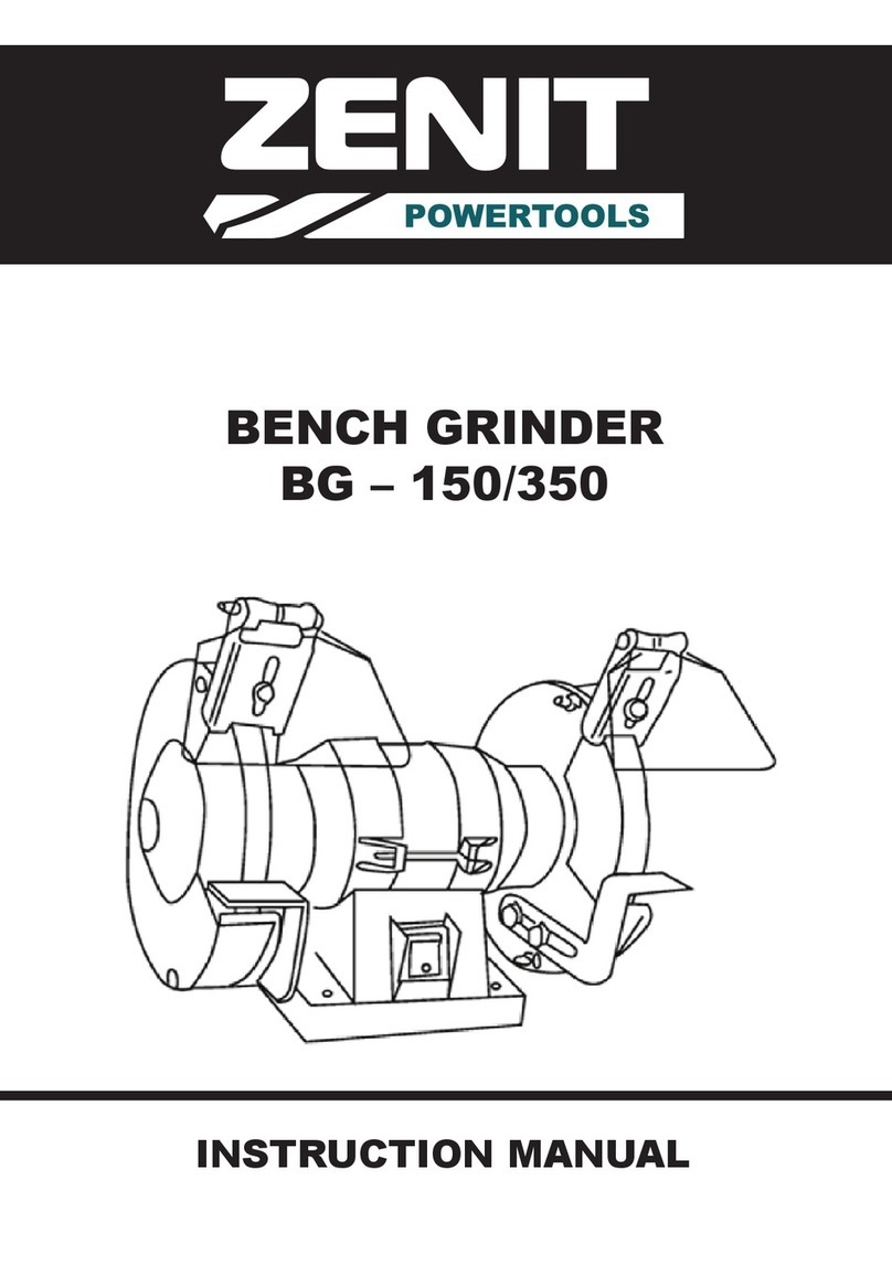
SMERIGLIATRICI E PULITRICI E
GRINDERS AND POLISHING MACHINES
SCHLEIFMASCHINEN UND POLIERMASCHINEN
TOURETS ET EBARBEUSES
ESMERILLADORAS Y LIMPIADORAS
ESMERILADORAS E MAQUINAS DE POLIR
www.femi.it

DICHIARAZIONE DI CONFORMITÁ CE DEL COSTRUTTORE
FEMI S.p.A.
Via del Lavoro, 4 - 40023 Castel Guelfo (BO) - ITALIA
Tel. +39-0542-670160 - Fax +39-0542-670185
Dichiara che la: SMERIGLIATRICE
è conforme alle disposizioni contenute nelle Direttive:
CEE 98/37 - 89/336 - 73/23
COMPLIANCE DECLARATION CE OF THE BUILDER
FEMI S.p.A.
Via del Lavoro, 4 - 40023 Castel Guelfo (BO) - ITALIA
Tel. +39-0542-670160 - Fax +39-0542-670185
Declare the: BENCH GRINDER
is in compliance with the rules contents in the Directives:
EEC 98/37 - 89/336 - 73/23
CE KONFORMITATS ERKLARUNG DES HERSTELLER
FEMI S.p.A.
Via del Lavoro, 4 - 40023 Castel Guelfo (BO) - ITALIA
Tel. +39-0542-670160 - Fax +39-0542-670185
Erklart dass: SCHLEIFMASCHINE
ist konform mit der Direktiven:
EWG 98/37 - 89/336 - 73/23
DECLARATION DE CONFORMITE CE DU CONSTRUCTEUR
FEMI S.p.A.
Via del Lavoro, 4 - 40023 Castel Guelfo (BO) - ITALIA
Tel. +39-0542-670160 - Fax +39-0542-670185
Declare que la: TOURET A MEULER
est conforme aux disposition contenues dans les Directives:
CEE 98/37 - 89/336 - 73/23
DECLARATION DE CONFORMIDAD CE DEL CONSTRUCTOR
FEMI S.p.A.
Via del Lavoro, 4 - 40023 Castel Guelfo (BO) - ITALIA
Tel. +39-0542-670160 - Fax +39-0542-670185
Declara que la: SMERILLADORA
esta conforme a las disposiciones contenide en la Directivas:
CEE 98/37 - 89/336 - 73/23
DECLARAÇÃO DE CONFORMIDADE CE DO CONSTRUTTORE
FEMI S.p.A.
Via del Lavoro, 4 - 40023 Castel Guelfo (BO) - ITALIA
Tel. +39-0542-670160 - Fax +39-0542-670185
Declara que a: ESMERILADORA DE BANCADA
suivindo as regras exigidas no contendo da Directivas:
CEE 98/37 - 89/336 - 73/23
01 07
02 08
03 09
04 10
05 11
06 12
2007 2010
2008 2011
2009 2012
404
405
424
425
1

EN
8
1 INTRODUCTION
Please read these instructions carefully in order to
learn how to use this machine and how to deal
with any contraindications. Keep these instructions
in a safe place: they are an integrating part of the
machine. This instruction manual is an integral part
of the machine and therefore must be kept complete
and handled with care. Always refer to the
contents reported in this manual for carrying out all
the operations required for using the machine to
the best advantage and under utmost safety
conditions.
Use the machine solely and exclusively for the uses
outlined below, as recommended in this manual,
and do not attempt to tamper with it, force it or use
it for other purposes.
1.1 CONVENTIONAL SYMBOLS
Never underestimate the warnings "ATTENTION -
CAUTION" given in this manual.
In order to draw the user's attention and to preserve
safety, hazardous operation are preceded by
symbols and notes that point out the danger and
explain how to behave to avoid any risk.
These symbols and notes are divided in three
categories, identified by the following words:
WARNING: dangerous-behaviours that
could cause serious injuries.
CAUTION: behaviours that could cause
slight injuries or damages to things.
NOTE: the notes preceded by this symbols
are technical and are aimed at making
operations easier.
1.2 STANDARDS ON SAFETY
The machine has been designed and manufactured
conforming to the norms set forth by the following
prevailing Machinery Directives: EEC 98/37 - EEC
73/23 - EEC 89/336
The annexed CE Declaration of Conformity, together
with the CE mark attached to the product, constitute
an essential element and are an integral part of the
machine: they guarantee that the product duly
conforms to the aforesaid safety Directives.
1.3 TYPE OF USE
This machine has been conceived and
manufactured to remove material, such as tool
grindings or lappings, from any type of metal.
In the bench grinder and polishing machine
(combined version) the shaft is fitted with an
extension on one or both sides, where it is possible
to fit several types of brushes (such as with steel
wires, with abrasive blades or in fabric) suitable
for any type of metal. Avoid using it for any other
type of use that is not foreseen by these
instructions.
1.4 SAFETY REGULATIONS
- Do not use the machine outdoors, in humid places
or in the presence of gas or flammable liquids.
- Put the machine in a well lit working area: this is
extremely important in preventing work
accidents.
- Do not force the machine unnecessarily:
excessive pressure could cause the grinding
wheel to deteriorate very quickly, the machine’s
performances could worsen and the motor be
damaged by overheating.
- Each time a machine operation is finished, turn
off the machine switching it to position “O”.
- Avoid wearing loose-sleeved work clothes or
accessories such as scarves, neck-chains or
bracelets which could be hooked by the moving
parts.
- Always use protection devices: accident
prevention eyeglasses as foreseen by
regulations, headsets or earphones and if
necessary, caps to hold back loose hair.
- Do not use the electric feeding cable to lift the
machine or to take off the plug from the current
tap. Avoid contact with sharp edges, oils and
high temperatures.
1 INTRODUCTION TO USE ..................................... 10
2 INSTALLATION ....................................................... 11
3 ADJUSTMENT ........................................................ 12
4 MAINTENANCE ...................................................... 14
INDEX

EN
9
1.5 DESCRIPTION OF THE MACHINE
-(Picture 1a: bench grinder)
-(Picture 1b: combined bench grinder)
1. MACHINE BODY
2. TURNING-ON SWITCH
3. ABRASIVE GRINDING WHEEL
4. TRANSPARENT SPARK ARRESTERS
5. SAFETY CAP
6. PIECE-REST
7. ADJUSTABLE CHIP GUARDS
8. KEEPER HOLES
9. BRUSH PROTECTION
10 . SHAFT EXTENSION
1.6 PACKING REMOVAL, STORAGE and
TRANSPORT
Packing removal
If the machine is fit with a base, first separate it
from the machine by removing the fastening screw
nuts.
Remove the machine from the packing that protects
it during transport. Please do not throw the box
away, it could be useful in case you will have to
displace the machine or need to store it for long
periods.
Displacement and transport
WARNING: The machines with more
than 1100 Watt are very heavy and must
therefore be lifted and positioned on
the choosen working place.
Otherwise they have to be displaced
by at least two people.
Machines with a lower power can be lifted and
displaced by one person only.
Storage
Should you have to store the machine, please take
into account the ideograms printed on the box. Do
not crush the box with overloads and put it in a
safe position so that it does not fall.
2 INSTALLATION
Positioning in working area (Picture 2)
CAUTION: Ensure that the machine is
located in a suitable area both as far
as work environment and lighting are
concerned: always keep in mind that
the overall work environment
conditions are essential for preventing
accidents.
Position the machine on a sufficiently flat bench
so as to have the best stability possible.
The ideal height of the bench is that allowing the
positioning of the piece-rest 6 at about one meter
from the ground.
Machine fastening on working table (Picture
1a)
We recommend to secure the machine to the work
bench, by inserting four M6 screws in holes 8,
locking them on the opposite side using the
appropriate screw nuts.
Machine fastening on the column (where
foreseen)
In order to secure the machine to the base, use
the standard fittings provided. Match holes 8of
the machine with the corresponding holes in the
upper support surface of the base.
Securing the base to the floor
The column (if delivered with the machine) has to
be fixed to the floor through the special holes on
its lower part. Furthermore fill it with sand to avoid
vibrations and in order to increase its stability.
Fitting of auxiliary equipment
From the bag inside the packaging take out the
adjustable chip guards 7, the transparent spark
arresters 4and the piece-rests 6 and assemble
them onto the safety caps 5using the screws
inside the same bag, as shown in picture.

EN
10
2.1 ELECTRIC CONNECTION
Grounding
Check that the power grid to which the machine is
plugged in is grounded as foreseen by the safety
rules in force, and that the current socket is in
good condition.
Plug fitting
Connect a plug in compliance with safety regulation
to the end of the mains cable of the machine, check
that the yellow/green protective conductor is fitted
into the relative terminal.
Choice of the thermal protection
We remind the user that a magnetothermic
protection, fit for safeguarding all the conductors
from short-circuits and overloads, must always
be placed before the power grid.
Said protection is to be chosen according to the
electric specifications of the machine, indicated
on the data plate applied to it.
2.2 NOISE RELATED INFORMATION
Under normal working conditions as described in
these instructions, the grinding machines bring
about a level of acoustic pressure corresponding
to:
Leq = 60 dB (A) when idling;
Leq = 77 dB (A) during workings (for example:
lapping a C 40 steel rod)
Tests were carried out according to UNI 7712,
ISO 3740, ISO 3746 and CEE 89/392 regulation.
It is however recommended to use personal means
for hearing protection, such as headsets or
earphones.
2.3 ELECTROMAGNETIC COMPATIBILITY
INFORMATION
The recent European Safety Standards, especially
EEC Directive 89/336, set forth that all the
equipment must be fit with radio interference
suppressors both to and from the outside
environment.
This machine conforms to such Standards.
Tests were carried out according to EN 55011, EN
55014, EN 50082-1, IEC 1000-4-2, IEC 1000-4-4
regulations.
3 ADJUSTMENTS (Picture 2-3)
The international safety rules prescribe that the
adjustable chip guards 7 and the piece-rest 6 are
to be positioned not more than 2 mm. from the
peripheral edge of the grinding wheel.
As the grinding wheel wears out, its diameter
decreases, and these distances are then
increased.
Periodically check their values and, if they have
increased, reduce them within the fixed limits by
adjusting accessories 7 and 6 by means of their
fastening screws.
3.1 USE OF THE GRINDING WHEEL (Picture
4-8)
Insert the input cable plug into the current socket
of the power grid.
Start running the machine by pressing the green
pushbutton 12 of switch 2.
WARNING: ALWAYS WEAR ACCIDENT
PREVENTION EYEGLASSES.
Gently bring the piece to be worked in contact
with the grinding wheel, laying it on piece-rest 6,
and start applying pressure progressively, but
without pushing too hard, so that the machine will
not lose the normal r.p.m.
CAUTION: The piece being worked on
must always be held with both hands,
and cooled every now in a tank of
water.
The grinding wheel on the right is of a thicker grain:
it is more suitable for chipping operations.
The left grinding wheel is of a thinner grain, and is
more suitable for finishing and grinding tools.
In order to stop the machine, press the red
pushbutton 13 of switch 2or press the emergency
stop button 11.

EN
11
3.2 REPLACING THE GRINDING WHEEL
(pictures 2-5-6)
WARNING: Prior to performing any
maintenance operation, disconnect the
electric power supply.
Activate switch 2to stop the machine and wait
until the grinding wheels have stopped completely.
Take away parts 7and 6.
Remove cover 14 from the safety cap, unscrewing
the relevant screws.
With an open key unscrew the nut 15 and keep the
shaft steady through an hexagonal key, keeping in
mind that on the left side it has a left-handed
threading, and therefore it is unscrewed in
clockwise direction.
Replace worn out grinding wheel with a new one.
Check if a new grinding wheel is integral
Before mounting the new grinding wheel, it is
advisable to perform a sound test in order to check
its integrity.
To carry out this test, the grinding wheels must be
dry and clean, otherwise the emitted sound could
result dampened. With the help of a non-metallic
tool (wooden handle of a screwdriver or a wooden
mallet), lightly strike the grinding wheel on its side
(picture 5): a light strike against an integral grinding
wheel produces a pleasant and clear sound.
If, on the other hand, the emitted sound is dull or
cracked, the grinding wheel should not be used.
Retighten 15 screw nut.
Reassemble cover 14 of the safety cap.
Re-assemble the pieces that were taken off
previously.
If the radial and axial movement of the rotating
grinding wheel, gauged both on the circumference
and on the side wall of the grinding wheel
respectively, should be too much, the grinding wheel
produces excessive vibration when used at
maximum rotating capacity.
In order to decrease such value, stop the machine,
loosen the grinding wheel and turn it on its axis by
1/4 turn holding the motor shaft firmly, then lock the
grinding wheel. If the problem persists, repeat the
operation as many times as required until the best
possible position is found.
3.3 USE OF THE BRUSH (Fig. 7)
The right-hand part of the combined bench grinder
is manufactured so that it can house a brush for
the cleaning or polishing of various types of metals.
It is possible to fit metal wire brushes (cleaning) or
cloth/fabric brushes (polishing) with varying
maximum diameter, maximum width and stop collar
hole, depending on the model (refer to the “USE OF
APPROPRIATE TOOLINGS” table).
Ensure that the diameter of the middle collar 16 that
keeps the wires together is always greater than
the diameter of the fastening flanges 17 provided
on the machine.
WARNING: It is prohibited to secure the
brushes with the flanges in direct
contact with the wires.
Every now and then check the general condition of
the brush by visually inspecting it, especially as
concerns the hold of the wires, by means of the
middle collar. If you notice that the collar does not
close perfectly any more, replace the brush with a
new one at once.
WARNING: Prior to performing any
maintenance operation, disconnect the
electric power supply.
Fitting of the brush
Ensure that the machine is OFF and that the toolings
provided (e.g. grinding wheels) are perfectly still.
Use an Allen wrench to unscrew the screw nut 18
that locks the flanges to the shaft.
Remove the tightening flange 17 from its seat.
Fit the brush onto the shaft, ensuring that the hole
of the brush has the same diameter of the shaft or
of the adapting bush provided onto which it is
secured.
Re-position the tightening flange 17 onto the shaft
making it touch the collar 16 of the brush.
Remove the middle side plug 19 from the protection
and introduce a socket wrench through the hole
until the seat is properly fit on the shaft 20.
At this point, keeping the shaft locked by means of
the socket wrench, tighten the fastening screw
nut on the flanges.
Try to turn the brush by hand to make sure that it is
centered. If it does not turn properly, repeat the
aforesaid steps.

EN
12
mm
/
150x25x16
/
150x25x16
ITEM
404
424
405
425
mm.
150x20x16
150x20x16
200x20x16
200x20x16
USE OF APPROPRIATE TOOLINGS
3.4 SUCTION AND POWDERS COLLECTION
The machine is fitted with holes for discharging
the powders both from the wheels protection
caps (bench-grinders) and from the brush
protection (combined versions and polishing
machines).
It is possible to fit it with a powders suction system.
Ask your dealer the complete suction unit with all
connections and the bags for powders collection
in order to keep the working area clean and
salubrious.
4 MAINTENANCE
Normal operations of routine maintenance, which
can be also be carried out by non-skilled
personnel, are all described in the previous
paragraphs and in the present one.
In case the intervention of qualified personnel is
required for extraordinary maintenance operations,
or in case of repairs, both during guarantee periods
and afterwards, always turn to an authorized
service center, or directly to the factory if the
service center is not present in your area.
4.1 DISPOSAL OF THE MACHINE, PACKING
At the end of the machine life, if
the machine must be scraped,
contact an authorised waste
disposal centre in order to comply
with the Standards for hygiene
and environment safeguard.
The packing must be disposed
of according to the ruling
standards by delivering it to authorised people for
the collection, disposal or reclaim.
Please contact the ASSOCIATION OF USED OILS
near to you.
2002/96/EC
This manual suits for next models
3
Table of contents
Other Femi Grinder manuals
Popular Grinder manuals by other brands
Cibo
Cibo original Finit-Easy manual
Berner
Berner 061355 user manual

Ozito
Ozito DAL-230 quick start guide
Universal Tool
Universal Tool UT8727-1 General Safety Information & Replacement Parts

Meister
Meister MWS2400-230 Translation of the original instructions

Superabrasive
Superabrasive LAVINA 30G-FX user manual


