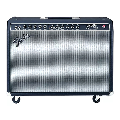
CIRCUIT DESCRIPTION
PRE-AMPLIFIER
The guitar signal is input to J1 for high gain and J2
for lower gain. When both inputs are used, both
signals receive low gain. V1-A and V1-B provide
two gain stages while R6 provides clean volume
control. The tone stack, composed of R13,14,15
and associated components provide treble, bass
and middle tone control respectively. V2-A provides
gain lost in the tone stack. When the channel select
switch is depressed, relays K1 and K2 are
energized. This has the effect of disconnecting the
volume control, thereby increasing the gain of the
first stage while removing the short across R7, drive
control, allowing it to control the amount that V2-A
is overdriven. R26 is now in the circuit and is used
to control the volume of the overdriven signal. The
clean or distorted signals are input to opamp U1-A,
employed as a unity gain buffer to develop the
PREAMP out signal at J3. Opamps U2-A and U2-B
function as reverb tank drive and recovery
respectively. When an external signal is plugged
into J4, POWER AMP IN, the internal pre-amp
signal is diverted from the power amp and the
external signal instead is fed to the reverb drive and
the power amp.
POWER AMPLIFIER
R40 and R38 sum the signals from the preamp and
the reverb tank and feed them into the power
amplifier. V3-A and V3-B serve as phase splitters
which produce two out of phase signals for the
purpose of driving V4 and V5 which act as a push-
pull pair in a class A-B power amplifier. T1 matches
the 6L6 plate impedance to the speaker load.
POWER SUPPLY
The line voltage is fed to T2’s primary through the
line fuse, F1, and the inrush current limiter, RT1.
The input voltage is then stepped up or down as
needed, rectified and filtered to produce the high X,
Y, Z and B+ voltage for the tubes as well as the +/-
16V rails for the opamps. A 6.3VAC secondary
powers the power indicator lamp and the tubes’
heaters.
FOOTSWITCH INTERFACE
A two button footswitch (P/N 0994056000) is
included for remote switching of the channels and
reverb. When the VAC signal is clamped by either
the internal (S2) or external (footswitch) diodes, a
positive or a negative level that is being compared
to a reference by comparators U3-A/B is changed,
causing the comparator outputs to change state.
U3-b senses the positive level change and
energizes K1 and K2. U3-A senses the negative
level change and turns on Q2 which mutes the
reverb. U4-A and associated circuitry act as a zero
crossing detector which mutes the preamp during
channel changes.
.


