Ferguson FL32WX2 User manual

FERGUSON LCD MONITOR
MODEL – FL32WX2
PAL TV SYSTEM
USER MANUAL
EARPHONE MENU VOL POWER
INPUT
CF
SD/MMCSMMS


iii
Preface
About this manual
Thank you for purchasing the FERGUSON 32-inch LCD Colour Television! We are pleased to present a product that has been
designed with excellent quality, reliability, and performance to make your viewing experience even more satisfying than before.
This manual provides detailed descriptions on how to use this product, and adjust the picture and colour quality to according to
your personal preferences.
Copyright information
Information in this document has been carefully checked for accuracy; however, it is subject to change without notice. This
document contains proprietary information protected by copyright. All rights are reserved. No part of this publication may be
reproduced, transmitted, transcribed, stored in a retrieval system or translated into any language or computer language, in any
form or by any means, electronic, mechanical, magnetic, optical, chemical, manual or otherwise, without the prior written
permission of this company.
Copyright© 2004, All Rights Reserved.
Trademarks
Ferguson, the company logo, and the trademark are the registered trademarks of Ferguson Electric and Machinery Co., Ltd. and
its affiliates in the United States and other countries.
VGA and XGA are registered trademarks of International Business Machines Co., Inc.
All other trademarks are the property of their respective owners.
Disclaimer
Ferguson makes no representations or warranties, either expressed or implied, with respect to the contents hereof and
specifically disclaims any warranties, merchant ability or fitness for any particular purpose. Further, Ferguson reserves the right
to revise this publication and to make changes from time to time in the contents hereof without obligation of this company to
notify any person of such revision or changes.

iv
Important safety information
Damage
Never use your TV if it is damaged in any way. Always place your TV on a flat level surface avoiding anywhere which may be
subject to strong vibration.
Weather
It is advisable to unplug the aerial during an electrical storm.
Moisture
Do not allow your TV to be exposed to rain, moisture, dust. If any liquid is spilt into your TV it can cause serious damage. If you
spill any liquid into your TV switch it off at the mains immediately. Contact your store.
Interference
Do not place your TV on or near appliances which may cause electromagnetic interference (TV or Hi-Fi speakers). If you do, it
may adversely affect the working of the unit, and cause a distorted picture or sound.
Temperature
Avoid extremes of temperature, either hot or cold, place your TV well away from heat sources such as radiators or gas/electric
fires.
Ventilation
The TV must be well ventilated. Do not cover your TV or position in a small confined space. It is recommended that you leave a
10cm gap all around your TV.
Batteries
Batteries are easily swallowed by young children. Do not allow young children to play with the remote control unit.
Covers
Do not remove any fixed covers as this may expose dangerous voltages.
Standby
Do not leave your TV in standby for long periods of time e.g. overnight or while on holiday.
Screen Burn
ATTENTION! Please note that some programmes are broadcast with a logo that will appear in the corner of your TV screen.
Some of these logo's can be very bright and may cause damage by permanently marking the logo on the screen. To prevent this,
avoid leaving channels displaying a logo for prolonged periods of time, particularly when the TV is not being watched.
CAUTION
RISK OF ELECTRIC
SHOCK; DO NOT OPEN
CAUTION:
TO REDUCE THE RISK OF ELECTRIC SHOCK, DO NOT
REMOVE COVER. NO USER-SERVICEABLE PARTS INSIDE.
REFER SERVICING TO QUALIFIED SERVICE PERSONNEL.
WARNING
This symbol is intended to tell the user
that parts inside the product pose a
risk of electric shock to persons.
CAUTION
This symbol is intended to tell the user
that important operating and servicing
instructions are described here.

Table of Contents
v
Overview of the LCD TV. . . . . . . . . . . . . 1
Features .................................................................. 1
Unpacking.............................................................. 2
Product components............................................. 3
Front view...................................................... 3
Rear view....................................................... 4
Remote control.............................................. 5
Getting started. . . . . . . . . . . . . . . . . . . . . . 8
Inserting the remote control batteries................ 8
Connecting power................................................. 9
Basic connections .................................................. 9
ANT port...................................................... 11
Component IN port.................................... 11
SCART ports................................................ 12
S-IN port ...................................................... 12
AV IN port................................................... 13
AV OUT port............................................... 13
PC IN port.................................................... 14
Inserting memory flash cards............................ 15
Using the LCD TV . . . . . . . . . . . . . . . . . 16
Watching the LCD TV........................................ 16
Selecting the video inputs......................... 16
Sorting and naming channels................... 16
Selecting a channel..................................... 17
Changing the volume ................................ 18
Additional audio settings.......................... 19
Selecting stereo or bilingual
programmes....................................... 19
Using surround sound mode .......... 19
Using audio mode............................. 19
Using auto volume level .................. 19
Additional video settings ......................... 20
Using the display button.................. 20
Selecting a video mode..................... 20
Using video mute.............................. 20
Changing the screen mode .............. 20
Using PIP (Picture in Picture)
and POP (Picture on Picture)................... 21
Setting the TV off timer............................. 22
Using the teletext function ....................... 22
Using the TV as a monitor ................................ 23
Using the card reader function......................... 23
Using the OSD menus. . . . . . . . . . . . . . . 24
Changing picture settings ................................ 25
Changing audio settings ................................... 26
Changing system settings ................................. 27
Changing PIP settings ....................................... 28
Changing TV settings ........................................ 29
Changing colour settings .................................. 31
Specifications . . . . . . . . . . . . . . . . . . . . . . 32
Troubleshooting. . . . . . . . . . . . . . . . . . . . 33


1
Overview of the LCD TV
Congratulations on purchasing the FERGUSON 32-inch LCD Colour Television. This product has been
designed to provide you with a rich audio and video experience, along with ease of use and convenient
connections. This monitor enables you to watch broadcast or cable television channels, connect a VCR,
VCD or DVD player to watch your favourite movies, or connect a computer to use the display as a
monitor. The TV is equipped with convenient control buttons located on the front panel and a handy
remote control to let you adjust the TV settings and customize the TV preferences through an easy-to-use
on-screen menu system.
Features
Enjoy the versatility of your LCD TV with its wide variety of features:
• 32-inch colour active matrix TFT LCD TV with remote control
• Safe, sturdy construction
• High contrast - 500:1 (typical), and brightness - 470 cd/m2
• Fast response time - 18 ms (Tr), 15 ms (Tf)
• Maximum display resolution: 1280 x 768
• Picture-in-picture (PIP) and picture-on-picture (POP) support
• Built-in TV tuner with 128 channels
• Audio/video support:
— Component (YCbCr/YPrPb) video input
— S-Video input
— Two SCART audio/video inputs
— VGA input
— Composite video input
— Composite audio/video output
— Multiple stereo audio inputs corresponding to each video input
— 3.5 mm stereo head phone output
— 3.5 mm audio line-in input
• Card reader support for Memory Stick™ (MS), SmartMedia™ (SM), Secure Digital™ (SD),
MultiMediaCard™ (MMC), and CompactFlash™ (CF) memory cards.
• On-Screen Display (OSD) menu system
• Built-in 12W x 2 speakers
2
Unpacking
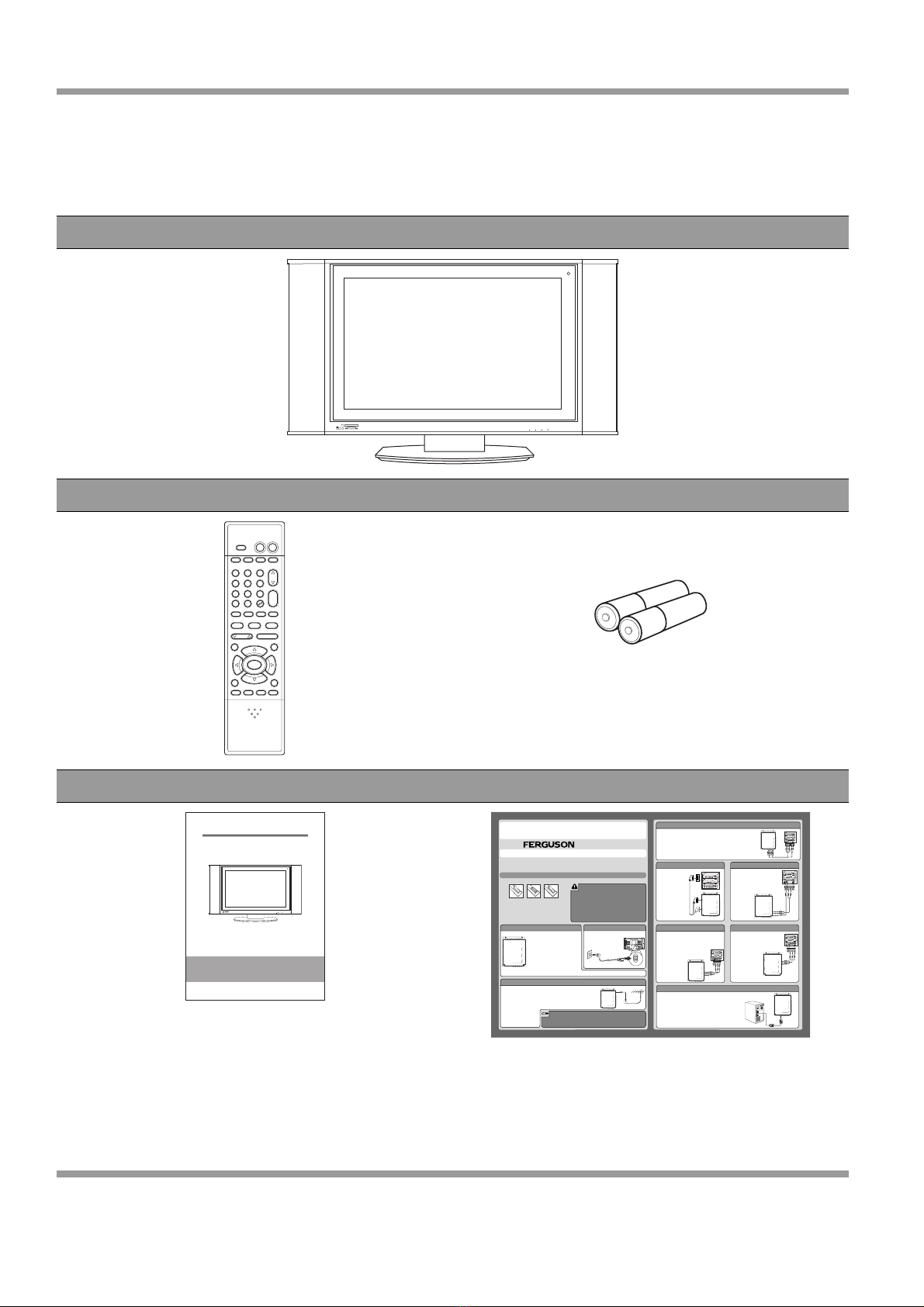
When you unpack this LCD TV, make sure the box contains the following items:
If any of these items appears to be missing or damaged, please contact your vendor or authorised service
personnel for assistance.
FERGUSON 32-inch LCD Colour Television
Remote control 2 AAA batteries
User manual Quick Start guide
EARPHONE MENU VOL POWER
INPUT
CF
SD/MMCSMMS
SCART
SOUND
VIDEO MUTESURROUND
TELETEXT SUB PAGE INDEX
VOL
TV/AV/S
MUTE POWER
VIDEO
MODE
AUDIO
MODE
0FF
TIMER
DISPLAY
CH
1 2 3
4 5 6
7 8 9
0
MENU
PAGE ZOOM HOLD
COMPONENT
PC WIDE
+
-
- --
/
AI AUDIO
FERGUSON
FERGUSON LCD MONITOR
FERGUSON LCD MONITOR
MODEL
MODEL
–FL32WX2
FL32WX2
PAL TV SYSTEM
PAL TV SYSTEM
USER MANUAL
USER MANUAL
EAR MENU VOL CH POWER
TV/AV/PC
CF
SD/MMCSMMS
Quick Start Guide
Quick Start Guide
Getting started
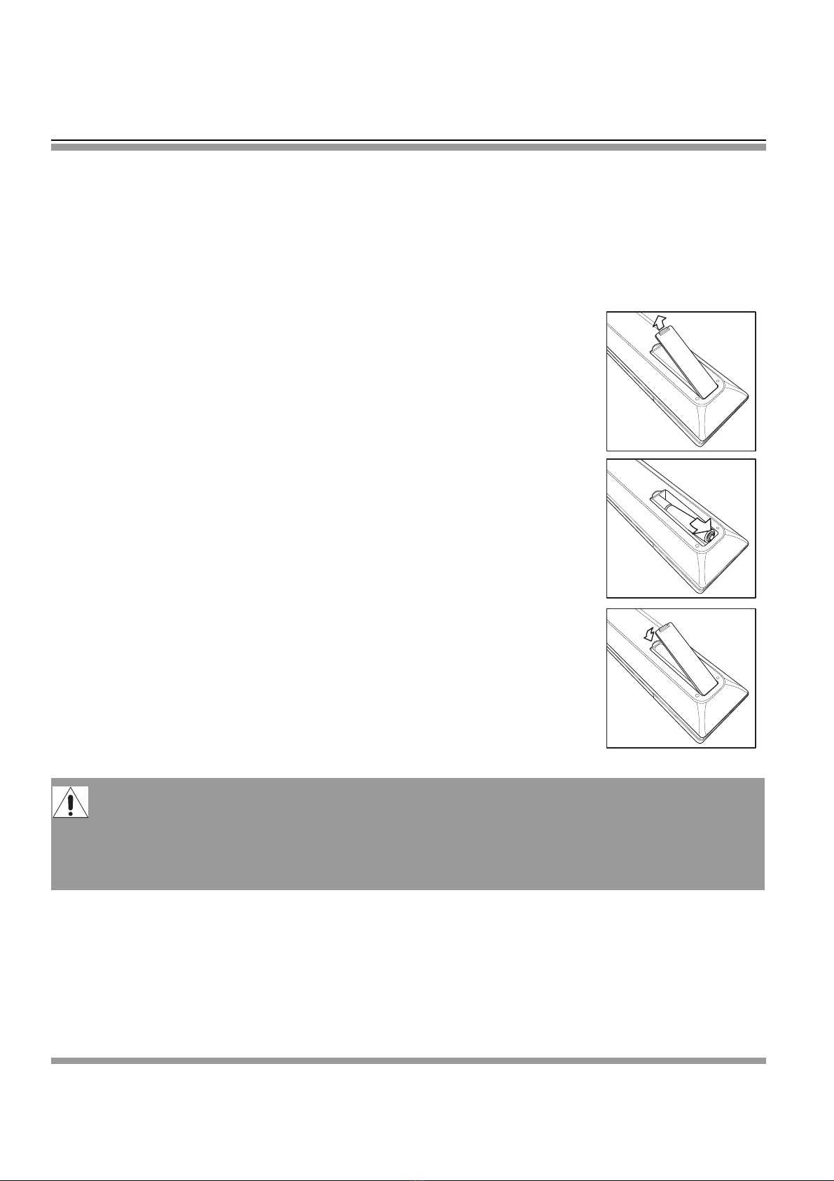
Inserting the remote control batteries
Insert the two AAA batteries provided into the remote control as described below:
ANT
R
RLY
Pb/Cb
Pr/Cr
PC/IN
PCAUDIOIN
SCART2-IN
SCART1-IN
DVI
L
R
L
R
L
S-VIDEO
VIDEO
VIDEO
S-IN
AV-IN
AV-OUT
COMPONENTIN
ANT
R
RLY
Pb/Cb
Pr/Cr
PC/IN
PCAUDIOIN
SCART2-IN
SCART1-IN
DVI
L
R
L
R
L
S-VIDEO
VIDEO
VIDEO
S-IN
AV-IN
AV-OUT
COMPONENTIN
Connecting power
ANT port
Basic connections
The ANT jack is provided to directly connect cable TV, satellite or an antenna as follows:
Please refer to the following sections for detailed instructions about connecting the audio/video (AV)
device of your choice to your LCD TV and view your favorite programs or movies. These sections
describe the basic procedures required to set up your TV for easy and convenient viewing.
1.Pull the latch on the battery compartment cover on the
rear of the remote control and remove the cover.
2.Insert the two supplied AAA batteries. Check the +
and - ends of the batteries before inserting them in the
compartment. remote control and remove the cover.
3.Replace the cover and make sure it snaps securely
back into place.
ΘDo not mix old and new batteries or batteries of
different types together.
ΘDo not short circuit, disassemble, heat or fire
batteries.
ΘRemove the batteries to avoid damage from
possible battery leakage if you anticipate that the
remote control will not be used for an extended
period of time.
ΘPlease handle the remote control with care. Avoid
dropping it, getting it wet, or placing it in direct
sunlight, near a heater or in an area of high humidity.
1. Connect the supplied power cord to the AC IN
jack on the rear of your TV.
2. Connect the other end of
the power cord to a power
outlet.
ANT
R
RLY
Pb/Cb
Pr/Cr
PC/IN
PCAUDIOIN
SCART2-IN
SCART1-IN
DVI
L
R
L
R
L
S-VIDEO
VIDEO
VIDEO
S-IN
AV-IN
AV-OUT
COMPONENTIN
1 2 3
The TECO 32-inch LCD Colour Television
provides multiple input and output ports to
enable you to connect different types of
A/V devices such as an antenna or CATV
line, a VCR/VCD/DVD player, a satellite
receiver, or even a PC.
You can also use the LCD TV as a flash
memory card reader and view your digital
photographs or video clips directly on the
TV without requiring a PC connection.
The back panel of the LCD TV provides
input and output jacks to make these
connections possible. The following
sections discuss the various ports and the types of A/V devices that can be connected to your TV.
1.Connect one end of a CATV 75. coaxial cable to the ANT jack on the
rear panel of the TV.
2.Connect the other end of this cable to CATV wall mounting as shown
below on the left. You may also need to use a cable adapter to connect
to your CATV wall mounting, depending on your installation.
If you have subscribed to a
cable TV system using
scrambled or encoded signals
requiring a cable box to view
all channels, connect the the
ANT jack to the cable box's
ANTENNA OUT jack.
It is strongly recommended that you connect the antenna using a 75W coaxial
cable to get optimum picture and sound quality. A 300W twin lead cable can be
easily affected by radio and other background noise, resulting in signal
deterioration. When using a 300W twin lead cable, please keep this cable as far
away from the TV as possible.
Component IN port
The COMPONENT IN port lets you connect your TV to high quality video
equipment such as a DVD player, digital TV receiver, or digital satellite
receiver. This port consists of component audio (L, R) and video (YCbCr or
YPbPr) connectors and provides the highest picture quality. To connect your
A/V device to this port, do the following:
1.Using a component video cable, connect the video (YCbCr/YPbPr) jacks on
the TV to the corresponding video output jacks of your A/V device.
2.Using an audio cable, connect the audio (L, R) jacks on the TV to the
corresponding audio output jacks of your A/V device.
ANT
R
RLY
Pb/Cb
Pr/Cr
PC/IN
PCAUDIOIN
SCART2-IN
SCART1-IN
DVI
L
R
L
R
L
S-VIDEO
VIDEO
VIDEO
S-IN
AV-IN
AV-OUT
COMPONENTIN
YLRCbCr
Video Audio
SCART ports
ANT
R
RLY
Pb/Cb
Pr/Cr
PC/IN
PCAUDIOIN
SCART2-IN
SCART1-IN
DVI
L
R
L
R
L
S-VIDEO
VIDEO
VIDEO
S-IN
AV-IN
AV-OUT
COMPONENTIN
or
The LCD TV has two
SCART (SCART1,
SCART2) ports for
connecting up to two
SCART A/V devices
with the LCD TV.
To connect an A/V
device to the SCART
port, use a SCART
cable to connect the
device to either one
of the SCART ports
on the rear panel of
the LCD TV.
AV IN port AV out port
PC IN port
1.Using an S-Video cable, connect
the video (S-Video) jack on the TV
to the corresponding S-Video
output jack of your A/V device.
2.Using an audio cable, connect the
audio (L, R) jacks on the TV to the
corresponding audio output jacks
of your A/V
device.
S-IN port
ANT
R
RLY
Pb/Cb
Pr/Cr
PC/IN
PCAUDIOIN
SCART2-IN
SCART1-IN
DVI
L
R
L
R
L
S-VIDEO
VIDEO
VIDEO
S-IN
AV-IN
AV-OUT
COMPONENTIN
AV-OUT
S-VIDEO
RL
VIDEO
1.Using a composite video cable, connect the video
(VIDEO) jack on the TV to the video
output jack of your A/V device.
2.Using an audio cable,
connect the audio
(L, R) jacks on the TV
to the corresponding
audio output jacks of
your A/V device.
The AV IN port supports composite video and
provides good quality video. To connect an A/V
device such as a VCR, VCD player, or
DVD player, do the following:
AV-OUT
RL
VIDEO
ANT
R
RLY
Pb/Cb
Pr/Cr
PC/IN
PCAUDIOIN
SCART2-IN
SCART1-IN
DVI
L
R
L
R
L
S-VIDEO
VIDEO
VIDEO
S-IN
AV-IN
AV-OUT
COMPONENTIN
AV-OUT
RL
VIDEO
ANT
R
RLY
Pb/Cb
Pr/Cr
PC/IN
PCAUDIOIN
SCART2-IN
SCART1-IN
DVI
L
R
L
R
L
S-VIDEO
VIDEO
VIDEO
S-IN
AV-IN
AV-OUT
COMPONENTIN
Use the AV OUT port to connect your
LCD TV to an A/V device such as a DVD
recorder, VCR, home theater audio
equipment, and so on, as follows:
1.Using a composite video cable, connect
the video (VIDEO) jack on the TV to the
video input jack of
your A/V device.
2.Using an audio cable,
connect the audio
(L, R) jacks on the TV
to the corresponding
audio input jacks of
your A/V device.
Connect your LCD TV to a PC or portable computer with the
PC IN port, to use the LCD TV as a monitor for your PC. To connect
to a PC, do the following:
1.Connect the video output of your PC or portable computer to
the PC IN (VGA) video input on the back panel of the TV using a
VGA cable.
2.Connect the Line out audio output of your PC to the
PC AUDIO IN jack of the TV.
ANT
R
RLY
Pb/Cb
Pr/Cr
PC/IN
PCAUDIOIN
SCART2-IN
SCART1-IN
DVI
L
R
L
R
L
S-VIDEO
VIDEO
VIDEO
S-IN
AV-IN
AV-OUT
COMPONENTIN
FL32WX2

3
Product components
The following section describes the various components of the LCD TV. Please take a few moments to
familiarize yourself with the product and its control panel before using it.
Front view
Component Function
1. Speakers Produces stereo sound.
2. Power button Turns power on or off.
3. / Increases or decreases channel numbers.
4. VOL –/+ Increases or decreases the volume.
5. MENU button Turns the On-screen Display (OSD) menu on or off.
6. INPUT button Switches the input source displayed on the screen between the ANT,
AV-IN, and PC-IN inputs.
7. EARPHONE Connects to external headphones.
8. SM card slot Insert an SM card in this slot.
9. SD/MMC, MS slot Insert an SD/MMC or MS card in this slot.
10. CF card slot Insert a CF card in this slot.
11. Power indicator LED Indicates if the power is turned on (green), off (unlit), or if the TV is in
stand-by mode (red).
EARPHONE MENU VOL CH POWER
INPUT
CF
SD/MMCSMMS
EARPHONE MENU VOL
3245678910
1
11
1
POWERINPUT
CF
SD/MMCSMMS
4
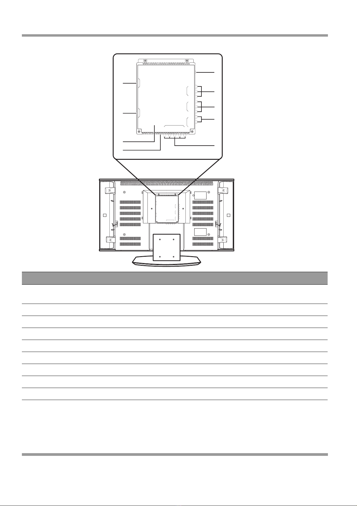
Rear view
Component Function
1. ANT input Connects to your VH/UHF antenna or coaxial cable a from local TV service
provider.
2. AV-OUT Connects to the audio and video input jacks of your A/V device.
3. AV-IN Connects to the audio and composite video output jacks of your A/V device.
4. S-IN Connects to the audio and S-Video output jacks of your A/V device.
5. COMPONENT IN Connects to the audio and component video output jacks of your A/V device.
6. PC IN Connects to the VGA output of your PC or portable computer.
7. PC AUDIO IN Connects to the audio output (earphone jack) of your PC or portable computer.
8. SCART2-IN Connects to the SCART output of your A/V device.
9. SCART1-IN Connects to the SCART output of your A/V device.
ANT
R
RLY
Pb/Cb
Pr/Cr
PC/IN
PCAUDIO IN
SCART2 -IN
SCART1 -IN
L
R
L
R
L
S-VIDEO
VIDEO
VIDEO
S-IN
AV-IN
AV-OUT
COMPONENT IN
ANT
R
RLY
Pb/Cb
Pr/Cr
PC/IN
PC AUDIO IN
SCART2 -IN
SCART1 -IN
L
R
L
R
L
S-VIDEO
VIDEO
VIDEO
S-IN
AV-IN
AV-OUT
COMPONENT IN
1
2
3
4
5
6
7
8
9

5
Remote control
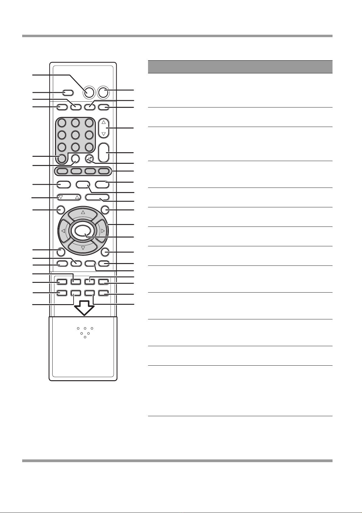
Component Function
1. POWER Turns power on or off.
2. DISPLAY Press repeatedly to display current
time, channel number, or video
input signal.
3. OFF TIMER Press repeatedly to set the off
timer to 10 through 90 minutes.
The TV enters stand-by mode after
the specified time interval.
4. /Decreases or increases the
channel number.
5. VOL –/+ Increases (+) or decreases (–) the
volume.
6. JUMP Switches to the previously viewed
channel.
7. TELETEXT HOT KEYS Select groups of pages in teletext
mode.
8. INDEX Displays a list and information
about the teletext pages.
9. SUB PAGE Displays the teletext as an overlay
over the programme you are
currently watching.
10. ZOOM/HOLD Zoom enlarges the teletext page;
Hold freezes the current teletext
page on the screen.
11. VIDEO MUTE Turns off the video display. The
TV screen turns blank.
12. ARROW KEYS Press the up, down, left, right
arrow keys to scroll through the
OSD menu options.
13. MENU Displays the OSD menu. Press
repeatedly to view the different
menu pages or exit the OSD
menu.
14. AI AUDIO Adjusts the audio volume
automatically according to the
audio level of the channel or video
programme.
SCART
SOUND
VIDEO MUTESURROUND
TELETEXT SUB PAGE INDEX
VOL
TV/AV/S
MUTE POWER
VIDEO
MODE
AUDIO
MODE
0FF
TIMER
DISPLAY
CH
1 2 3
4 5 6
7 8 9
0
MENU
PAGE ZOOM HOLD
COMPONENT
PC WIDE
+
-
- --
/
AI AUDIO
AUTO PLAY
PIP/POP
ROTATE
SUB SOURCE
CARD PLAY
POSITION
PREVIEW/FULL
SWAP
1
2
3
4
5
6
7
8
9
10
11
12
13
14
15
16
17
18
19
20
21
22
23
24
25
26
27
28
29
30
31
32
33
34
35
36
FERGUSON
6
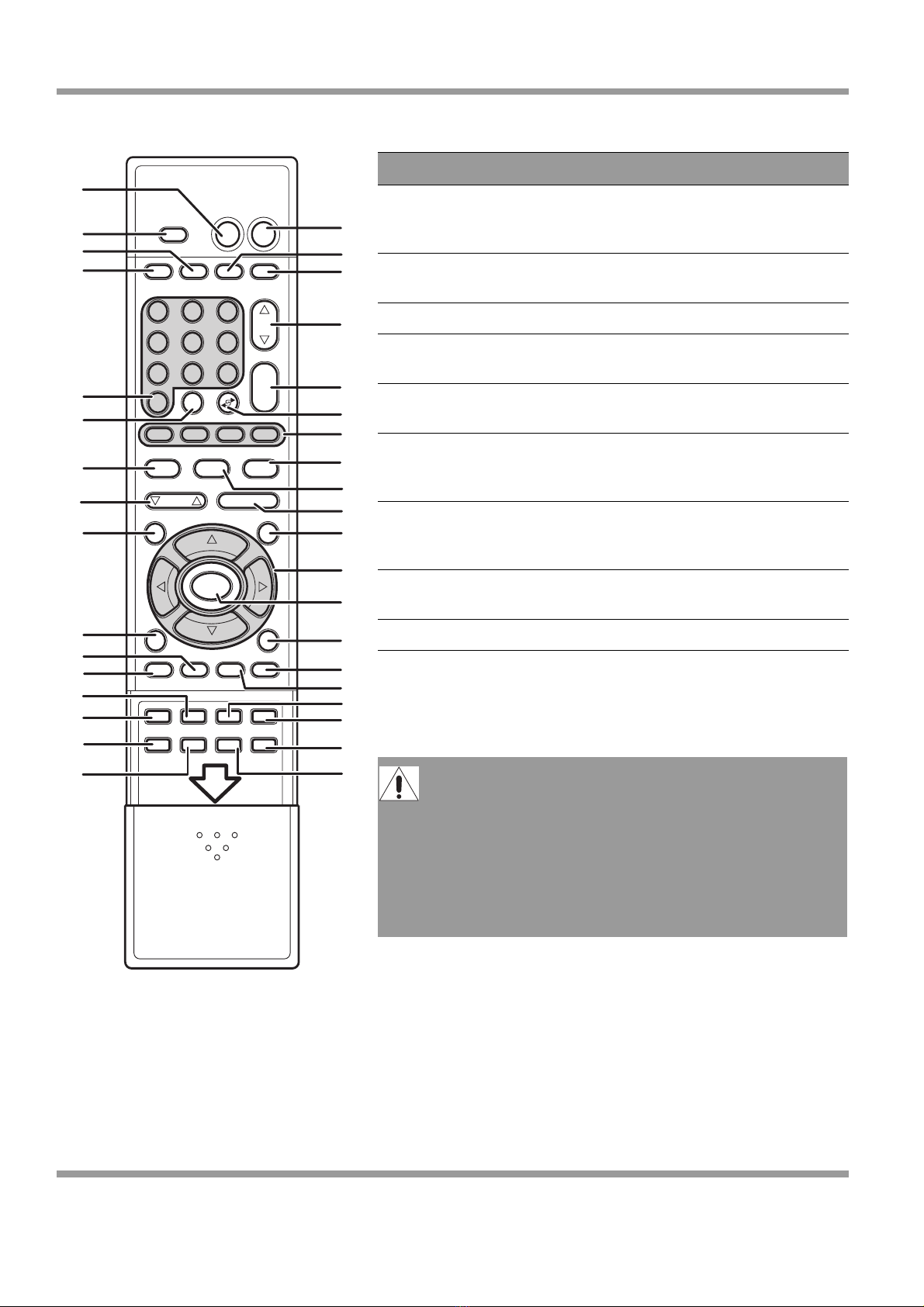
Component Function
15. WIDE Switches the display mode
between various wide modes.
(Mode 1, Mode 2, Mode 3, Mode 4,
4:3, FULL)
16. PC Selects the PC-IN input as the
video source signal.
17. PREVIEW/FULL Switches between thumbnail and
full screen mode when viewing
pictures from the flash memory
card.
18. CARD PLAY Starts playback of an audio or
video file from the flash memory
card.
19. POSITION Changes the PIP position (four
positions)
20. SWAP Toggles between the main screen
and the sub screen.
21. SUB SOURCE Selects the sub source for PIP and
POP modes.
22. PIP/POP Toggles between PIP and POP
modes.
23. ROTATE Rotates a picture from the flash
memory card by 90º in a clockwise
(right) direction.
24. AUTO PLAY Plays back all the images from the
flash memory card automatically.
Press again to stop playback.
25. SCART Selects the SCART1-IN or
SCART2-IN inputs as the video
source signal.
26. COMPONENT Selects the COMPONENT IN
input as the video source signal.
27. SOUND Switches between monaural,
stereo, and DUAL 1/DUAL 2
audio modes. This feature enables
you to receive audio in a second
language or unrelated audio
(e.g. weather information).
SCART
SOUND
VIDEO MUTESURROUND
TELETEXT SUB PAGE INDEX
VOL
TV/AV/S
MUTE POWER
VIDEO
MODE
AUDIO
MODE
0FF
TIMER
DISPLAY
CH
1 2 3
4 5 6
7 8 9
0
MENU
PAGE ZOOM HOLD
COMPONENT
PC WIDE
+
-
- --
/
AI AUDIO
AUTO PLAY
PIP/POP
ROTATE
SUB SOURCE
CARD PLAY
POSITION
PREVIEW/FULL
SWAP
1
2
3
4
5
6
7
8
9
10
11
12
13
14
15
16
17
18
19
20
21
22
23
24
25
26
27
28
29
30
31
32
33
34
35
36
FERGUSON
7
Aim the remote control at the remote sensor on the TV. For
effective use please operate the remote control within an angle
of 30º and a distance of 5m. from the sensor.
Component Function
28. SURROUND Switchesbetween surround sound
modes: Mode 1, Mode 2, SRS, and
OFF.
29. PAGE Increases or decreases the page
number in teletext mode.
30. TELETEXT Starts teletext mode.
31. -/- - Press to type in a channel number
higher than 100.
32. NUMBER KEYS Press the number keys to enter
channel numbers.
33. VIDEO MODE Switches between three video
modes to change the picture
quality: PRESET, SOFT, and USER.
34. AUDIO MODE Switches between three audio
modes to change the sound
quality: PRESET, SOFT, and USER.
35. TV/AV/S Selects the ANT, AV-IN, or S-IN
inputs as the video source signal.
36. MUTE Disables the audio output.
• If direct sunlight shines directly on the remote
sensor, the remote control’s operation may be
unstable, and the effective range will be shorter.
• Do not hit or violently shake the remote control.
• Never expose the remote control to high
temperature or humidity.
• If the remote is not used for an extended period of
time, remove the batteries to prevent damage or
injury from possible battery leakage.
SCART
SOUND
VIDEO MUTESURROUND
TELETEXT SUB PAGE INDEX
VOL
TV/AV/S
MUTE POWER
VIDEO
MODE
AUDIO
MODE
0FF
TIMER
DISPLAY
CH
1 2 3
4 5 6
7 8 9
0
MENU
PAGE ZOOM HOLD
COMPONENT
PC WIDE
+
-
- --
/
AI AUDIO
AUTO PLAY
PIP/POP
ROTATE
SUB SOURCE
CARD PLAY
POSITION
PREVIEW/FULL
SWAP
1
2
3
4
5
6
7
8
9
10
11
12
13
14
15
16
17
18
19
20
21
22
23
24
25
26
27
28
29
30
31
32
33
34
35
36
FERGUSON
8
Getting started
Please refer to the following sections for detailed instructions about connecting the audio/video (AV)
device of your choice to your LCD TV and view your favourite programmes or movies. These sections
describe the basic procedures required to set up your TV for easy and convenient viewing.
Inserting the remote control batteries
Insert the two AAA batteries provided into the remote control as described below:
1. Pull the latch on the battery compartment cover on the rear of the remote
control and remove the cover.
2. Insert the two supplied AAA batteries. Check the + and – ends of the
batteries before inserting them in the compartment.
3. Replace the cover and make sure it snaps securely back into place.
• Do not mix old and new batteries or batteries of different types together.
• Do not short-circuit, disassemble, heat or fire batteries.
• Remove the batteries to avoid damage from possible battery leakage if you anticipate that the
remote control will not be used for an extended period of time.
• Please handle the remote control with care. Avoid dropping it, getting it wet, or placing it in
direct sunlight, near a heater or in an area of high humidity.

9
Connecting power
1. Connect the supplied power cord to the AC IN jack on the rear of your TV.
2. Connect the other end of the power cord to a power outlet.
Basic connections
The FERGUSON 32-inch LCD Colour Television provides
multiple input and output ports to enable you to connect
different types of A/V devices such as an antenna or
CATV line, a VCR/VCD/DVD player, a satellite receiver,
or even a PC. You can also use the LCD TV as a flash
memory card reader and view your digital photographs or
video clips directly on the TV without requiring a PC
connection. The back panel of the LCD TV provides input
and output jacks to make these connections possible. The
following sections discuss the various ports and the types
of A/V devices that can be connected to your TV.
ANT
R
RLY
Pb/Cb
Pr/Cr
PC/IN
PCAUDIOIN
SCART2-IN
SCART1-IN
L
R
L
R
L
S-VIDEO
VIDEO
VIDEO
S-IN
AV-IN
AV-OUT
COMPONENTIN
AC IN
Power card (Suppiled)
Wall
outlet
ANT
R
RLY
Pb/Cb
Pr/Cr
PC/IN
PC AUDIO IN
SCART2 -IN
SCART1 -IN
L
R
L
R
L
S-VIDEO
VIDEO
VIDEO
S-IN
AV-IN
AV-OUT
COMPONENT IN

10
Notes:
Refer to these notes before connecting any audio/video equipment to this TV.
• Refer to the manuals of your TV, stereo, or other equipment as necessary.
• Disconnect all equipment from the power outlets. Connect the equipment to the power outlets only
after you have completed connecting everything. Never make or change connections with equipment
connected to a power outlet.
• Connect a DVD player directly to the TV. For example, do not connect a DVD player to a VCR, and then
connect the VCR to your TV. This type of connection could distort both the picture and the sound. Your
VCR might also have a copy protection system, which could result in a distorted DVD image.
• Set the stereo system to the correct channel or source if your video equipment is also connected to a
stereo system.
• You only need one audio connection and one video connection between your TV and other audio/video
equipment (e.g. DVD player, VCR, Camcorder). This means it is possible you will not use all the jacks on
the TV.
• If you plan to watch TV with your DVD player or VCR off, connect a coaxial cable to the DVD player’s or
VCR’s TUNER IN jack and to the ANT jack on your LCD TV. This allows you to watch channels on the TV
normally when the DVD player or VCR is off and will also improve the reception of your TV.
• The capabilities of your existing audio/video equipment, especially your TV, will determine the
connection possibilities. Progressive Scan Component Video has the highest picture quality, but it can
only be used if the connected video equipment supports Progressive Scan Component Video.
Component Video provides excellent picture quality, but it can only be used if the connected video
equipment supports component video. S-Video provides a high picture quality. Composite Video (a
yellow Video jack) provides a good picture quality. Once you have determined which connection best
suits your existing equipment, follow the corresponding connection steps as described on page 10 to
13.

11
ANT port
The ANT jack is provided to directly connect cable TV, satellite or an
antenna as follows:
1. Connect one end of a CATV 75Ωcoaxial cable to the ANT jack on
the rear panel of the TV.
2. Connect the other end of this cable to the CATV jack as shown
below on the left. You may also need to use a cable adapter to
connect to your CATV wall mounting, depending on your
installation.
If you have subscribed to a cable TV system using scrambled or
encoded signals requiring a cable box to view all channels, connect
the ANT jack to the cable box’s ANTENNA OUT jack.
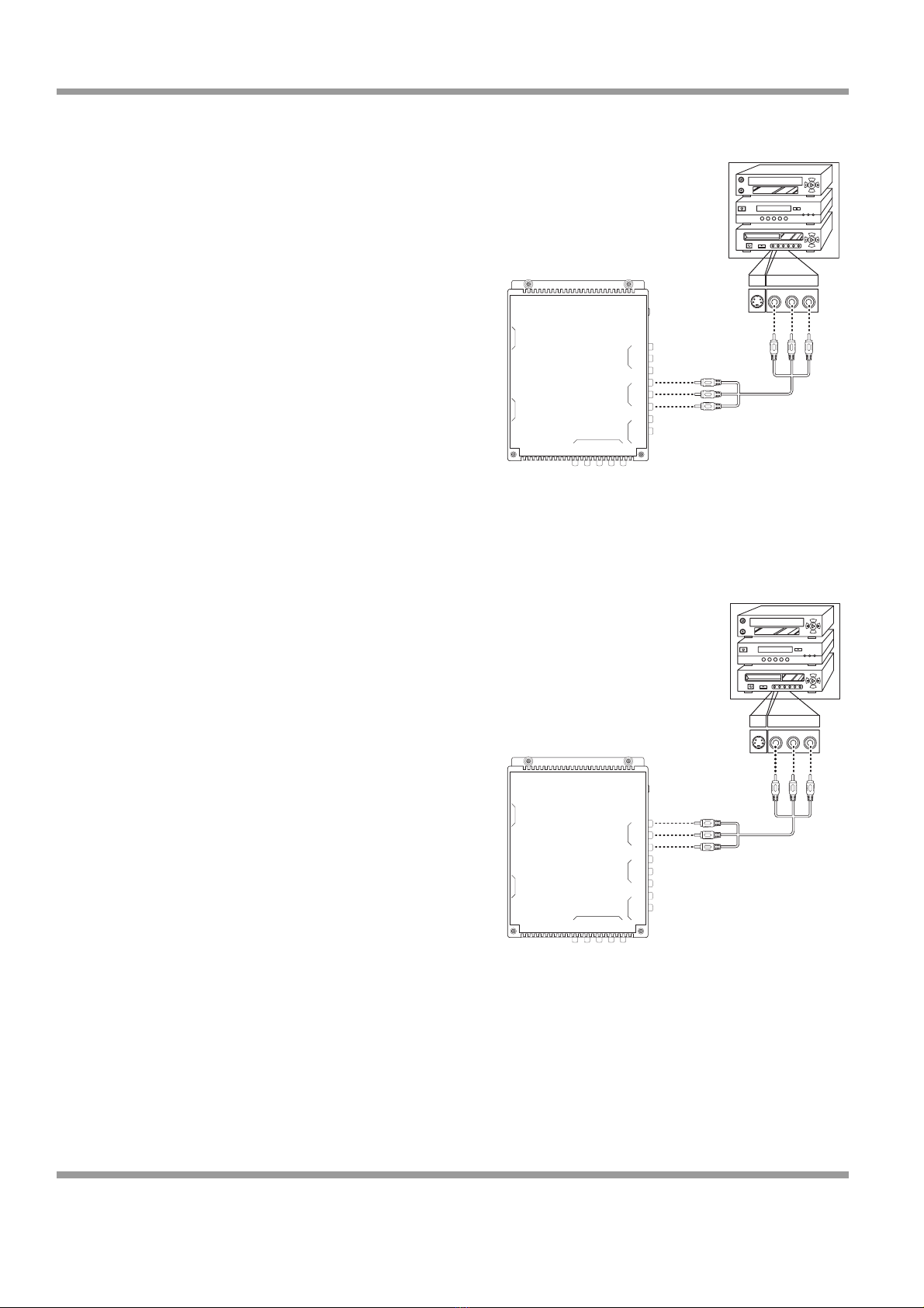
Component IN port
The COMPONENT IN port lets you connect your TV to
high quality video equipment such as a DVD player,
digital TV receiver, or digital satellite receiver. This port
consists of component audio (L, R) and video (YCbCr or
YPbPr) connectors and provides the highest picture
quality. To connect your A/V device to this port, do the
following:
1. Using a component video cable, connect the video
(YCbCr/YPbPr) jacks on the TV to the corresponding
video output jacks of your A/V device.
2. Using an audio cable, connect the audio (L, R) jacks
on the TV to the corresponding audio output jacks of
your A/V device.
It is strongly recommended that you connect the antenna using a 75
Ω
coaxial cable to get optimum
picture and sound quality. A 300
Ω
twin lead cable can be easily affected by radio and other
background noise, resulting in signal deterioration. When using a 300
Ω
twin lead cable, please keep
this cable as far away from the TV as possible.
ANT
R
RLY
Pb/Cb
Pr/Cr
PC/IN
PC AUDIO IN
SCART2 -IN
SCART1 -IN
L
R
L
R
L
S-VIDEO
VIDEO
VIDEO
S-IN
AV-I N
AV-OUT
COMPONENT IN
ANT
R
RLY
Pb/Cb
Pr/Cr
PC/IN
PC AUDIO IN
SCART2 -IN
SCART1 -IN
L
R
L
R
L
S-VIDEO
VIDEO
VIDEO
S-IN
AV-I N
AV-OUT
COMPONENT IN
YLRCbCr
Video Audio

12
SCART ports
The LCD TV has two SCART (SCART1, SCART2) ports for
connecting up to two SCART A/V devices with the LCD TV.
To connect an A/V device to the SCART port, use a SCART
cable to connect the device to either one of the SCART ports on
the rear panel of the LCD TV.
S-IN port
The S-IN port has been provided to enable you to connect
to devices with S-Video output such as DVD players,
digital cameras, satellite receivers, and so on. This port
produces picture very high picture quality. An A/V
device can be connected to this port as follows:
1. Using an S-Video cable, connect the video (S-Video)
jack on the TV to the corresponding S-Video output
jack of your A/V device.
2. Using an audio cable, connect the audio (L, R) jacks
on the TV to the corresponding audio output jacks of
your A/V device.
ANT
R
RLY
Pb/Cb
Pr/Cr
PC/IN
PC AUDIO IN
SCART2 -IN
SCART1 -IN
L
R
L
R
L
S-VIDEO
VIDEO
VIDEO
S-IN
AV-IN
AV-OUT
COMPONENT IN
ps
ANT
R
RLY
Pb/Cb
Pr/Cr
PC/IN
PC AUDIO IN
SCART2 -IN
SCART1 -IN
L
R
L
R
L
S-VIDEO
VIDEO
VIDEO
S-IN
AV-I N
AV-OUT
COMPONENT IN
AV-OUT
S-VIDEO
RL
VIDEO
13
AV IN port
The AV IN port supports composite video and provides
good quality video. To connect an A/V device such as a
VCR, VCD player, or DVD player, do the following:
1. Using a composite video cable, connect the video
(VIDEO) jack on the TV to the video output jack of
your A/V device.
2. Using an audio cable, connect the audio (L, R) jacks
on the TV to the corresponding audio output jacks of
your A/V device.
AV OUT port
Use the AV OUT port to connect your LCD TV to an A/V
device such as a DVD recorder, VCR, home theatre audio
equipment, and so on, as follows:
1. Using a composite video cable, connect the video
(VIDEO) jack on the TV to the video input jack of
your A/V device.
2. Using an audio cable, connect the audio (L, R) jacks
on the TV to the corresponding audio input jacks of
your A/V device.
ANT
R
RLY
Pb/Cb
Pr/Cr
PC/IN
PC AUDIO IN
SCART2 -IN
SCART1 -IN
L
R
L
R
L
S-VIDEO
VIDEO
VIDEO
S-IN
AV-IN
AV-OUT
COMPONENT IN
AV-O U T
RL
VIDEO
ANT
R
RLY
Pb/Cb
Pr/Cr
PC/IN
PC AUDIO IN
SCART2 -IN
SCART1 -IN
L
R
L
R
L
S-VIDEO
VIDEO
VIDEO
S-IN
AV-I N
AV-OUT
COMPONENT IN
AV-I N
RL
VIDEO

14
PC IN port
Connect your LCD TV to a PC or portable computer with
the PC IN port, to use the LCD TV as a monitor for your
PC. To connect to a PC, do the following:
1. Connect the video output of your PC or portable
computer to the PC IN (VGA) video input on the back
panel of the TV using a VGA cable.
2. Connect the Line out audio output of your PC to the
PC AUDIO IN jack of the TV.
ANT
R
RLY
Pb/Cb
Pr/Cr
PC/IN
PC AUDIO IN
SCART2 -IN
SCART1 -IN
L
R
L
R
L
S-VIDEO
VIDEO
VIDEO
S-IN
AV-IN
AV-OUT
COMPONENT IN
Table of contents
Other Ferguson TV manuals

Ferguson
Ferguson FTV28DFW5 User manual

Ferguson
Ferguson FTV21F2 User manual

Ferguson
Ferguson V32125L User manual

Ferguson
Ferguson Ferguson T 7025 UD User manual

Ferguson
Ferguson FTV21F2 User manual

Ferguson
Ferguson GTV69 User manual

Ferguson
Ferguson T5173GF User manual

Ferguson
Ferguson V22134LW User manual

Ferguson
Ferguson V22134L User manual

Ferguson
Ferguson PHT-1008 User manual
Popular TV manuals by other brands


Philips
Philips TPM16.1L Service manual

Panasonic
Panasonic TX-28HA1F operating instructions

Sony
Sony KV-19TS20 operating instructions

Mitsubishi Electric
Mitsubishi Electric LASERVUE L75-A94 Basic owner's guide

Panasonic
Panasonic TX-51PS72Z Service manual

Toshiba
Toshiba 46BL712G DIGITAL Series owner's manual


