Fermator MOD MC PREMIUM PM User manual

COMMERCIAL
LIFTS
EXISTING INSTALLATION
MAN-MMP2P0000ENGHP-01.2022 ENG
MOD MC PREMIUM PM
INSTALLATION MANUAL
Automatic horizontal sliding car door

Development and production by Fermator.
Attention: Before taking any action, testing or modication not covered in this manual you should notify
to our Technical Department.
Fermator accepts no responsibility in the event of any damage to the equipment described in this manual
and associated installation if the instructions given have not been followed.
Fermator reserves the right to modify the product specications in this technical brochure without any
prior notication.
For further information please contact our product department:
product@fermator.com

3
MOD MC PREMIUM PM
1 General
1.1 General.................................................................6
1.1.1 Equipment and tools .................................................6
1.1.2 Statements .........................................................6
1.1.3 Stainless steel cleaning and maintenance instructions .......................7
1.1.4 Environmental awareness .............................................7
1.1.5 Abbreviations .......................................................8
2 C2
2.1 List of components .......................................................9
2.1.1 C2 door ..........................................................10
2.1.2 Electronic module assembling options...................................11
2.1.3 Accessories .......................................................14
2.1.4 Optional components ................................................19
2.2 Assembly instructions ...................................................21
2.2.1 Sill installation .....................................................22
2.2.1.1 Aluminium 15 mm at channel sill assembly ........................22
2.2.1.2 Aluminium 8 mm recess at channel sill assembly ...................23
2.2.1.3 Steel at channel sill assembly ..................................24
2.2.1.4 Massive at channel sill assembly ...............................25
2.2.2 Operator installation .................................................26
2.2.2.1 Operator assembly ...........................................26
P 2.2.2.2 Operator adjustment ..........................................30
P 2.2.3 Clear opening (PL) verication and validation .............................31
2.2.4 Sheet metal panel ..................................................33
2.2.4.1 Sheet metal panel installation ...................................33
P 2.2.4.2 Sheet metal panel verication and validation .......................37
P 2.2.5 Eccentric wheel verication and validation ...............................39
P 2.2.6 Panel verication and validation .......................................40
2.2.7 Toe guard installation ................................................41
2.2.8 Other adjustments ..................................................43
P 2.2.8.1 CDL / clutch verication and validation ............................43
P 2.2.8.2 CDL / clutch adjustment .......................................45
P 2.2.8.3 Electrical contacts verication and validation .......................49
P 2.2.8.4 Coupling lateral view ..........................................51
Step of special interest to verication and regulation operations.
INDEX

4MOD MC PREMIUM PM
INDEX
3 T2
3.1 List of components ......................................................53
3.1.1 T2 door...........................................................54
3.1.2 Electronic module assembling options...................................55
3.1.3 Accessories .......................................................58
3.1.4 Optional components ................................................63
3.2 Assembly instructions ...................................................65
3.2.1 Sill installation .....................................................66
3.2.1.1 Aluminium 15 mm at channel sill assembly ........................66
3.2.1.2 Aluminium 8 mm recess at channel sill assembly ...................67
3.2.1.3 Steel at channel sill assembly ..................................68
3.2.1.4 Massive at channel sill assembly ...............................69
3.2.2 Operator installation .................................................70
3.2.2.1 Operator assembly ...........................................70
P 3.2.2.2 Operator adjustment ..........................................74
P 3.2.3 Clear opening (PL) verication and validation .............................75
3.2.4 Sheet metal panel ..................................................77
3.2.4.1 Sheet metal panel installation ...................................77
P 3.2.4.2 Sheet metal panel verication and validation .......................81
P 3.2.5 Eccentric wheel verication and validation ...............................83
P 3.2.6 Panel verication and validation .......................................84
3.2.7 Toe guard installation ................................................85
3.2.8 Other adjustments ..................................................87
P 3.2.8.1 CDL verication and validation ..................................87
P 3.2.8.2 CDL adjustment..............................................88
P 3.2.8.3 Electrical contacts verication and validation .......................89
P 3.2.8.4 Coupling lateral view ..........................................91
4 Optional components
4.1 Optional components C2 .................................................93
P 4.1.1 Egress device (From pit) .............................................94
P 4.1.2 Fixings to car roof operator assembling rails ..............................95
Step of special interest to verication and regulation operations.

5
MOD MC PREMIUM PM
4.2 Optional components T2 .................................................97
P 4.2.1 Egress device (From pit) .............................................98
P 4.2.2 Fixings to car roof operator assembling rails .............................99
5 Electronic module
5.1 VF7+ Relay electronic module ............................................101
5.1.1 Connections ......................................................102
5.2 VF7+ CAN electronic module.............................................105
5.2.1 Connections ......................................................106
5.3 VF5+ Electronic module .................................................109
5.3.1 Connections ......................................................110
5.4 Emergency power supplier ..............................................113
5.4.1 Connections ......................................................115
6 EU Declaration of conformity
6.1 EU Declaration of conformity.............................................117
INDEX
Step of special interest to verication and regulation operations.

6MOD MC PREMIUM PM
17 mm
13 mm
13 mm
4 mm
5 mm
19 mm
13 mm
15 mm
10 mm
+
-
mm
2.1.1 1.000,0
PRE START RECOMMENDATIONS
TOOLS
ICONS
SAFETY EQUIPMENT
1.1 GENERAL
11.1.1 EQUIPMENT AND TOOLS
1.1 GENERAL
11.1.2 STATEMENTS
Torque indicator. Optional. Verication and validation.
SUBSECTION NUMBER
Each step is numbered and
displayed under this format,
you will nd it at the upper-left
corner of the page.
DIMENSIONS
All dimension
measurements
are stated in mm.
THOUSANDS
In Fermator documentation,
the thousand symbol
is always a dot.
CAUTION
Before performing any action
on the existing operator, it
is imperative to disconnect
the electricity supply.

7
MOD MC PREMIUM PM
Use neutral liquid soap or products for glass cleaning (without bleach).
Use soft cloths and warm water.
Always clean following brush direction.
Do not use cleaning products that
contain bleach.
Do not rub or use scouring pads
or rough cloths.
1.1 GENERAL
11.1.3 STAINLESS STEEL CLEANING AND MAINTENANCE INSTRUCTIONS
1.1 GENERAL
11.1.4 ENVIRONMENTAL AWARENESS
To prevent possible damage to the environment when you decide to dispose of the packaging the waste should be disposed
of responsibly in accordance with the applicable environmental legislation.
Preventive cleaning to avoid corrosion: Regular cleaning will help in the removal of impurities and contaminants
which can cause corrosion. Marine, industrial, polluted and other corrosive climates require regular maintenance
to avoid excessive accumulation of dirt. Before cleaning the stainless steel remove any dust particles in order to
prevent friction of the particles on the surface.

8MOD MC PREMIUM PM
1.1 GENERAL
11.1.5 ABBREVIATIONS
DOOR
PARAMETERS
AFO Operator fastening point.
CDL Car door lock.
HL Clear height.
PL Clear opening.
DOOR
OPENING T2 2 panel side opening door.
ELECTRONIC
COMPONENTS
PM Permanent magnet motor.
VF Inverter.

MOD MC PREMIUM PM
LIST OF COMPONENTS
C2
2
10 MOD MC PREMIUM PM
1
Illustrative image,
see other options
in this manual.
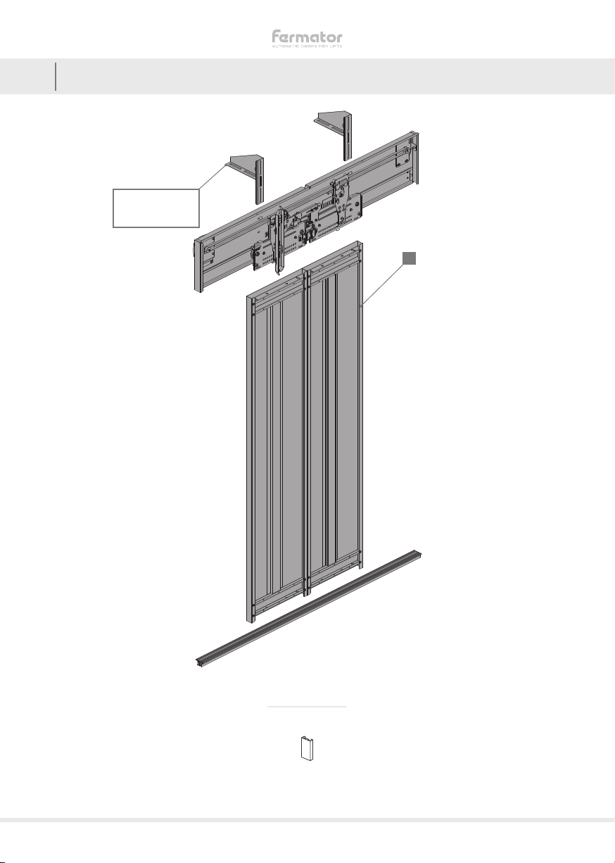
22.1.1 C2 DOOR
2.1 LIST OF COMPONENTS
STEEL PANELS
1
SHEET METAL

11
MOD MC PREMIUM PM
2.1 LIST OF COMPONENTS
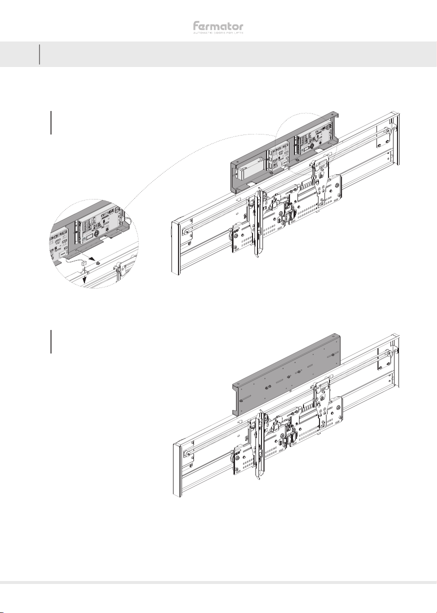
22.1.2 ELECTRONIC MODULE ASSEMBLING OPTIONS
AABOVE THE
OPERATOR FACING
THE LANDING DOOR
BABOVE THE
OPERATOR FACING
THE CAR ROOF
12 MOD MC PREMIUM PM
2.1 LIST OF COMPONENTS
22.1.2 ELECTRONIC MODULE ASSEMBLING OPTIONS
BABOVE THE
OPERATOR FACING
THE CAR ROOF
AABOVE THE
OPERATOR FACING
THE LANDING DOOR

13
MOD MC PREMIUM PM
2.1 LIST OF COMPONENTS
22.1.2 ELECTRONIC MODULE ASSEMBLING OPTIONS
BABOVE THE
OPERATOR FACING
THE CAR ROOF
AABOVE THE
OPERATOR FACING
THE LANDING DOOR

14 MOD MC PREMIUM PM
2.1 LIST OF COMPONENTS
22.1.3 ACCESSORIES
BRACKET ST ACCESSORIES PER SET
PL 700 - 950
PL 1.000 - 1.400
x2
x4 AM8 x 25
DIN 933 BM8 x 25
REDUCED HEAD CM8
NF E25-511 M DNUT M8
x4 x2 x6 x6
NUMBER OF SETS
PL 700 - 950 x1
PL 1.000 - 1.400 x2
BRACKET SD ACCESSORIES PER SET
PL 700 - 950
PL 1.000 - 1.400
x2
x4 AM8 x 25
DIN 933 BM8 x 25
REDUCED HEAD CM8
NF E25-511 M DNUT M8
x4 x2 x6 x6
NUMBER OF SETS
PL 700 - 950 x1
PL 1.000 - 1.400 x2
BRACKET EF ACCESSORIES PER SET
PL 700 - 950
PL 1.000 - 1.400
x2
x4 AM8 x 25
DIN 933 BM8 x 25
REDUCED HEAD CM8
NF E25-511 M DNUT M8
x4 x2 x6 x6
NUMBER OF SETS
PL 700 - 950 x1
PL 1.000 - 1.400 x2
BRACKET SE ACCESSORIES PER SET
PL 700 - 950
PL 1.000 - 1.400
x2
x4 AM8 x 25
DIN 933 BM8 x 25
REDUCED HEAD CM8
NF E25-511 M DNUT M8
x4 x2 x6 x6
NUMBER OF SETS
PL 700 - 950 x1
PL 1.000 - 1.400 x2
BRACKET ER ACCESSORIES PER SET
PL 700 - 950
PL 1.000 - 1.400
x2
x4 AM8 x 25
DIN 933 BM8 x 25
REDUCED HEAD CM8
DIN 125-A DM8 NUT
DIN 6923
x4 x2 x6 x6
NUMBER OF SETS
PL 700 - 950 x1
PL 1.000 - 1.400 x2

15
MOD MC PREMIUM PM
2.1 LIST OF COMPONENTS
22.1.3 ACCESSORIES
BRACKET EG ACCESSORIES PER SET
PL 700 - 950
PL 1.000 - 1.400
x2
x4 AM8 x 25
DIN 933 BM8 x 25
REDUCED HEAD CM8
NF E25-511 M DNUT M8
x4 x2 x6 x6
NUMBER OF SETS
PL 700 - 950 x1
PL 1.000 - 1.400 x2
REINFORCED
ALUMINIUM 15 mm
TRACK SILL
ACCESSORIES PER SET
AM10 x 16
DIN 933 BM10
DIN 6923
x4 x4
NUMBER OF SETS
700 ≤ PL ≤ 850 x1
900 ≤ PL ≤ 1.400 x2
REINFORCED
ALUMINIUM 8 mm
TRACK SILL
ACCESSORIES PER SET
AM10 x 16
DIN 933 BM10
DIN 6923
x4 x4
NUMBER OF SETS
700 ≤ PL ≤ 850 x1
900 ≤ PL ≤ 1.400 x2
ALUMINIUM 8 mm
TRACK SILL
ACCESSORIES PER SET
AM10 x 16
DIN 933 BM10
DIN 6923
x4 x4
NUMBER OF SETS
700 ≤ PL ≤ 850 x1
900 ≤ PL ≤ 1.400 x2
ALUMINIUM 15 mm
TRACK SILL
ACCESSORIES PER SET
AM10 x 16
DIN 933 BM10
DIN 6923
x4 x4
NUMBER OF SETS
700 ≤ PL ≤ 850 x1
900 ≤ PL ≤ 1.400 x2

16 MOD MC PREMIUM PM
2.1 LIST OF COMPONENTS
22.1.3 ACCESSORIES
MASSIVE SILL
ACCESSORIES PER SET
AM8 x 16
DIN 963 BM8
DIN 6923
x6 x6
NUMBER OF SETS
700 ≤ PL ≤ 950 x1
1.000 ≤ PL ≤ 1.400 x2
STEEL SILL
ACCESSORIES PER SET
AM8 x 16
DIN 6921
x6

17
MOD MC PREMIUM PM
2.1 LIST OF COMPONENTS
22.1.3 ACCESSORIES
SHEET METAL
PANEL
ACCESSORIES PER PANEL
A
85 mm REGULATION
SUPPORT
BM10
DIN 6923 CRECTANGULAR
WASHER DM10 x 25
DIN 6334
x2
700 ≤ PL ≤ 1.150 x2
1.200 ≤ PL ≤ 1.400 x3
700 ≤ PL ≤ 1.150 x2
1.200 ≤ PL ≤ 1.400 x3
700 ≤ PL ≤ 1.150 x4
1.200 ≤ PL ≤ 1.400 x6
700 ≤ PL ≤ 1.150 x2
1.200 ≤ PL ≤ 1.400 x3
E8 mm
GUIDE SHOE FM8 x 20
DIN 603 GM8
DIN 934
x2 x2 x2
HSEPARATOR IANTITURN
x2 x2
J15 mm
GUIDE SHOE
KWASHER M8 LM8 X 16
DIN 933 MM8
NF-E25-511 M
x2 x2 x2 x2
N0,8 mm SHIM
THICKNESS O0,5 mm SHIM
THICKNESS
x2 x4

18 MOD MC PREMIUM PM
2.1 LIST OF COMPONENTS
22.1.3 ACCESSORIES
CM6 x 15
BOLT DM6 x 5
DIN 966
x2 x2
NUMBER OF SETS
700 ≤ PL ≤ 1.400 x1
700 ≤ PL ≤ 850 x2
900 ≤ PL ≤ 1.150 x3
1.150 ≤ PL ≤ 1.400 x4
TOE GUARD ACCESSORIES PER SET
x1
AM6 x 10
DIN 966 BM6
DIN 6923
x6 x8

19
MOD MC PREMIUM PM
2.1 LIST OF COMPONENTS
22.1.4 OPTIONAL COMPONENTS
RAIL ACCESSORIES PER SET
AM12 x 40
DIN 603 BFIXATION
PLATE CM12
NF E25-511 M DM12
DIN 934
x4 x4 x4 x4
NUMBER OF SETS
PL 700 - 950 x1
PL 1.000 - 1.400 x2

Table of contents
Popular Garage Door Opener manuals by other brands

Craftsman
Craftsman 139.53976SRT owner's manual

Guardian
Guardian DCR2 Installation instructions and owner's manual

Sears
Sears Craftsman 139.54920 owner's manual

tau
tau 650ESE installation guide

Chamberlain
Chamberlain LiftMaster LM60 Assembly and operating instructions

Brano
Brano Pro-Alpha Infinity Setup instructions


Wayne-Dalton
Wayne-Dalton Flush 42 quick start guide

Craftsman
Craftsman 139.53990D owner's manual

Automatic Technology
Automatic Technology SecuraLift GDO-7V1 Owner's installation instructions

Craftsman
Craftsman 139.53993DM owner's manual

Proteco
Proteco Q80S instruction manual

MyQ
MyQ CHAMBERLAIN B4603TC user guide