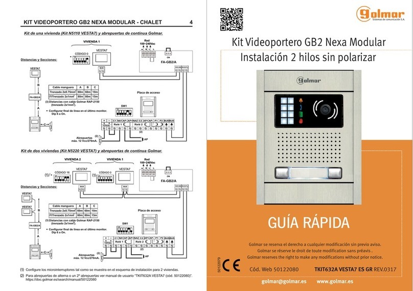
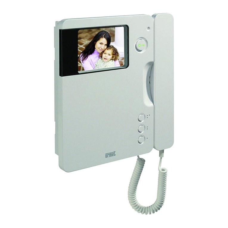
Fermvision FVQ-6030APP User guide

1
2WIRESYSTEM
FVQ‐6030APPKIT
&
FVQ‐6030KIT
VIDEODOORPHONESYSTEM
FVQ
‐
6016KP
‐
F
FVQ‐6013/9013WIFI
Pleasereadthemanualcarefullybeforeusingtheproduct.
Pleasenotethatimagesandsketchesinthismanualmaybedifferentfromtheactualproducts
INSTALLERMANUAL

2
Contents
MonitorDescription......................................................................................................................................................3
DoorStationDescription...............................................................................................................................................4
Addressingthemonitors(Whenusingmorethanonemonitor):................................................................................5
ImpedanceSwitch.........................................................................................................................................................5
ViewingMultipleDoorStationsOnTheMonitor.........................................................................................................6
WiringDiagrams............................................................................................................................................................7
LockWiring..................................................................................................................................................................16
SummaryKeypaddoorstationcodes.........................................................................................................................23
DetailedKeypadCodes...............................................................................................................................................24
Wi‐FiConfiguration.....................................................................................................................................................27
Dimensions
FrontPlate:219.5x120mm(HxW)
BackingBox:203.5x104x46mm(HxWXD)
Makesuretherecessboxiscompletelysealedtopreventwaterpenetration

3
MonitorDescription
NO Name Description
1 MicroSD SocketforMicroSD
2 PowerIndicator WhiteLEDwhenpoweron
3 DoNotDisturb PurpleLEDwhenfunctionisenabled
4 MessageIndicator GreenLEDwhenyouhavemissedcalls
5 Microphone
6 Screen 7InchDigitalTFTLCD
7 Switch Bit1‐Bit5–Homeaddress
Bit6–Bit7–Masterandslaveselection
8 ConnectionPoint BUS1&BUS2–Systemconnectionbus
24V&GND–ExternalPowersupply(Notneeded)
COM&NO–Connectorforexternalspeaker
SW+&SW‐:Connectorforexternaldoorbell
9 Speaker

4
DoorStationDescription
NO Name
1 StatusIndicator
2 Camera
3 Speaker
4 Keypad
5 LED’s(Sensorlocatedinmiddle)
6 Microphone
7 Fixingscrew
8 ConnectionPort

5
Addressing the monitors (When using more than one monitor):
Thisiscontrolledbydipswitch6&7onthebackofthemonitor
Type DipSwitchSetting
MasterMonitor
SlaveMonitor1
SlaveMonitor2
SlaveMonitor3
Impedance Switch
Onlyturntotheonpositionwhenthemonitoristheendofline.Thisiscontrolledbydipswitch8onthebackof
themonitor.
Type DipSwitchSetting
ImpedanceOf
f
ImpedanceOn
67
ON
67
ON
67
ON
67
ON
8
ON
8
ON

6
Viewing Multiple Door Stations On The Monitor
Whenusingmultipledoorstationyouneedtoactivatethedoorstationtoviewonthemonitors.
Usingthesettingsmenuoneachindividualmonitortypeinthefollowingcodedependinghowmanydoorstation
youhave.(Default4DoorStations)
DoorStation Code(On) Code(Off)
DS1 0111 0110
DS2 0131 0130
DS3 0151 0150
DS4 0171 0170

7
WiringDiagrams
Notes:
Whenusingmorethan1doorstationyourequirea4branchDoorstationmoduleFVQ‐6012D
Whenusingmorethan1monitorinstarconfigurationyourequirea4branchmonitormoduleFVQ‐6011M
DoorStationisaddressedasnumber1bydefault

8
1DoorStationto4Monitors(StarConfiguration)
6011M
BUS
FRONTDOORSTATION#1
BUS( IM) BUS( DS)
PC6
10AGP0
Keypad Code
1234#, 11#, 1#, *.
M
O
ON

9
MONITOR#1 MONITOR#2 MONITOR#3 MONITOR#4
BU S 1BU S 2 BUS1BU S2 BU S 1 BU S 2 BU S 1 BU S 2
Master Slave 1 Slave 2 Slave 3
87
ON
65 4321
ON
87
ON
654321 87
ON
65 4321
ON
87
ON
654321
ON
ON

10
1DoorStationto3Monitors(Series)
BUS
FRONTDOORSTATION#1
BU S( IM) BUS( DS)
PC6
10AGP0
Keypad Code
1234#, 11#, 1#, *.

11
MONITOR#1 MONITOR#2 MONITOR#3
BU S 1 BU S 2 BU S 1 BU S 2 BU S 1 BU S 2
Master Slave 1 Slave 2
87
ON
654321
ON
87
ON
6543
21
ON
87
ON
654321
ON

12
4DoorStationto4Monitors(StarConfiguration)
DBC-4S
A B C D
BUS
FRONTDOORSTATION #1
BUS
FRONTDOORSTATION #2
BUS
FRONTDOORSTATION #3
BUS
FRONTDOORSTATION #4
6011 M
BUS(IM ) BUS(DS)
PC6
10AGP 0
6012 D
Keypad Code
1234#, 11#, 1#, *.
Keypad Code
1234#, 11#, 2#, *.
Keypad Code
1234#, 11#, 3#, *.
Keypad Code
1234#, 11#, 4#, *.
Ma
s
87
ON
6
ON

13
MONITOR #1 MONI T OR #2 MONI TOR #3 MONI TOR #4
BUS1BUS2 BUS 1BUS2 BUS1BUS2 BUS 1BUS2
Master Slave 1 Slave2 Slave 3
87
ON
654321
ON
87
ON
654321 87
ON
654321
ON
87
ON
654321
ON
ON

14
4DoorStationto3Monitors(Series)
DBC-4S
A B C D
BUS
FRONTDOORSTATION#1
BUS
FRONTDOORSTATION#2
BUS
FRONTDOORSTATION#3
BUS
FRONTDOORSTATION#4
BUS(I M) BUS(DS)
PC6
10AGP 0
6012 D
Keypad Code
1234#, 11#, 1#, *.
Keypad Code
1234#, 11#, 2#, *.
Keypad Code
1234#, 11#, 3#, *.
Keypad Code
1234#, 11#, 4#, *.

15
MONITOR#1 MONITOR#2 MONITOR#3
BUS1BUS2 BUS 1BUS2 BUS1BUS 2
Master Slave 1 Slave 2
87
ON
654321
ON
87
ON
654321
ON
87
ON
65 4321
ON

16
LockWiring
Thesystemhas2Locks
Lock1–12VDC(250mA)Outputonexitordoorrelease
o Lock1isonlypowertounlock
Lock2–DryCollectorthatcanbetoggledbetweenNormallyOpenorNormallyClosed
TheExitbuttoncanbeconfiguredin3Modes(DefaultisLock1&Lock2)
OnlyLock1
OnlyLock2
Lock1andLock2(DEFAULTMODE)

17
PowertoUnlock PowertoLock
Lock1 N/A
Lock2
ExitButtonToOpen
Lock1
Lock2

18
PowertoUnlock PowertoLock
Lock1 N/A
Lock2
ExitButtonToOpen
Lock1
Lock2
EGRESS
BUTTON
88406‐
12VDC
‐
+
10AGP0
EXIT BUTTON LOCK 2
1234#, 05#, 1#, *.

19
PowertoUnlock PowertoLock
Lock1 N/A
Lock2
ExitButtonToOpen
Lock1
Lock2
NormallyClosed
EGRESS
BUTTON
88406‐
12VDC
‐
+
10AGP0
EXIT BUTTON LOCK 2
1234#, 05#, 1#, *.

20
PowertoUnlock PowertoLock
Lock1 N/A
Lock2
ExitButtonToOpen
Lock1
Lock2
EGRESS
BUTTON
88406 ‐
12VDC
‐
+
10AGP0
EXIT BUTTON FOR BOTH
LOCKS
1234#, 05#, 2#, *.
This manual suits for next models
1
Table of contents
