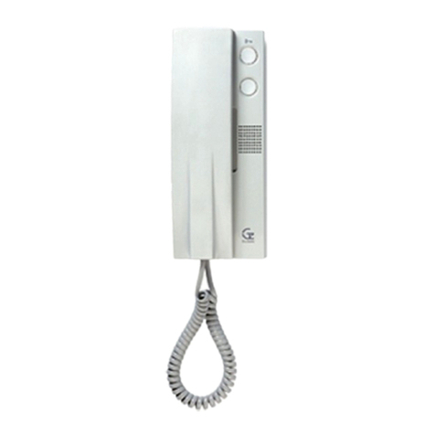
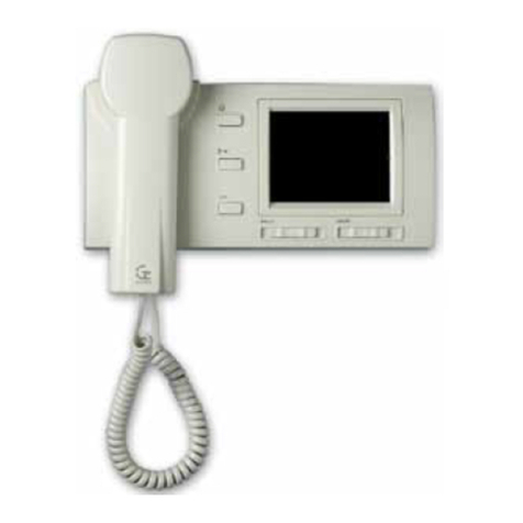
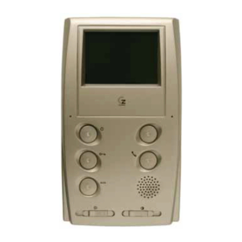
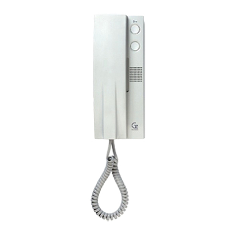
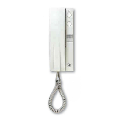
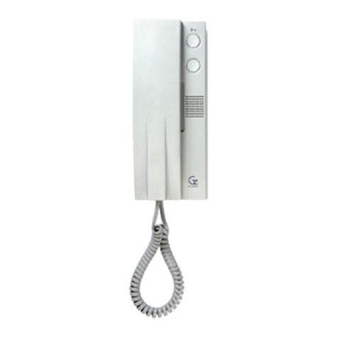
Guinaz T1140V2 User manual

GUÍA DE INSTALACIÓN INSTALLATION GUIDE
KITS DIGITALES AUDIO
DIGITAL AUDIO KITS

ÍNDICE. INDEX.
2
1. Descripción de los equipos.
Description of the equipment........................................................................................................................................3
1.1 Descripción placa calle.
Description of the street panel..............................................................................................................................3
1.2 Descripción eléfono T1140V2.
Description of telephone T1140 2.......................................................................................................................3
1.3 Generalidades del sis ema digi al Guinaz.
General properties of the digital system by Guinaz..............................................................................................4
2. Esquemas de conexión.
Connection diagrams....................................................................................................................................................4
2.1 Esquema unifilar y abla de secciones.
Single wire diagram and section table.................................................................................................................4
2.2 Esquema de conexiones para ki s digi ales de audio.
Connection diagrams for digital audio kits...........................................................................................................5
2.3 Ins alación eléfono suple orio.
Installation of a supplementary telephone............................................................................................................6
2.4 Conexión de abrepuer as de corrien e al erna.
Connection of alternating current door openers...................................................................................................6
3. Ins alación de los equipos.
Installation of the equipment..........................................................................................................................................7
3.1 Ins alación placa calle.
Installation of the street panel...............................................................................................................................7
3.2 Colocación de los arje eros.
Placement of name tags......................................................................................................................................8
3.3 Recomendaciones de ins alación de la placa calle.
Recommendations for street panel installation.....................................................................................................8
3.4 Ins alación fuen e de alimen ación.
Power supply installation......................................................................................................................................9
3.5 Ins alación eléfono T1140V2.
Installation of telephone T1140 2........................................................................................................................9
3.6 Recomendaciones ins alación eléfonos.
Recommendations for telephone installation.....................................................................................................10
4. Configuración de los equipos.
Configuration of the equipment...................................................................................................................................10
4.1 Configuración del grupo con rol audio (placa calle).
Configuration of the audio control group (street panel)......................................................................................10
4.2 Configuración de microin errup ores en eléfonos.
Configuration of micro-switches in telephones....................................................................................................11
4.3 Módulos pulsadores (placa calle): asignación de códigos de llamada.
Pushbutton modules (street panel): call code assignation..................................................................................11
5. Funcionamien o general.
General operating........................................................................................................................................................12
5.1 Función de vigilancia.
Surveillance function..........................................................................................................................................12
5.2 Bornas 12 y 13: pulsador auxiliar.
Terminals 12 and 13: supplementary pushbutton..............................................................................................12
6. Pues a en marcha y solución de problemas.
Start-up and problem resolution..................................................................................................................................12
G503129 - R01

3
1. DESCRIPCIÓN DE LOS EQUIPOS.
DESCRIPTION OF THE EQUIPMENT.
Los ki s de por ero digi ales de Guinaz cons an de placa calle,
eléfonos, fuen e de alimen ación y abrepuer as de corrien e
con inua. Exis en diferen es referencias de ki de por ero digi al
según varios fac ores como son el color de placa calle, el número
de viviendas, o si incluyen abrepuer as o no. Consul e el ca álogo
de produc os Guinaz para elegir la referencia que mejor se adap e
a sus necesidades y preferencias.
El fron al de la placa calle es una placa compac a en la que van
suje os el grupo con rol audio y los módulos pulsadores. Según
el modelo de ki , es a placa se sirve en color gris an raci a o en
color aluminio.
La fuen e de alimen ación posee un rango de ensión de en rada
de 90-264V, y en rega en su salida 17V de corrien e con inua con
los que se alimen a al res o de equipos de la ins alación.
El grupo con rol audio de la placa calle admi e la colocación de
un pulsador ex erior para ac ivar el abrepuer as. En odos los ki s
audio digi ales se puede ins alar un abrepuer as de corrien e
con inua (12Vdc 400mA máximo) o un abrepuer as de corrien e
al erna (12Vac 1A máximo). Más adelan e se indica cómo se
conec an los dos ipos. En el caso de los ki s que incorporan
abrepuer as de serie, siempre son abrepuer as de corrien e
con inua.
Es os equipos son para uso exclusivo en ins alaciones de por eros
GUINAZ. Su ins alación debe realizarse al y como se especifica
en es a guía y aplicando la reglamen ación vigen e.
The digital entryphone kits by Guinaz are made up of a street
panel, telephones, a power supply and a direct current door
opener. There are different digital entryphone kit references
according to several factors such as the colour of the street
panel, the number of dwellings, or whether they include door
opener or not. Check the Guinaz product catalogue to choose
the reference that best adapts to your needs and preferences.
The front of the street panel is a compact panel to which the
audio control group and the pushbutton modules are attached.
According to the kit model, this panel is provided in anthracite
grey or aluminium colours.
The power supply has a 90-264 input voltage range, delivering
at output 17 direct current to supply all the rest of the equipment
in the installation.
The audio control group of the street panel allows placing an
external pushbutton to activate the door opener. A direct current
door opener (maximum 12 dc 400mA) or an alternating current
door opener (maximum 12 ac 1A) can be installed in all the
digital audio kits. How these two kits are connected is indicated
below. In the case of kits including a door opener as standard,
these door openers will always use direct current.
These sets of equipment are for exclusive use in GUINAZ
entryphone installations. They will be installed as specified in
this guide while applying the legislation in force.
1.1 DESCRIPCIÓN PLACA CALLE.
DESCRIPTION OF THE STREET PANEL.
Pulsador abrepuer as: sirve para abrir la puer a.
Door opener pushbutton: this is used to open the door.
1.2 DESCRIPCIÓN TELÉFONO T1140V2.
DESCRIPTION TELEPHONE T1140V2.
Pulsador auxiliar: se ra a de un con ac o libre de po encial, que admi e 17Vdc de ensión máxima
y 40mA de corrien e máxima, y que puede u ilizarse para ac ivar funciones ajenas a la ins alación.
Supplementary pushbutton: this is a potential-free contact, that admits a maximum voltage of 17 dc
and a maximum current of 40mA, and which may be used to activate functions not related to the
installation.
Grupo con rol audio: ges iona el funcionamien o de odo el sis ema. Es á conec ado a los módulos
pulsadores median e un la iguillo. Con los eléfonos de las viviendas se conec a median e un bus
de res hilos (1M, 2M, 3M), a ravés del cual se ransmi en los da os, la señal de audio y la alimen ación.
El grupo con rol audio ambién genera la señal para la aper ura del abrepuer as.
Audio control group: this manages the operating of the entire system. It is connected to the pushbutton
modules by means of a connector. It is connected to the telephones of dwellings by means of a
three-wire bus (1M, 2M, 3M), via which the data, the audio signal and the power supply are transmitted.
The audio control group also generates the door opening signal.
Módulos pulsadores: con ienen los pulsadores de llamada y los arje eros de información. Los
arje eros es án iluminados permanen emen e. Es án conec ados median e un la iguillo al grupo
con rol audio. Hay varios modelos de módulos pulsadores según el número de viviendas del ki .
Pushbutton modules: these contain the call pushbuttons and the information tags. The tags will be
lit up permanently. They are connected by means of a connector to the audio control group. There
are several pushbutton module models according to the number of dwellings included in the kit.
G503129 - R01
4
23
Bus Audio/Da os
(Hilos 1M, 2M y 3M)
Audio/Data bus
(wires 1M, 2M & 3M)
33
2
The cableform of the digital system by Guinaz consists of a 3-
wire bus for audio, data and power supply signals, interconnected
with all the equipment of the installation. The cross-section of the
cables will be adequate for the instalación to be carried out.
Wire number 1M is positive in the power supply of the equipment.
Wire number 2M is the ground for the entire digital system. Wire
number 3M is in charge of transporting the data according to the
digital communication protocol of the system and also the audio
signal when communications are established between two sets
of equipment.
Wire 1M: power supply +17 dc
Wire 2M: ground
Wire 3M: communication (data/audio)
Among the features of the digital system by Guinaz are that one
can rely on total secrecy in communication, the possibility of
performing surveillance from a dwelling with active audio signal,
door opening without the need to call previously, etc.
Simple installations with a single access and more complex
installations with multiple secondary accesses can be
performed with the digital system by Guinaz, without the
need to include additional modules or signal exchanges
between the street panels.
El cableado del sis ema digi al de Guinaz consis e en un bus
de 3 hilos para las señales de audio, da os y alimen ación, con
los que se in erconec an odos los equipos de la ins alación. La
sección de los cables debe ser la adecuada para la ins alación
a realizar.
El hilo número 1M es el posi ivo de alimen ación para los equipos.
El hilo número 2M es la masa de odo el sis ema digi al. El hilo
número 3M es el encargado de ranspor ar los da os según el
pro ocolo de comunicación digi al del sis ema, y ambién la
señal de audio cuando se es ablece comunicación en re dos
equipos.
Hilo 1M: alimen ación +17Vdc
Hilo 2M: masa
Hilo 3M: comunicación (da os/audio)
En re las pres aciones del sis ema digi al Guinaz se pueden
con ar el secre o o al de comunicación, la posibilidad de hacer
vigilancia desde una vivienda con señal de audio ac iva, la
aper ura de la puer a sin llamada previa, e c.
Con el sistema digital de Guinaz se pueden realizar
instalaciones sencillas con un único acceso e instalaciones
más complejas con múltiples accesos secundarios, sin
necesidad de incluir módulos adicionales o
intercambiadores de señal entre placas calle.
2.1 ESQUEMA UNIFILAR Y TA LA DE SECCIONES.
SINGLE WIRE DIAGRAM AND SECTION TA LE.
2. ESQUEMAS DE CONEXIÓN.
CONNECTION DIAGRAMS.
Estas tablas están calculadas para un teléfono por i ienda e indican la distancia máxima entre la placa calle y los
teléfonos de las i iendas según la sección de cable a instalar. En el caso de ins alaciones con eléfonos suple orios, las
dis ancias máximas para cada sección varían (consul e el pun o 2.3).
These tables are calculated for one telephone per dwelling and indicate the maximum distance between the street
panel and the telephones in dwellings according to the cable cross-section to be installed. The maximum distances for
each section will vary in the case of installations with supplementary telephones (see point 2.3).
Conexiones
Connections
1M, 2M, 3M
Secciones (mm²)
Sections mm²)
Nº de hilos
Nº of wires
3 100 m
Distancias máximas (metros)
Maximum distances meters)
300 m 400 m200 m
1.3 GENERALIDADES DEL SISTEMA DIGITAL GUINAZ.
GENERAL PROPERTIES OF THE DIGITAL SYSTEM Y GUINAZ
0,22 1 1,50,5
G503129 - R01

5
Abrepuer as (12 Vdc, 400mA máx.)
Door opener (12 dc, max 400mA)
2.2 ESQUEMA DE CONEXIONES PARA KITS DIGITALES DE AUDIO.
CONNECTION DIAGRAMS FOR DIGITAL AUDIO KITS.
CABLE ALIMENTACIÓN. POWER SUPPLY CABLE.
CABLE SEÑAL. SIGNAL CABLE.
1M
2M
12
13
3M
Pulsador auxiliar abrepuer as
Auxiliary door opener push-button
Con ac os
pulsador auxiliar
Auxiliary
push-button contacts
T1140V2
Teléfono 1
Telephone 1
1M
2M
3M
+12
C
NO
IN
OUT
V/H
M/L
M/L
V/H
-
Para ins alar abrepuer as de al erna véase pun o 2.4
Please see point 2.4 To install alternating current door opener
1234
Configuración placa calle
Configuration of street panel
Placa principal
Main panel
Conexión median e la iguillos:
Connection with straps:
G3260 - GD2XX
Sucesivamen e en re modulos
pulsadores
Successively between push button
modules
-
+
1M
2M
12
13
3M
Con ac os
pulsador auxiliar
Auxiliary
push-button contacts
T1140V2
Teléfono n
Telephone n
The power supply of the system is carried out by means of the
cables joining terminals 1 and 2 of the power supply with terminals
1M and 2M of the audio control group in the street panel. The
communication bus is formed by the three cables leaving terminals
1M, 2M and 3M of the audio control group in the street panel, and
will be connected to terminals 1M, 2M and 3M, respectively, of
the telephones in dwellings.
The connection between the street panel and the door opener is
made using two cables (NO and terminals of the audio control
group). Terminals +12 and C will connect with each other
by means of a cable. A supplementary external pushbutton may
be connected between terminals C and NO in order to activate
the door opener. The time the door opener is activated when the
supplementary external pushbutton is pressed does not have a
timer, that is to say, it will only remain active while this external
pushbutton is being pressed.
La alimen ación del sis ema se realiza median e los cables que
unen las bornas 1 y 2 de la fuen e de alimen ación con las bornas
1M y 2M del grupo con rol audio de la placa calle. El bus de
comunicación lo forman los res cables que par en de las bornas
1M, 2M y 3M del grupo con rol audio de la placa calle, y que se
han de conec ar a las bornas 1M, 2M y 3M, respec ivamen e,
de los eléfonos de la viviendas.
La conexión en re la placa calle y el abrepuer as se realiza
median e dos cables (bornas NO y del grupo con rol audio).
Las bornas +12 y C deben conectarse entre sí con un
cable. Se puede conec ar un pulsador auxiliar ex erno para
ac ivar el abrepuer as en re las bornas C y NO. El iempo de
ac ivación del abrepuer as, cuando se acciona el pulsador auxiliar
ex erno, no es á emporizado; es decir, el abrepuer as sólo es á
ac ivo mien ras se man iene pulsado es e pulsador ex erno.
G503129 - R01
220 Vac
F1334
1
INPUT
2

6
Conexiones
Connections
1M, 2M, 3M
Secciones (mm²)
Sections mm²)
Nº de hilos
Nº of wires
3
50 m
Distancias máximas (metros)
Maximum distances meters)
200 m 300 m100 m
2.3 INSTALACIÓN TELÉFONO SUPLETORIO.
INSTALLATION OF A SUPPLEMENTARY TELEPHONE.
The micro-switches of the supplementary telephone are configured
as follows:
The first 8 micro-switches are placed in the same way as in the
main telephone, since the number of dwellings should be the
same.
Micro-switch 9 is placed in ON ® supplementary position.
The values of the section table in point 2.1 will vary according to
the amount of supplementary telephones installed. The following
tables indicate the maximum distances according to the cable
cross-section for installations with a main telephone and 1, 2 or 3
supplementary telephones per dwelling:
Los microin errup ores del eléfono suple orio se configuran como
sigue:
Los 8 primeros microin errup ores se colocan al como es án
en el eléfono principal, ya que el número de vivienda debe
ser el mismo.
El microin errup or 9 se coloca en la posición ON ® suple orio.
Según la can idad de eléfonos suple orios ins alados, los valores
de la abla de secciones del pun o 2.1 varían. Las ablas siguien es
indican las dis ancias máximas según la sección de cable para
ins alaciones con un eléfono principal más 1, 2 ó 3 eléfonos
suple orios por vivienda:
All the digital audio kits allow the connection of an alternating current
door opener. The connection between the street panel and the
door opener is carried in a different manner, it being necessary to
add a new F1318 power supply. 12 ac alternating current with a
maximum current of 1A can be activated with this configuration.
The diagram shown below provides details on the connection
between the digital audio control group of the street panel, power
supply F1318 and the alternating current door opener:
El iempo de ac ivación del abrepuer as, cuando se acciona el
pulsador auxiliar ex erno, no es á emporizado; es decir, el
abrepuer as sólo es á ac ivo mien ras se man iene pulsado es e
pulsador ex erno.
2.4 CONEXIÓN DE A REPUERTAS DE CORRIENTE ALTERNA.
CONNECTION OF ALTERNATING CURRENT DOOR OPENERS.
Todos los ki s de audio digi ales admi en la conexión de un
abrepuer as de corrien e al erna. La conexión en re la placa calle
y el abrepuer as se realiza de forma diferen e y es preciso añadir
una fuen e de alimen ación F1318. Con es a configuración se
pueden ac ivar abrepuer as de corrien e al erna de 12Vac y 1A de
corrien e máxima. El esquema mos rado a con inuación de alla la
conexión en re el grupo con rol audio digi al de la placa calle, la
fuen e de alimen ación F1318 y el abrepuer as de corrien e al erna:
The time the door opener is activated when the supplementary
external pushbutton is pressed does not have a timer, that is to
say, it will only remain active while this external pushbutton is being
pressed.
1 Tel. Principal MainTel. + 1 Tel. Supletorio Supplementary Tel.
0,22 1 1,50,5
35 m 135 m 200 m70 m
25 m 100 m 150 m50 m
1 Tel. Principal MainTel. + 2 Tel. Supletorios Supplementary Tel.
1 Tel. Principal MainTel. + 3 Tel. Supletorios Supplementary Tel.
G503129 - R01

7
Suje e la placa calle median e dos ornillos.
Attach the plate with two screws.
Para apertura a la derecha:
A) Suel e el ornillo izquierdo y afloje el derecho.
B) Desplace la placa calle hacia la izquierda y fron almen e 1,5 mm.
C) Gire la placa calle.
For opening to the right:
A) Unscrew left screw and lossen the right one.
B) Displace the street panel to the left and forward 1.5 mm.
C) Turn the street panel.
Coloque la caja empo rable.
Place the flush-mounted box.
12
3
3. INSTALACIÓN DE LOS EQUIPOS.
INSTALLATION OF THE EQUIPMENT.
3.1 INSTALACIÓN PLACA CALLE.
INSTALLATION OF THE STREET PANEL.
Para apertura a la izquierda:
A) Suel e el ornillo derecho y afloje el izquierdo.
B) Desplace la placa calle hacia la derecha y fron almen e 1,5 mm.
C) Gire la placa calle.
For opening to the left:
A) Unscrew right screw and lossen the left one.
B) Displace the panel to the right and forward 1.5 mm.
C) Turn the street panel.
Conec e los cables al grupo con rol audio Configure la
placa calle (véase el pun o 4.1).
Connect the cable to the audio control unit. Configure
the street panel (see point 4.1).
Ajus e el volumen de audio en placa calle y vivienda.
Adjust the sound volume in the street plate and dwelling.
5
4
6
G503129 - R01

8
IMPORTANTE: COLOCAR LAS TAPAS SUPERIOR E INFERIOR
ANTES DE CERRAR LA PLACA CALLE. PRESIONAR HASTA OIR
EL "CLIP".
IMPORTANT: PLACE THE UPPER AND LOWER CO ERS BEFORE
CLOSING THE STREET PANEL PRESS UNTIL YOU HEAR "CLIP".
Cierre la placa calle con aprie e de ambos ornillos.
Close the street panel and tighten both screws.
78
ONCE THE STREET PANEL IS INSTALLED, REMEMBER:
TO OPEN THE STREET PANEL IT IS NOT NECESSARY
TO REMOVE THE UPPER AND LOWER COVERS. It is
only necessary to unscrew one screw and to loosen the
other (see sections 3 and 4).
THE UPPER AND LOWER COVERS CAN ONLY BE FITTED
IN OR REMOVED WITH THE STREET PANEL OPEN.
Once this is closed, the anchoring clips of the covers are
left trapped by the panel itself in order to avoid actions of
vandalism.
UNA VEZ INSTALADA LA PLACA CALLE, RECUERDE QUE:
PARA ABRIR LA PLACA CALLE NO HAY QUE QUITAR
LAS TAPAS SUPERIOR E INFERIOR. Sólo es necesario
sol ar un ornillo y aflojar el o ro (consul e los apar ados 3
y 4).
LAS TAPAS SUPERIOR E INFERIOR SÓLO PUEDEN
PONERSE O QUITARSE CON LA PLACA CALLE
ABIERTA. Una vez cerrada és a, las pa illas de anclaje de
las apas quedan a rapadas por la propia placa para evi ar
acciones vandálicas.
3.2 COLOCACIÓN DE LOS TARJETEROS.
PLACEMENT OF NAME TAGS.
La placa de calle es á suficien emen e pro egida
de las condiciones a mosféricas. Sin embargo, es
convenien e ins alarla en un lugar en que no afec en
direc amen e agen es como la lluvia, humedad, e c.
Cuando la placa calle es é expues a a la in emperie
se recomienda ins alarla sobre un marco visera. En
el caso de superficies no lisas, donde la placa calle
o el marco visera no queden perfec amen e sellados
median e las jun as que incorporan, se recomienda
aplicar algún sellan e en oda la par e superior de
la placa calle o marco visera para evi ar en radas
de agua que puedan dañar el equipo.
The street panel is sufficiently protected against
atmospheric conditions. However, it is
recommendable to install it in a place where agents
such as rain, humidity, etc. cannot affect it.
When the plate is exposed to the elements it is
recommendable to install it with a visor frame. In
the case of surfaces that are not smooth, where
the street plate or visor frame are not perfectly
sealed with the joints that are incorporated, then
some sort of sealer should be applied throughout
the entire upper part of the street plate or visor
frame to thus avoid water from penetrating and
damaging the equipment.
3.3 RECOMENDACIONES DE INSTALACIÓN DE LA PLACA CALLE.
RECOMMENDATIONS FOR STREET PANEL INSTALLATION.
La manipulación in erna de los equipos sólo puede realizarse por personal especializado y siempre con el equipo desconec ado de
la alimen ación.
Internal handling of the equipment may only be performed by specialised personnel, always once the equipment has been disconnected
from the power supply.
Ex racción del arje ero del
módulo de pulsadores
colocado en placa calle.
Extract the name card unit
from the push-button
module of the street panel.
Separar ranslúcido de
cris al.
Separate translucent glass
part.
In roducción del arje ero.
Insert the card.
Inser ar en módulo de
pulsadores has a clipar.
Insert in the push-button
module until it clips in.
1234
G503129 - R01

9
3.4 INSTALACIÓN FUENTE DE ALIMENTACIÓN.
POWER SUPPLY INSTALLATION.
3.5 INSTALACIÓN TELÉFONO T1140V2.
INSTALLATION OF TELEPHONE T1140V2.
La fuen e de alimen ación puede ins alarse sobre carril DIN
o median e irafondos a la pared, pero siempre en in eriores.
The power supply can be installed on a DIN slide or by
means of sleeper-screws into the wall, always internally.
Realice las conexiones según esquema eléc rico y
a ornille el pro ec or de bornas.
Perform the connections according to the electricity
diagram and screw in the terminal.
12
123
Configure el nº de vivienda (véase el
pun o 4.2).
Configure the nº of dwellings (see
point 4.2).
Coloque la base del eléfono en la
pared median e irafondos.
Assemble this base of the telephone
on the wall using sleeper-screws.
Para abrir la base del eléfono,
in roduzca un des ornillador y haga
palanca.
To open the base of the telephone,
insert a screwdriver and lever it.
56
Conec e el auricular del eléfono.
Inser e el conec or has a oír el "clip".
Connect the telephone receiver.
Insert the connector until it clips in.
Cierre el eléfono:
A) Apoye la apa en la par e superior.
B) Presione en la par e inferior has a
oír el "clip".
Close the telephone:
A) Lean the cover on the upper part.
B) Press the lower part until it clips
in.
4Conec e los cables a la base del
eléfono.
Connect the cables to the base of
the telephone.
G503129 - R01

Los eléfonos son para uso exclusivo en ins alaciones de por eros
GUINAZ. Su ins alación debe realizarse al y como se especifica en
es a guía y aplicando la reglamen ación vigen e.
La manipulación in erna de es os produc os sólo puede realizarse
por personal especializado, y siempre con el equipo desconec ado
de la alimen ación.
Man enga siempre despejadas las ranuras de ven ilación de los
eléfonos; en ningún caso pueden quedar obs ruidas o apadas.
Los eléfonos es án diseñados para ser ins alados en in eriores; no
se han de exponer a go as o proyecciones de agua.
Se recomienda ins alar los eléfonos en lugares desde los cuales
se escuche la llamada en oda la vivienda, y que es én alejados de
fuen es de calor (radiadores, es ufas, e c.) o de ambien es agresivos
(cocinas, e c.).
3.6 RECOMENDACIONES DE INSTALACIÓN DE LOS TELÉFONOS.
RECOMMENDATIONS FOR TELEPHONE INSTALLATION.
These telephones are for exclusive use with GUINAZ entryphone
installations. They will be installed as specified in this guide while
applying the regulations in force.
Internal handling of the equipment may only be performed by
specialised personnel, always once the equipment has been
disconnected from the power supply.
Always keep the ventilation grills of the telephones clear; they must
never be obstructed or covered. The telephones are designed to
be installed internally; they must not be exposed to raindrops or
splashing water.
Installing the telephones in places where calls can be heard all
around the dwelling and far from heat sources (radiators, heaters,
etc.) or aggressive environments (kitchens, etc.) is recommended.
10
El grupo con rol audio ins alado en la placa calle posee un grupo de
4 microin errup ores. Los cua ro microin errup ores van configurados
de serie en la posición OFF (número cero ® placa calle principal). En
caso de añadir accesos secundarios a la ins alación, las placas calle
añadidas deben configurarse de forma correla iva (1, 2, 3, ... ® placas
calle secundarias). Sólo un acceso debe es ar configurado como
principal. El número máximo de accesos secundarios que se pueden
añadir es 15.
The audio control group installed in the street panel has a group of 4
micro-switches. All four micro-switches are configured in OFF position as
standard (number cero ® main street panel). In the case of adding
secondary accesses to the installation, the street panels added will be
configured in a correlative manner (1, 2, 3, ... ® secondary street panels).
Only one access will be configured as being the main one. 15 will be the
maximum number of secondary accesses that can be added.
4. CONFIGURACIÓN DE LOS EQUIPOS.
CONFIGURATION OF THE EQUIPMENT.
4.1 CONFIGURACIÓN DEL GRUPO CONTROL AUDIO (PLACA CALLE).
CONFIGURATION OF THE AUDIO CONTROL GROUP (STREET PANEL).
En la siguien e abla se de alla la relación en re las posibles configuraciones de los microin errup ores y el valor numérico que represen a
cada una de ellas.
The following table gives details on the possible configurations of micro-switches and the number value represented by each of these.
0 PRINCIPAL MAIN
1 SECUNDARIA Nº 1 SECONDARY NUM. 1
2 SECUNDARIA Nº 2 SECONDARY NUM. 2
3 SECUNDARIA Nº 3 SECONDARY NUM. 3
4 SECUNDARIA Nº 4 SECONDARY NUM. 4
5 SECUNDARIA Nº 5 SECONDARY NUM. 5
6 SECUNDARIA Nº 6 SECONDARY NUM. 6
7 SECUNDARIA Nº 7 SECONDARY NUM. 7
8 SECUNDARIA Nº 8 SECONDARY NUM. 8
9 SECUNDARIA Nº 9 SECONDARY NUM. 9
10 SECUNDARIA Nº 10 SECONDARY NUM. 10
11 SECUNDARIA Nº 11 SECONDARY NUM. 11
12 SECUNDARIA Nº 12 SECONDARY NUM. 12
13 SECUNDARIA Nº 13 SECONDARY NUM. 13
14 SECUNDARIA Nº 14 SECONDARY NUM. 14
15 SECUNDARIA Nº 15 SECONDARY NUM. 15
G503129 - R01

11
Each telephone has a group of nine micro-switches. The first
eight micro-switches configure the number of the dwelling assigned
to the telephone. Micro-switch 9 configures the telephone to be
the main one or a supplementary one. They must all be configured
with the same dwelling number if more than one telephone is
installed per dwelling and, also, only one of them will be configured
as being the main telephone, the rest being configured as
supplementary.
Cada eléfono posee un grupo de nueve microin errup ores. Los
ocho primeros microin errup ores configuran el número de vivienda
asignado al eléfono. El microin errup or número 9 configura el
eléfono como principal o como suple orio. Si se ins ala más de
un eléfono por vivienda, odos ellos deben configurarse con el
mismo número de vivienda, y, además, uno de ellos y sólo uno
se deberá configurar como principal y el res o como suple orios.
4.2 CONFIGURACIÓN DE MICROINTERRUPTORES EN TELÉFONOS.
CONFIGURATION OF MICRO-SWITCHES IN TELEPHONES.
The connection between the audio control group and the
pushbutton groups on the street panel is made by means of
connectors. The street panels of the digital entryphone kits are
provided as standard with these connectors already connected.
In this way, the numbers assigned to each pushbutton will be the
following:
4.3 MÓDULOS PULSADORES (PLACA CALLE): ASIGNACIÓN DE CÓDIGOS DE LLAMADA.
PUSH UTTON MODULES (STREET PANEL): CALL CODE ASSIGNATION.
La conexión en re el grupo con rol audio y los grupos pulsadores
en la placa calle se realiza median e la iguillos. Las placas calle
de los ki s de por ero digi ales se sirven de serie con es os
la iguillos ya conec ados. De es a forma, los números asignados
a cada pulsador son los que siguen:
Los microin errup ores del eléfono de la vivienda se deberán configurar con el mismo número que el del pulsador asignado a
dicha vivienda.
The micro-switches of the telephone in the dwelling will be configured with the same number as that in the pushbutton assigned
to that dwelling.
MÓDULO MODULE 1
PULSADOR PUSH BUTTON 1 Nº VIVIENDA DWELLING NUM. 1
PULSADOR PUSH BUTTON 2 Nº VIVIENDA DWELLING NUM. 2
PULSADOR PUSH BUTTON 3 Nº VIVIENDA DWELLING NUM. 3
PULSADOR PUSH BUTTON 4 Nº VIVIENDA DWELLING NUM. 4
PULSADOR PUSH BUTTON 5 Nº VIVIENDA DWELLING NUM. 5
PULSADOR PUSH BUTTON 6 Nº VIVIENDA DWELLING NUM. 6
MÓDULO MODULE 2
PULSADOR PUSH BUTTON 1 Nº VIVIENDA DWELLING NUM. 7
PULSADOR PUSH BUTTON 2 Nº VIVIENDA DWELLING NUM. 8
PULSADOR PUSH BUTTON 3 Nº VIVIENDA DWELLING NUM. 9
PULSADOR PUSH BUTTON 4 Nº VIVIENDA DWELLING NUM. 10
PULSADOR PUSH BUTTON 5 Nº VIVIENDA DWELLING NUM. 11
PULSADOR PUSH BUTTON 6 Nº VIVIENDA DWELLING NUM. 12
MÓDULO MODULE 2
MÓDULO MODULE 1
G503129 - R01

En es e apar ado se explica la forma de solucionar las incidencias
que pueden presen arse duran e la ins alación, man enimien o
y reparaciones de los ki s de por ero digi ales Guinaz. No
obs an e, nues ro Servicio de Asis encia Técnica se encuen ra
a su disposición para resolver cualquier consul a o problema
que le pueda surgir.
PUESTA EN MARCHA. An es de conec ar odo el sis ema de la
ins alación, compruebe los siguien es pun os:
Cada eléfono deberá ener configurado su número de
vivienda median e sus microin errup ores.
La placa calle deberán ener configurado su número, ipo,
e c., median e sus microin errup ores.
Revise que las líneas 1M, 2M y 3M no es én cor ocircui adas
en re sí.
This section explains the way of solving incidents that may arise
during installation, maintenance and repairs of the digital entryphone
kits by Guinaz. However, our Technical Assistance Service is
available to solve any query or problem that may arise.
START-UP. Check the following points before connecting the
entire system of the installation:
The dwelling number for each telephone will be configured
by means of its micro-switches.
The number, type, etc. of the street panel will be configured
by means of its micro-switches.
Check there is no short-circuit between lines 1M, 2M and
3M.
12
5.1 FUNCIÓN DE VIGILANCIA.
SURVEILLANCE FUNCTION.
Cuando desde un pulsador de la placa calle se efec úa una
llamada, el eléfono de la vivienda emi e un sonido bi onal. Para
es ablecer con ac o audi ivo bas a con descolgar el auricular.
La comunicación finalizará au omá icamen e una vez ranscurridos
60 segundos desde que se inició o colgando el auricular. Una
vez finalizada la comunicación, puede re omarla descolgando
el auricular.
En ins alaciones con más de un acceso, cuando se in en a
realizar una llamada desde una placa calle y el bus de viviendas
es á ocupado con una llamada previa, se produce un aviso
acús ico de línea ocupada en dicha placa calle.
En la placa calle se dispone de ajus e de volumen de audio
para placa calle y para viviendas ( eléfonos) median e los
po encióme ros que incorpora el grupo con rol audio.
When a call is made from a pushbutton of the street panel, the
telephone in the dwelling will emit a two-tone sound. To establish
audio contact, simply unhook de receiver.
Communications will end automatically after 60 seconds from
the moment it started or by replacing the receiver on the hook.
Once the call has ended, it may be continued by simply unhooking
the receiver.
In installations with more than one access, a line busy acoustic
warning will be heard from the street panel whenever a call is
trying to be made from the street panel and the bus of dwellings
is busy with a previous call.
The street panel has audio volume adjustment for the street panel
and the dwellings (telephones) by means of the potentiometers
the audio control group includes.
5. FUNCIONAMIENTO GENERAL.
GENERAL OPERATING.
El sis ema digi al Guinaz permi e ener comunicación de audio
y abrir la puer a desde los eléfonos de las viviendas sin que se
haya producido una llamada previa desde la placa calle. Con
el sis ema en reposo, al descolgar el auricular del eléfono se
es ablece con ac o audi ivo con la placa calle. Para abrir la
puer a bas a con pulsar el bo ón de abrepuer as, aunque no se
haya descolgado el auricular.
The digital system by Guinaz allows audio communication and
door opening from the telephones of dwellings without there
having been a previous call from the street panel. With the system
on standby, when the telephone receiver is unhooked audio
contact is established with the street panel. To open the door,
simply press de door opener button, even if the receiver was not
taken off the hook.
5.2 ORNAS 12 Y 13: PULSADOR AUXILIAR.
TERMINALS 12 AND 13: SUPPLEMENTARY PUSH UTTON
Terminals 12 and 13 of the telephones are potential-free contacts
(supplementary button). This contact admits maximum voltages
of 17 and maximum currents of 40mA. The supplementary button
may be used to activate functions not related to the entryphone
installation.
Las bornas 12 y 13 de los eléfonos son un con ac o libre de
po encial (bo ón auxiliar). Es e con ac o admi e ensiones con
un máximo de 17V, y corrien es con un máximo de 40mA. El
bo ón auxiliar puede u ilizarse para ac ivar funciones ajenas a
la ins alación de videopor ero.
6. PUESTA EN MARCHA Y SOLUCIÓN DE PRO LEMAS.
START-UP AND PRO LEM RESOLUTION
G503129 - R01

13
SOLUCION DE PRO LEMAS. PRO LEM SOLVING.
POSIBLE FALLO
POSSIBLE FAULT
Compruebe las ensiones en las siguien es bornas del grupo con rol audio:
1M 2M = 17Vdc
3M 2M = 17Vdc
Si es as ensiones son correc as y el problema persis e, el grupo con rol audio puede es ar
averiado.
En caso de que alguna de las ensiones an eriores no sea la indicada, desconec e los
cables 1M, 2M y 3M del grupo con rol audio y vuelva a realizar la comprobación. Si de
es a manera las medidas son correc as, revise las conexiones de los hilos 1M, 2M y 3M
en las viviendas y empalmes de la ins alación para descar ar cruces de cable o cor ocircui os.
Aconsejamos desconec ar la ins alación por ramos has a localizar el problema.
Si con los cables 1M, 2M y 3M desconec ados las ensiones no son correc as, desconec e
los cables 1 y 2 en la fuen e de alimen ación y compruebe las ensiones en bornas de
en rada (220Vac) y de salida (17Vdc). Si no hay 17Vdc en la salida, la fuen e de alimen ación
puede es ar averiada.
Si la fuen e de alimen ación funciona correc amen e pero en la placa de calle sigue sin
haber ensión, compruebe la ins alación de los cables 1 y 2. Si es correc a, el grupo con rol
audio puede es ar averiado.
Check the voltages in the following bushing insulators of the audio control unit:
1M 2M = 17Vdc
3M 2M = 17Vdc
If voltages are correct and the problem persists, then the audio control unit might be broken.
In the case that any of the above-mentioned voltages do not correspond to that indicated,
disconnect cables 1M, 2M and 3M of the audio control unit and verify again. If metering is
then correct, revise the connections of the 1M, 2M and 3M wires in the dwellings and the
installations splices in order to discard cable crossings or short-circuits. We recommend
that the installation be disconnected per spans in order to find the problem.
If voltages are still incorrect with cables 1M, 2M and 3M disconnected, then disconnect
cables 1 and 2 in the power source and verify the voltages in the input (220 ac) and output
(17 dc) bushing insulators. If the output is not metered at 17 dc, then the power source
might be broken.
If the power supply is working correctly but the street panel continues to be free of voltage,
then verify installation of cables 1 and 2. If it is correct, then the audio control unit might be
broken.
PROBLEMA
PROBLEM
No funciona nada, ni los
tarjeteros tienen iluminación.
Nothing works and not even the
name card are iluminated.
Compruebe el ajus e de volumen de audio en placa calle y en vivienda desde los
po encióme ros del grupo con rol audio de la placa calle. Se recomienda que ambos
po encióme ros se ajus en en un pun o en orno a los 2/3 de su recorrido o al.
Compruebe que la ensión en re las conexiones 1M y 2M en las viviendas no es inferior a
14Vdc mien ras se man iene la comunicación.
En caso de que odas las comprobaciones an eriores sean correc as, el grupo con rol
audio puede es ar averiado.
Check the sound volume in the street panel and dwelling with the street panels audio control
unit potentiometers. We recommend that both potentiometers be adjusted at a point standing
around 2/3 of its total run.
Check that voltage between 1M and 2M connections in the dwellings is not inferior to 14 dc
while communication is maintained.
If all the above-outlined verifications are correct, then the audio control unit might be broken.
No hay comunicación de audio
o es de mala calidad en todas
las i iendas.
There is no audio
communication or it is of bad
quality in all the dwellings.
G503129 - R01

14
Si se ha ins alado un abrepuer as de corrien e con inua, compruebe los cables NO y
(GND) de conexión de abrepuer as, y que las bornas +12 y C es én conec adas con un
cable. En caso de que es os cables es én ins alados correc amen e y en buen es ado,
la avería puede es ar en el propio abrepuer as. Compruebe que el abrepuer as ins alado
cumple con las especificaciones del sis ema:
Tensión: 12Vdc
Corriente máxima: 400mA
Si odo lo an erior es correc o, verifique que el grupo con rol audio genera una ensión de
+12Vdc en re bornas +12 y (GND) con los cables desconec ados. Si la medida es
correc a, compruebe que hay 12Vdc en re las bornas NO y (GND) cuando se in en a
abrir la puer a desde una vivienda. Si es as ensiones no son correc as, el grupo con rol
audio puede es ar averiado.
Si se ha ins alado un abrepuer as de corrien e al erna, compruebe las conexiones en re
el grupo de audio, la fuen e F1318 y el abrepuer as, según el esquema del pun o 4.6 de
es a guía. Compruebe que el abrepuer as de al erna cumple con las siguien es
especificaciones:
Tensión: 12Vac
Corriente máxima: 1A
If a direct current door opener has been installed, check the NO cables and (GND) door
opener connection, and that bushing insulators +12 and C are connected with a cable. In
the case of these cables being correctly installed and in a good state, then the breakdown
could be located in the door opener itself. Check that the installed door opener complies
with the systems specifications:
Voltage: 12Vdc
Maximum current: 400mA
If all that outlined above is correct, verify that the audio control unit is generating voltage of
+12 dc between bushing insulators +12 and (GND) with the cables disconnected. If
metering is correct, verify that there is 12 dc between bushing insulators NO and (GND)
when the door is to be opened from a dwelling. If these voltages are not correct, then the
audio control unit might be broken.
If an alternating current door opener has been installed, check the connections between
the audio unit, F1318 source and the door opener, the same according to the schematic
found in point 4.6 of this Guide. erify that the alternating current door opener complies with
the following specifications:
Voltage: 12Vac
Maximum current: 1A
No se abre la puerta desde
ninguna i ienda.
The door cannot be opened from
any of the housing units.
G503129 - R01

15
Compruebe el es ado y la conexión de los la iguillos que unen los diferen es grupos de
la placa calle: grupo con rol audio, grupos pulsadores. Revise las conexiones en la placa
calle.
Compruebe que se escucha el sonido carac erís ico de un relé al realizar cada llamada.
Si no es así, pruebe cada módulo de pulsadores por separado para localizar el que es á
averiado. Si ninguno de ellos produce el sonido mencionado, el grupo con rol audio puede
es ar averiado.
Revise la configuración de los microin errup ores del moni or o eléfono y la configuración
de la placa de calle. Compruebe que no haya dos moni ores o eléfonos con la misma
configuración (nº vivienda).
Compruebe la ensión en re cables 1M, 2M (masa) y 3M en placa de calle y en las viviendas:
1M 2M = 17Vdc
3M 2M = 17Vdc
Según sea el resul ado de es as medidas, se pueden dar los siguien es casos:
Las ensiones son correc as en placa calle pero no en las viviendas. Compruebe que
las secciones de cable u ilizadas son las apropiadas para la ins alación.
La ensión es incorrec a an o en placa calle como en las viviendas. Desconec e los
cables 1M, 2M y 3M del grupo con rol audio y compruebe de nuevo la ensión en las
mismas bornas. Si sigue sin ser la indicada, el grupo con rol audio puede es ar
averiado. En caso de que en las bornas del grupo con rol audio las ensiones sean
correc as, pero al conec ar los cables es a medida varíe, revise la conexión de los
cables en las viviendas y empalmes de la ins alación para descar ar cruces de cables
o cor ocircui os. Aconsejamos desconec ar la ins alación por ramos has a localizar
el problema.
Check the state and connection of the straps that join the different street panel units: audio
control unit, push button units. Revise the connections in the street panel.
erify that a characteristic relay sound is heard when each call is made. If this is not the
case, check each push button unit in separate fashion to locate the one that is broken. If
none produce the mentioned sound, then the audio control unit might be broken.
Revise the configuration of the monitors or telephones micro-switches and configuration
of the street panel. Make sure that two of the monitors or telephones do not have the same
configuration (dwelling num.).
Check voltage between cables 1M, 2M (ground) and 3M in the street panel and in the
dwellings:
1M 2M = 17Vdc
3M 2M = 17Vdc
Depending on the result of these measurements, then the following cases may arise:
oltage is correct in the street panel but not in the dwellings. Check that the cable
sections that are used are appropriate for the installation.
oltage is correct in both the street panel and in the dwellings. Disconnect cables 1M,
2M and 3M from the audio control unit and once again check the voltage in the bushing
insulators themselves. If voltage continues to be incorrect, then the audio control unit
might be broken. If voltage is correct in the audio control units bushing insulators, but
the measurement varies when the cables are connected, then revise connection of the
cables in the dwellings and splices of the installation in order to discard cable crossing
or short-circuits. We recommend that the installation be disconnected per spans until
the problem is located.
No realiza llamada.
Does not execute call.
G503129 - R01

*G503129*
G503129 - R01
Table of contents
Other Guinaz Intercom System manuals

Guinaz
Guinaz M3750 User manual

Guinaz
Guinaz M1725V2 User manual

Guinaz
Guinaz 1140V2 User manual

Guinaz
Guinaz PDV501SIP User manual

Guinaz
Guinaz M2710D User manual

Guinaz
Guinaz M3780 User manual

Guinaz
Guinaz M3760 User manual

Guinaz
Guinaz M3760 User manual

Guinaz
Guinaz A2410 User manual

Guinaz
Guinaz A2420 User manual