Fernstrum GRIDCOOLER Manual

GRIDCOOLER®
KEEL COOLER
Installation and
Maintenance Manual
Form 185
R.W. Fernstrum & Company


Installation and Maintenance Manual form 185 Page 1
1.0 PLANNING & LOCATION 2
1.1 Determining Proper Location -
Typical 2
1.2 Determining Proper Location –
Displacement Vessels 2
1.3 Determining Proper Location –
Planing Vessels 3
1.4 Improper (Not Recommended)
Locations 3
1.5 Mounting Considerations - Typical 3
1.6 Mounting Considerations -
Displacement Vessels 4
1.7 Mounting Considerations -
Planing Vessels 4
1.8 Bonding or Isolation 4
2.0 INSTALLATION 5
2.1 Making Holes 5
2.2 Fitting Up 5
2.3 Copper-Nickel Installation 5
2.4 Aluminum Installations 6
2.5 Plumbing 6
2.6 Filling & Testing 7
3.0 SPECIAL INSTALLATIONS 8
3.1 Coerdam Installation
with Compression Sealing Kit 8
3.2 Z Option™ Installations 9
3.3 L Option™ Support Plate Installation 10
3.4 Mounting Copper-Nickel Coolers
on an Aluminum Hull 11
4.0 FORMING THE GRIDCOOLER®
KEEL COOLER 12
5.0 PERFORMANCE ISSUES 13
6.0 MAINTENANCE 14
7.0 REPAIR 15
8.0 STRAY-CURRENT CORROSION 16
9.0 REPLACEMENT PARTS 17
10.0 LIMITED WARRANTY 19
11.0 RECOMMENDATION FORM 20
Contents

Page 2 Installation and Maintenance Manual form 185
1.0 PLANNING & LOCATION
To function properly, the FERNSTRUM® GRIDCOOLER® Keel
Cooler must be properly located on your vessel’s hull. Please
consider the following before installing your keel cooler on
most types of vessels. For additional details on displacement
or planing hulls, refer to the appropriate sections.
1.1 DETERMINING PROPER LOCATION –
TYPICAL
1.1.1 Sea water must flow over the entire length of the
unit.
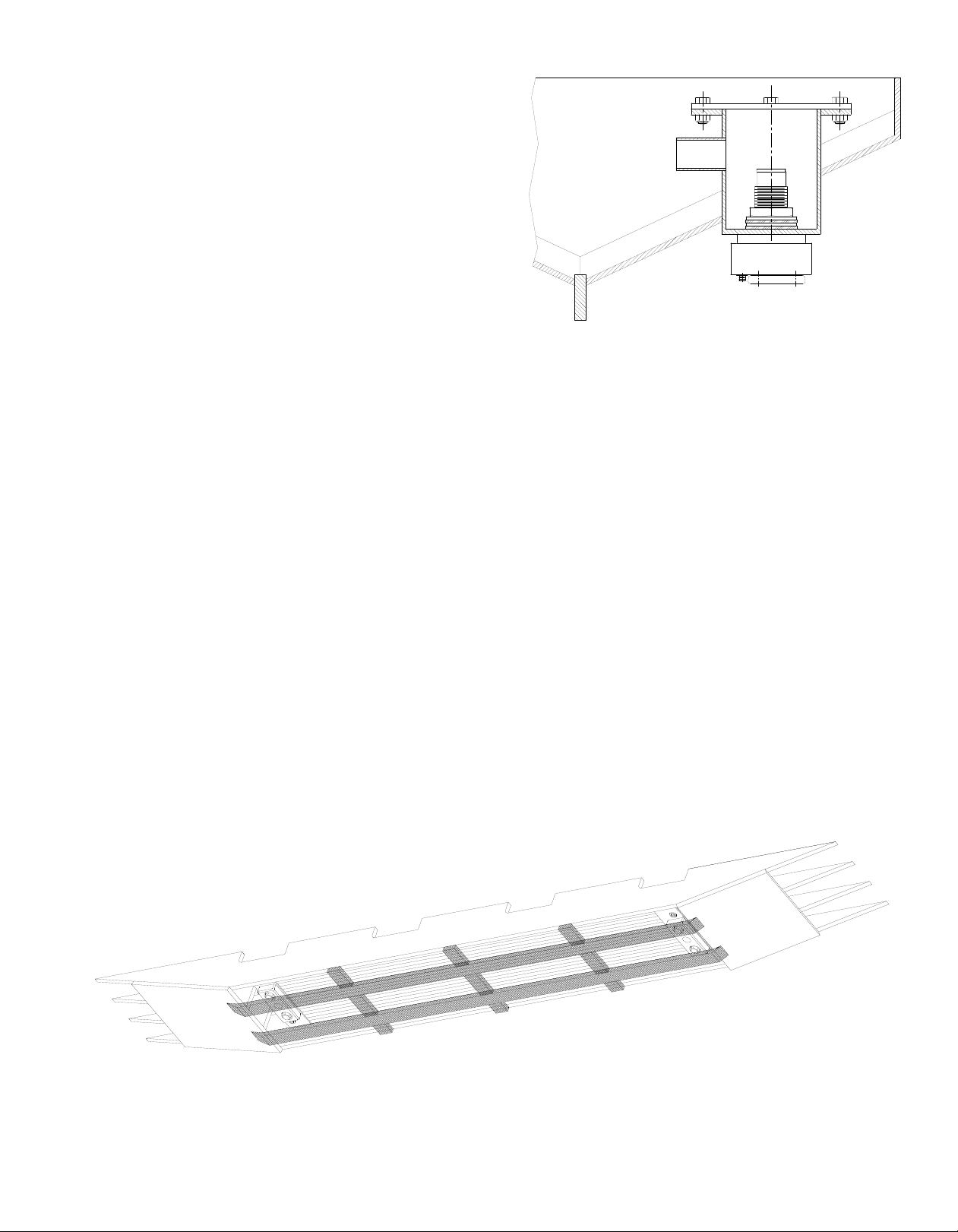
1.1.2 Always install the unit parallel, not transverse, to the
skeg or keel. See Figures 1 & 2.
FIG.1 External type installation with E1 OPTION
end-mounted anodes using fairing blocks for
protection and streamlining.
FIG.2 Recess type installation with E1 OPTION end-
mounted anodes.
1.1.3 When using a two-circuit cooling system, consisting
of a high temperature jacketwater circuit and a low
temperature aftercooler circuit, make certain the
aftercooler circuit cooler is placed forward of the
jacketwater circuit cooler. When room allows, they
can be installed side by side with the aftercooler
circuit lower on the hull (i.e. closer to the skeg or
keel) and a divider plate between the high and low
temperature units.
1.1.4 When the GRIDCOOLER unit is used on a generator
set or if your application requires sizing for a hull
speed of 0 knots, make sure that sea water can
freely circulate past the cooler tubes. Do not recess
a generator set unit on the bottom of a flat bottom
boat unless the hull section where the unit will be
mounted inclines a minimum of 20 degrees (from
forward to aft) to avoid entrapment of heated water
around the tubes. See Figure 3.
1.2 DETERMINING PROPER LOCATION –
DISPLACEMENT VESSELS
1.2.1 On vessels performing pushing, towing, dragging
or pulling operations, the unit may be installed near
the propeller, but not directly above it. See Figure 3.
Install the unit to avoid the full impact of the propeller
wash as this could cause damage to the unit.
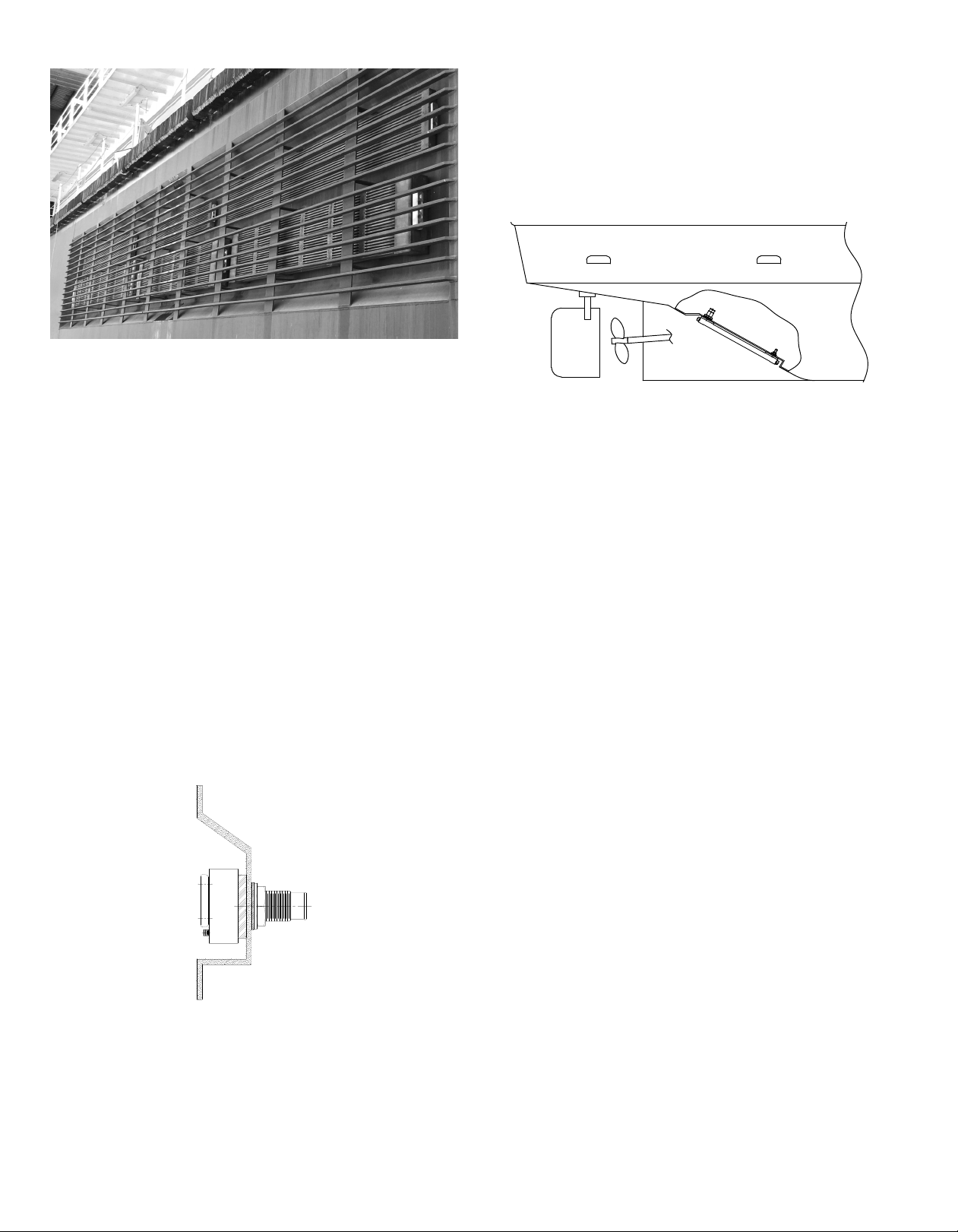
FIG.3 Recessed installation is made by welding in
a box-shaped recess in the hull. Note aft end
of recess is tapered to prevent hot water
entrapment.
1.2.2 When installing a unit on the side of a hull, position
it well below the water line to avoid aerated surface
water. Take the bow wave into consideration. Aeration
reduces heat transfer and can cause overheating.
Installation and Maintenance Manual form 185 Page 3
1.3 DETERMINING PROPER LOCATION –
PLANING VESSELS
1.3.1 For planing hull vessels, locate the unit as far aft as
possible to avoid aeration and impact shock in heavy
seas.
1.4 IMPROPER (NOT RECOMMENDED)
LOCATIONS
1.4.1 The area of the hull where the GRIDCOOLER® Keel
Cooler is installed must not vibrate or flex severely.
1.4.2 To eliminate unnecessary stress and vibration on the
cooler, do not locate the unit directly below engine
mounts or above the propeller(s).
1.4.3 Make sure that hot water is not discharged on or
near the unit.
1.4.4 Do not locate the unit on the front 1/3 of the hull for
displacement hulls. Bowthruster coolers could be an
exception, depending on the vessel.
1.4.5 The GRIDCOOLER Keel Cooler is designed to be
mounted directly to the hull. Do not mount the unit
to any external structure without first consulting the
factory.
1.5 MOUNTING CONSIDERATIONS – TYPICAL
1.5.1 Some classed vessels (ABS or Coast Guard, for
example) may require coerdams, check with your
local ocials for more information. For this type of
installation, see Coerdam Installation in Section 3.1.
1.5.2 The GRIDCOOLER unit can be canted from the hull
(sideways) to vertically align the nozzles. This can
reduce interference problems with stringers on
coerdam installations. See Figure 4. (referred to
section 3.1 for coerdam installation)
FIG.4 Canted Installation with Coerdam.
1.5.3 If the unit is recessed into the hull, make sure that
there is 1-1/2 in. (38 mm) minimum clearance on all
sides (this does not include between the hull and the
top of the cooler). The recess should be no deeper
than 1/2 in. (13 mm) plus the hull projection (listed on
installation drawing) of the cooler.
1.5.4 In extreme cases, where logs, debris, or dragging
bottom may endanger the unit, a protective guard
may be mounted over the unit. Make certain the
guard does not cover more than 25% of the face
opening. For examples of protective guards and
dierent installations that have been used, see
Figures 5 and 6.
FIG.5 Example of external guarding
Page 4 Installation and Maintenance Manual form 185
FIG.6 Side mounted coolers
1.5.5 Copper-nickel units can be bent to conform to
the hull. The bending can be done at the yard or
by R. W. Fernstrum & Company. Contact us if you
are considering bending a unit. See Section 4.1 –
Bending A GRIDCOOLER® Keel Cooler. The bending
of aluminum keel coolers is not recommended.
1.6 MOUNTING CONSIDERATIONS –
DISPLACEMENT VESSELS
1.6.1 Owners of vessels with displacement hulls moving
at less than 10 knots may find an external mounting
with fairing blocks to their advantage; provided
there isn’t much chance of the unit being damaged
in their operating environment
1.6.2 When recessing the unit into the side of the hull
for generator sets and/or equipment operating at
dockside, angle the top of the recess box to improve
convection current over the cooler. See Figure 7.
FIG.7 Side Mounted Recess.
NOTE: Recess box with angled top suggested for
generator set and equipment operating at
dock side only. NOT required for propulsion
engines.
1.6.3 When installing a multiple-pass unit on an incline,
make sure that the nozzles are at the high end to
avoid air entrapment. See Figure 8.
1.6.4 If coolers must be installed with the nozzles at the
low end, special units can be ordered with additional
vents in the stud end of the cooler.
FIG.8 U-Flow unit with E1 OPTION end mounted
anodes mounted on rake of vessel with
nozzles positioned to avoid air entrapment.
1.6.5 If side plates and fairing blocks are used, make sure
that the side plates are scalloped (notched) out so
they will not entrap water. Fairing blocks are most
eective when installed with a 4 to 1 slope. See
Figures 1 & 5.
1.7 MOUNTING CONSIDERATIONS – PLANING
VESSELS
1.7.1 We recommend using a recess on planing hulls and
vessels moving at 10 or more knots.
1.7.2 High speed applications (10+ knots) can reduce the
1-1/2 in. clearance recommendation in section 1.5.3
to 1/2 in. minimum due to increased raw water flow
over the cooler at high speed.
1.7.3 High speed applications and others that use E1
OPTION™ coolers should take into consideration the
removal and replacement of anodes and drain plugs
when sizing the length of a recess. See Figure 2.
1.8 BONDING OR ISOLATION TO MINIMIZE
CORROSION
1.8.1 It is recommended that the installer consult with a
corrosion engineer to review the corrosion protection
system of the vessel to determine the best mode of
installation for their particular situation.
1.8.2 Typically, it is common practice to isolate the keel
cooler from the hull. This ensures that the antifouling
property of the copper-nickel is at full potential.
However, there are other variables that may aect
the decision whether to isolate or bond the unit.

Installation and Maintenance Manual form 185 Page 5
2.0 INSTALLATION
Once you have decided on the correct location, use
the following steps as a guideline for installing your
GRIDCOOLER® Keel Cooler.
2.1 MAKING HOLES
2.1.1 Measure the distance between the inlet & outlet
nozzles from center to center (also measure to the
centers of the support studs when applicable) before
cutting holes for them in the ship’s hull.
2.1.2 Make the holes through the hull 1/4 in. (6.4 mm)
diameter oversized.
2.1.3 Make sure that the hull surfaces where the unit will
be mounted are smooth and properly aligned (on
steel hulls, if you burn the holes, grind the edges
smooth afterwards). This will allow the gaskets to
seal properly and ensure that no undue stress will be
placed on the cooler.
2.2 FITTING UP
2.2.1 Under normal conditions, the compression of the
mounting gaskets puts sucient tension on the
nozzle nuts (and support bolt nuts when applicable)
to prevent them from working loose. To seal out
water, apply a bead of sealant to the exterior of the
gaskets, and around the points where the nozzles
and support bolts penetrate the hull before assembly.
2.2.2 Remember to tighten the nuts again, after the
caulking has set.
2.3 COPPER-NICKEL INSTALLATION
2.3.1 Mounting gaskets supplied with the GRIDCOOLER
Keel Cooler must be used to provide proper spacing
between the unit and the ship’s hull. See Figure 9.
For exterior gasket thickness see the chart below, all
exterior gaskets are available in ¼” on request
NOTE: INSULATORS: Insulators for galvanic isolation
of through-hull installation studs and nozzles
are available upon request at time of purchase.
When requesting the insulators, provide hull
thickness so the insulators can be supplied at
the proper length.
FIG.9 Mounting Parts Placement
NOTE: IF CONCAVE WASHERS ARE
USED, MAKE SURE CONCAVE SIDE
IS DOWN ON GASKET. FOR NIPPLE
WASHERS THAT ARE CAST, PLACE THE
ROUGH SIDE AGAINST THE GASKET.
EXTERIOR GASKET THICKNESS
B
¼”
6.4mm ½”
12.7mm ¼”
6.4mm
½”
12.7mm
BN C CN D
¾”
19mm

Page 6 Installation and Maintenance Manual form 185
2.3.2 To avoid over-tightening any of the supporting nuts,
we recommend the following torques for all standard
installations:
2.3.3 Anodes are standard equipment with copper-nickel
units. They minimize the eects of galvanic corrosion
and should be replaced when deteriorated. The life
of these plates varies with localities.
2.3.4 Attach the anodes using the special bolts and
washers supplied with the unit. They can be found
in a cardboard box inside the unit shipping box. See
Figure 10.
FIG.10 Anode Attachment Detail
NOTE: Anode replacement kits, including anodes,
screws, and washers, can be ordered from
the factory. They are available with zinc
anodes or aluminum anodes upon request.
Please provide the model number of your
GRIDCOOLER® Keel Cooler to ensure the
proper replacement anodes are sent.
2.4 ALUMINUM INSTALLATIONS
2.4.1 Aluminum GRIDCOOLER Keel Coolers should be
installed on unpainted aluminum hulls only.
2.4.2 The 1/4-inch mounting gaskets supplied with the unit
must be used to provide proper spacing between
the cooler and the ship’s hull.
2.4.3 To avoid over-tightening any of the supporting nuts,
we recommend the following torques for all normal
installations:
2.4.4 Most aluminum units have tapered threads on the
nipples and no hose connectors (see installation
drawing). These units can be piped directly to the
engine, provided flexible couplings are used to
remove engine vibration between the engine and
the cooler.
2.4.5 If a wire reinforced rubber hose is used to connect
the unit to the engine, put a screw-on coupling over
the cooler nozzle threads.
2.4.6 Aluminum GRIDCOOLER Keel Coolers do not use
anodes.
2.5 PLUMBING
NOTE: Prior to installing cooler, flush entire piping
system to remove any debris.
2.5.1 Remove the orange nozzle plugs from the
GRIDCOOLER unit before hooking up the plumbing
to the cooler.
2.5.2 Engines equipped with inboard raw water heat
exchangers may not be able to be converted to
keel cooling, please consult your engine dealer and
Fernstrum representative for guidance.
2.5.3 As a rule-of-thumb, the expansion tank for your
cooling system should be able to hold approximately
COPPER-NICKEL UNIT
NUT TORQUES FT.-LBS. (KG-M)
NOZZLE THREAD SIZE
¾”
19mm
50 - 60
(7 - 8)
HEADER STUD SUPPORT BOLT
1 - 1 ½”
25 - 38mm
75 - 100
(10 - 14)
2”
51 mm
125 - 150
(17 - 21)
2 ½ - 3 ½”
63 - 89mm
200 - 250
(28 - 35)
⅝ - ¾”
16 - 19mm
35 - 40
(5 - 5 ½)
1”
25 mm
50 - 60
(7 - 8)
½ - ¾”
13 - 19mm
20 - 25
(3 - 3 ½)
ALUMINUM UNIT
NUT TORQUES FT-LBS (KG-M)
NOZZLE THREAD
1 ½ - 3”
38 - 76mm
125 - 150
(17 - 21)
⅝”
16mm
20 - 25
(3 - 3 ½)
1”
25 mm
75 - 100
(10 - 14)
SUPPORT BOLT

Installation and Maintenance Manual form 185 Page 7
10% of the total cooling system coolant. Contact
your engine dealer for the exact size.
2.5.4 When piping, do not use tubing or fittings smaller
than the engine or keel cooler connections. If those
on the engine are larger than those on the keel cooler,
reduce the piping at the keel cooler, not the engine.
Use a minimum of elbows and check all connections
for leaks. All high areas in piping must be vented.
2.5.5 To avoid transmitting engine vibrations to the
GRIDCOOLER unit, use wire reinforced rubber
hoses and clamps at the engine and keel cooler
connections.
2.5.6 When installing a multiple-pass unit in a side mounted
position, the inlet line should be connected to the
lower nozzle to force air up and out of the cooling
system. Special units can be ordered with additional
air bleeding vents in the stud end of the cooler.
2.5.7 To avoid air pockets that would restrict coolant flow
through the system and cause overheating, install
the piping between the engine and the cooler so
that it is self- venting.
NOTE: Depending on installation, special air bleeding
vents are available as an option.
2.5.8 For piping diagrams for multiple cooler installations,
see Figures 11 through 14.
FIG.11 Coolers connected in parallel
FIG.12 Multiple-pass coolers connected in parallel
FIG.13 Coolers connected in series
FIG.14 Coolers connected in series parallel
2.6 FILLING & TESTING
NOTE: Do not exceed 35 PSI (2.41 Bar) when pressure
testing a GRIDCOOLER® Keel Cooler.
2.6.1 Always premix ethylene glycol (antifreeze) with
water before adding it to the cooling system. Contact
your engine dealer for the proper antifreeze type and
percentage for your engine. We do not recommend
the use of propylene glycol in your cooling system.
2.6.2 Never mix ethylene and proplyene glycol-based
antifreezes in your cooling system.
2.6.3 When installing a GRIDCOOLER Keel Cooler in a
side mounted position, it is important that the unit
is completely filled with coolant before launching
the vessel. This can be accomplished by using the
following procedure:
2.6.4 At the outlet end of the unit, remove the upper drain
plug and fill the unit with coolant
2.6.5 When coolant runs out of the upper drain, replace
the plug.
2.6.6 The unit is now filled with coolant. If the system is
ever drained, you must repeat this procedure.

Page 8 Installation and Maintenance Manual form 185
3.0 SPECIAL INSTALLATIONS
3.1 COFFERDAM INSTALLATION WITH
COMPRESSION SEALING KIT
3.1.1 Place a continuous bead of sealant around the
header gasket that separates the GRIDCOOLER®
unit from the outer hull. Customers have reported
good success with polysulfide rubber sealants.
3.1.2 Place a second continuous bead of sealant on the
inner hull around the nipple. This bead must be in
contact with the hull and the nipple.
3.1.3 Hoist the unit up into the mounting position. The
exterior header gasket must be in full contact with
the hull.
3.1.4 Place the nipple gasket (harder of the two interior
gaskets) down over the nozzle as far as possible.
3.1.5 Place the unfinished cast washer down over the
nipple as far as possible. The side of the washer
marked “up” must face away from the hull.
3.1.6 Place the compression gasket (softer of the two
interior gaskets) down over the nipple as far as
possible.
3.1.7 Place the semi-finished washer down over the nipple,
finished side away from the hull.
3.1.8 Run the nut down over the nipple and torque to
spec. (See chart in Section 2.3.2)
3.1.9 Torque the nut to spec a second time after the
sealant has set.
FIG.15 Compression Sealing Parts Replacement

Installation and Maintenance Manual form 185 Page 9
OPTION: For ease of installation and maintenance,
pipe to the side of the coerdams. (see Figure
16)
FIG.16 Pipe to side of coerdam
3.2 Z OPTION™ INSTALLATIONS
3.2.1 The Z OPTION GRIDCOOLER Keel Cooler replaces
the standard through-hull nozzle mounting/
connecting means with a copper-nickel flange,
fused to the header. This flange utilizes a plurality of
stainless-steel mounting studs locked in place by set
screws to allow replacement in the event of damage.
3.2.2 The unit is also supplied with mating ASTM steel
flanges and flange mounting hardware. The supplied
hardware illustrated in Figure 17 includes nylon
shoulder washers combined with neoprene gaskets
to allow isolation from the vessel’s hull. Special extra
heavy lock nuts and washers are provided for a
secure installation.
3.2.3 Flange mounting hardware can be found in a
cardboard box inside the unit shipping box.
3.2.4 The mating steel flange is welded to a pipe stub
extending from the hull of the vessel. This pipe stub
must be long enough to allow access to the flange
lock nuts for tightening. Alignment of the flanges
on the hull is critical. We suggest that a template be
made of the cooler to aid with the proper alignment
of the flanges.
NOTE: Temporarily remove nylon shoulder washers
while welding. Re-insert prior to mounting
cooler
The torque specification for the flange nuts is as follows:
NOTE: Z OPTION units utilize our L OPTION™ support
plates for intermediate mounting of the cooler.
See the next section for L OPTION mounting
instructions.
FLANGE NUT TORQUE SPECIFICATIONS
⅝” diameter or
larger stud
35 - 40 FT. LBS.
½” diameter stud
20 - 25 FT. LBS.
FIG.17 Z OPTION mounting detail

Page 10 Installation and Maintenance Manual form 185
3.3 L OPTION™ SUPPORT PLATE INSTALLATION
The L OPTION support plates do not require a through-hull
penetration. These support plates extend beyond the sides
of the keel cooler allowing the customer the option to weld
a mounting stud directly to the hull or to weld a short piece
of angle to the hull as a securing means. The customer can
then install the appropriate fasteners for the support plates.
Figures 18 and 19 show examples of this style of mounting.
The combination of the neoprene gasket and the nylon
shoulder washer provide isolation of the cooler from the hull.
NOTE: Do not cut o the center stud on your
GRIDCOOLER® Keel Cooler. The center stud is
there to provide necessary support for your
keel cooler when it is attached to the hull.
FIG.18 L OPTION support plate with stud welded to hull
FIG.19 L OPTION support plate with angle welded to hull

Installation and Maintenance Manual form 185 Page 11
3.4 MOUNTING COPPER-NICKEL COOLERS ON
ALUMINUM HULLS
3.4.1 An electrical barrier must be placed between the
GRIDCOOLER® unit and the hull. R. W. Fernstrum &
Company does not formally approve any method of
installing a copper-nickel GRIDCOOLER Keel Cooler
on unpainted aluminum hulled vessels. However, the
following technique has been used on hundreds of
boats.
3.4.2 Sandblast the area of the hull where the unit will be
installed.
3.4.3 Coat the sandblasted area with a two-part fiberglass
epoxy resin.
3.4.4 Spray the resin on in four separate coats. Do not use
any matting. Spray each coat just heavy enough so
that it does not start to run o.
3.4.5 After spraying on the fourth coat, and while the
resin is still tacky, prime the entire area with the hull
priming paint used on the rest of the vessel’s hull.
3.4.6 Apply the final bottom paint, and then install the
cooler.
Page 12 Installation and Maintenance Manual form 185
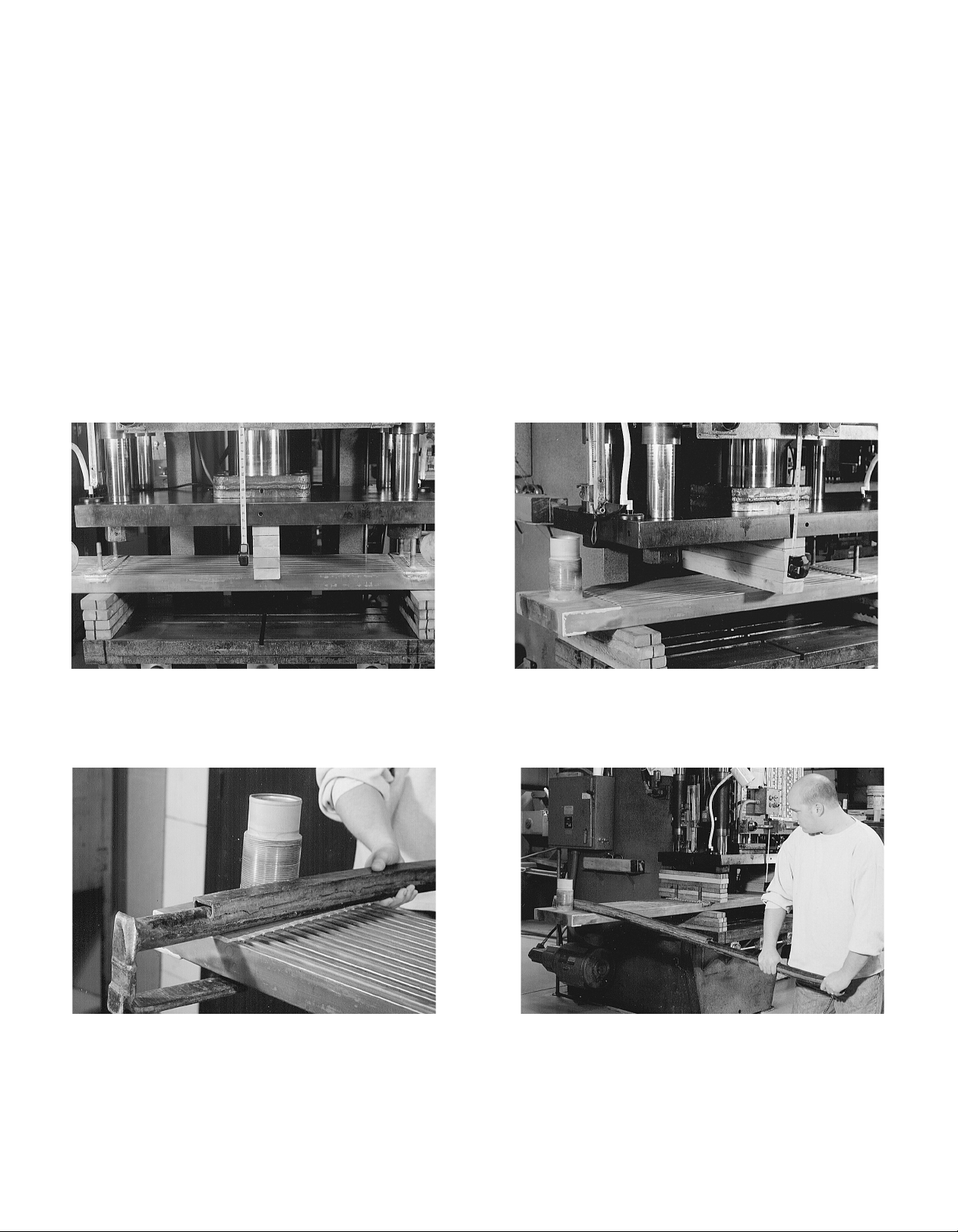
4.0 FORMING THE GRIDCOOLER® KEEL COOLER
BENDING A GRIDCOOLER KEEL COOLER
When bending a cooler in a press, support the cooler from
underneath with wood blocking across the entire width of
the unit. Blocking is also placed on top of the cooler, centrally
located between the wood blocking underneath the cooler.
The location of the wood blocking on the top of the cooler
will determine the location of the bend. Since this method
of bending exerts pressure on only a small area, the cooler
will need to be repositioned multiple times to produce an
even bend over the length of the cooler. Care must be taken
to ensure that the unit is not bent too far at any one point.
A tape measure or other measuring instrument, along with
a template of the hull profile can be used to measure your
progress. See Figures 20 and 21.
TWISTING A GRIDCOOLER KEEL COOLER
To produce a twist, first fabricate a hook onto the end of a
short length of pipe using barstock. Hook this bar across the
header as close to the nipple or stud as possible. The cooler
may be secured in a press or placed on sawhorses with a
person at each end. By placing your weight on the end of
the pipe, you can produce a twist in the cooler. See Figures
22 and 23.
NOTE: Do Not Bend greater than 1” (25 mm) over
12” (305 mm) of cooler length. Do Not Twist
beyond 1° over 12” (305 mm) of cooler length.
Do Not Tension Bend the keel cooler.
FIG.20 Creating a bend in a cooler using a
hydraulic press
FIG.21 Creating a bend in a cooler using a
hydraulic press
FIG.23 Carefully apply downward force to
impart a twist in the cooler
FIG.22 Locate twisting hook as close as
possible to the nozzle or stud

Installation and Maintenance Manual form 185 Page 13
5.0 PERFORMANCE ISSUES
Determining the cause of overheating can be dicult. Here
are some things to look for:
WIRE REINFORCED RUBBER HOSE:
Could the rubber hose connecting the engine piping and the
cooler be collapsed? This could cut the cooling water supply
to the unit and reduce its eciency. Be sure you are using
wire reinforced rubber hose.
PIPING:
Is the piping between the engine and the cooler as large or
larger than the engine and cooler connections? (See section
2.5.4 under plumbing.) The piping should also be self-venting
and arranged so that a minimum number of elbows are used.
JACKETWATER:
Is the coolant circulating through the cooler? It may be taking
a path of least resistance through the bypass (if one exists).
THERMOSTAT:
Could the thermostat be stuck, or could the wrong thermostat
be in use? If so, it could give you a faulty temperature.
CIRCULATING PUMP:
Is the circulating pump working properly? If not, it could
reduce the cooling systems eciency.
AIR IN THE SYSTEM:
Was the unit installed in a way to allow all the air in the system
to escape? When a multiple-pass unit is mounted on the rake
of the vessel, make sure that the nozzles are mounted in the
up or high position. See sections 1.6.3, 2.5.6, 2.5.7, & 2.6.3
under Installation. See Figure 8
FOREIGN MATTER:
Could anything have gotten into the cooler nozzles? Make
sure that the orange plastic cap plugs covering the ends
of the hose connectors were removed and that no foreign
matter, such as a rag, was dropped into the cooler nozzles.
EXPANSION TANK:
Could the water level be too low in the expansion tank? This
can reduce the cooling system’s eciency.
EXTERNAL COATING:
Is the cooler painted or covered with any other coating? This
will have an insulating eect and will greatly reduce the heat
transfer rate of the unit. The standard recommendation is to
not coat the keel cooler.
WATER AERATION:
Could the water around the cooler be aerated in any way?
Aeration will reduce the heat transfer rate of the keel cooler.
MOORED AT DOCK:
Is the engine temperature rising while the vessel is moored
in dock? If the unit is installed near the propeller, engage
the propeller to circulate water past the unit, after taking the
proper safety precautions.
PLACEMENT:
Is an aftercooler circuit overheating? Make sure that the low
temperature cooling circuit is mounted forward of or closer
to the skeg or keel than the jacketwater coolers.
MOUNTING GASKETS:
Were the mounting gaskets put in place when the unit was
installed? The mounting gaskets supplied with the cooler
must be used to provide adequate spacing between the unit
and the ship’s hull. This will allow water to flow freely over
the cooler tubes.
GLYCOL:
How much glycol (antifreeze) is in the system? Perhaps the
cooler was not sized for the use of glycol in the system.
NOTE: Always premix glycol with water before adding
it to the cooling system.
NOTE: Never mix ethylene and propolyene glycol.
CRUSHED TUBES:
Have the rectangular tubes on the cooler been crushed or
pinched? This could restrict the internal water flow.
BLOWN TUBES:
Could the rectangular tubes on the unit have been blown or
bulged by unusually high pressures? If so, the exterior water
flow past the unit tubes could be impaired, retarding heat
transfer.
MARINE GROWTH:
Has your vessel been in dock for several months? You may
find marine growth on the unit which will hinder the unit’s
heat transfer rate. See Maintenance Section.
OIL DEPOSITS:
Have you had engine problems? Oil may have gotten into the
cooling water system and collected in the cooler, coating it
with an oil film. See Maintenance Section.
MINERAL DEPOSITS:
Could you be using hard water in the system? Mineral
Deposits can collect on the tube in the cooler, lining the
inside with lime, calcium, etc. See Maintenance Section.

Page 14 Installation and Maintenance Manual form 185
6.0 MAINTENANCE
A GRIDCOOLER® Keel Cooler that is clean inside and out
will dissipate heat most eciently. To keep your unit clean, a
periodic check of the cooling system is recommended. What
follows are some ways to clean your GRIDCOOLER unit.
EXTERIOR
If the GRIDCOOLER Keel Cooler is used regularly, the 90/10
copper-nickel alloy in conjunction with the unit’s operating
temperature will tend to keep the exterior of the unit
relatively free of marine growth. However, if the unit is not in
operation for extended periods of time, marine growth may
result. Below are some ways of removing marine growth,
paint, etc. from the exterior of the GRIDCOOLER unit:
SCRAPE:
Scraping is an eective way of removing larger matter from a
cooler. The use of a rectangular instrument works best.
PRESSURE WASHING:
Pressure washing is eective in cleaning many things o of a
cooler. Do not exceed 3000 psi (206.84 bar).
SANDBLAST:
Sandblasting is also very eective, but very fine sand such as
40 to 60 grit blasting media should be used.
For suction blast do not exceed 90 psi (6.21 bar).
For pressure pot blasting do not exceed 35 psi (2.41 bar).
NOTE: Never sandblast an ALUMINUM GRIDCOOLER
unit.
PAINTING:
Coolers do not require painting. Doing so will decrease the
unit’s eciency.
ANODES:
Anodes are standard equipment with most copper-nickel
units. They minimize the eects of galvanic corrosion and
should be replaced when deteriorated. The life of these
anodes varies with localities.
Anode replacement kits, including anodes, screws, and
washers, can be ordered from the factory. When contacting
our sales representatives, provide the model number of your
GRIDCOOLER Keel Cooler. Anodes are available in aluminum
or zinc material.
NOTE: Anodes installed on coolers provide immediate
protection to the cooler only. When using an
active protective system, the cooler should be
taken into consideration during the hull survey.
INTERIOR
The interior of your GRIDCOOLER unit may need periodic
cleaning to remove oil, old glycol, mineral deposits, etc. The
easiest and most convenient way of doing this is the use of
a radiator flush. Contact your engine dealer for the proper
radiator flush type for your engine.
PRESSURE TESTING
Do not exceed 35 psi (2.41 bar) when pressure testing a
GRIDCOOLER® Keel Cooler.

Installation and Maintenance Manual form 185 Page 15
7.0 REPAIR
For a unit in warranty, attempt no repairs without first
contacting the manufacturer, otherwise your warranty will
be void.
For a unit out of warranty, if the unit is accidentally damaged
while in use, you can make minor shipyard repairs as follows:
STRAIGHTENING
If the tubes are accidentally bent, they can be straightened
with a hard wood block and a mallet. See Figure 24.
FIG.24 Straightening tubes with a wooden block &
mallet
COPPER-NICKEL GRIDCOOLER® KEEL COOLER
REPAIRS
BRAZING:
Drain the cooler before brazing. Clean the area or joint to be
brazed thoroughly with a good degreasing solvent followed
by wire brushing. The braze wire should be 56% silver, AWS
A5.8 BAg-7. See Figure 25.
FIG.25 Brazing repair
TIG WELDING:
C70600 copper-nickel or monel 67 wire may be used.
TEMPORARY REPAIR
For temporary repairs, liberally apply an epoxy compound.
Before applying the epoxy compound, clean the surface of
the GRIDCOOLER unit and relieve any internal pressure.
For major repairs not covered by our Limited Warranty,
contact us. Give us a complete description of the damage,
and we will tell you if and how your unit can be repaired.
TUBE COUPLING REPAIRS
A damaged section of D or C tube can be replaced with two
couplings and a replacement length of tube brazed in place.
FIG.26 Replacing a section of tube
A single coupling can be cut or split, slid over the tube, and
brazed into place to patch a hole in a tube.
FIG.27 Patching a hole in a tube
ALUMINUM GRIDCOOLER KEEL COOLER REPAIRS
TIG WELDING:
Drain the cooler before welding. Clean the area or joint to be
welded thoroughly with a good degreasing solvent followed
by stainless steel wire brushing. The aluminum filler rod used
in the GRIDCOOLER Keel Cooler is R 5554 aluminum wire.

Page 16 Installation and Maintenance Manual form 185
8.0 STRAY-CURRENT CORROSION
Since Fernstrum’s involvement in the design of any particular
marine vessel is limited to the heat transfer requirements of
the vessel, grounding or bonding of the keel cooler is best
left to the person responsible for the design of the corrosion
protection system. If the customer needs guidance on this
issue it is suggested to isolate the cooler from the hull and
monitor closely the condition of the cooler, anodes and
surrounding hull area for the first few months. This is for the
simple fact that it is easier to ground a cooler after installation
than it is to isolate it.
When welding is taking place on the hull while in the water,
steps should be taken to monitor the keel cooler for any
possible stray current corrosion. For guidance on proper
welding equipment connections for waterborne vessels,
we suggest consulting either NAVSEA S9086-CH-STM-010/
CH-074R4 Welding and Allied Processes, Naval Ships’
Technical Manual Chapter 74 - Volume 1, or ANSI/AWS
D3.5:1993(R2000) Guide for Steel Hull Welding, Section 6
Stray Current Protection. Note that the Section 6 of the ANSI/
AWS D3.5:1993 standard comes directly from the document
provided by NAVSEA.
If an impressed current system is used, it is best to consult
the manufacturer of the system for their recommendations
as to grounding or bonding of equipment mounted to the
hull.
The product warranty is not aected by how the keel cooler
is configured into the corrosion protection system, as it
covers defects in material and workmanship, not failure due
to galvanic or stray current corrosion.
The best plan of action is to have a corrosion engineer
evaluate the corrosion protection scheme of the vessel and
verify its proper function.
Installation and Maintenance Manual form 185 Page 17
9.0 REPLACEMENT PARTS
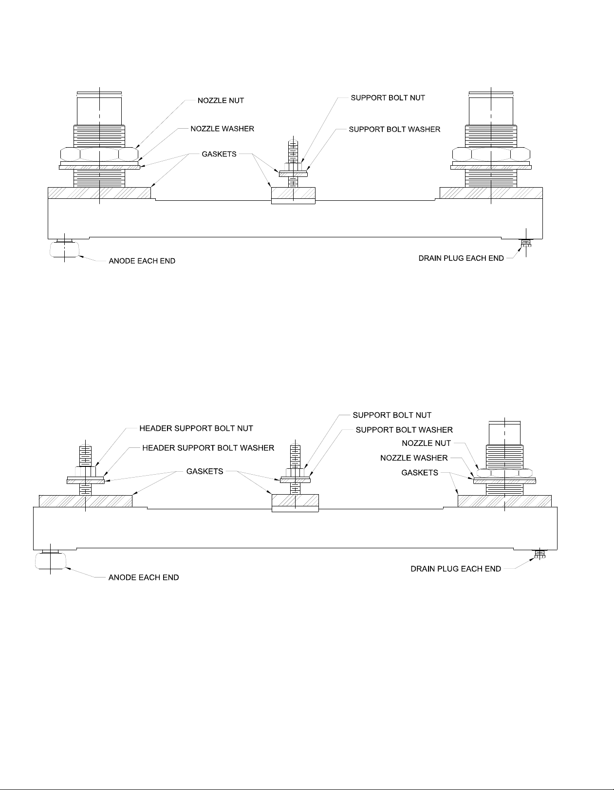
FIG.28 Single Pass Gridcooler Keel Cooler
FIG.29 Multi Pass Gridcooler Keel Cooler

Page 18 Installation and Maintenance Manual form 185
FIG.30 Z-Option Single Pass Gridcooler Keel Cooler
FIG.31 Z-Option Multi Pass Gridcooler Keel Cooler
NOTE: All gaskets are sold in complete sets. Gasket
sets include all internal gaskets, exterior
gaskets and isolators.
NOTE: Anodes are sold in kits consisting of anodes
and mounting hardware. Most Keel Coolers
require one (1) anode kit. Larger Keel Coolers
may require two (2) anode kits. Keel Cooler
model number is needed to identify correct
kit. Anodes are standardly sold in zinc, but
can be aluminum upon request.
9.0 REPLACEMENT PARTS
Table of contents
Popular Accessories manuals by other brands

PCB Piezotronics
PCB Piezotronics 113B03 Installation and operating manual

Omron
Omron E3T-C datasheet

MIXX CHARGE
MIXX CHARGE Powerlife C10 quick start guide

BEA
BEA ACTIV8 THREE F instructions

TEKTELIC Communications
TEKTELIC Communications T0005982 user guide

Siemens
Siemens SITRANS CU02 operating instructions

IFM
IFM UIT510 operating instructions

EVA Logik
EVA Logik ZW39 installation manual

Weil-McLain
Weil-McLain Gold GV 2 Series Replacement instructions

Ace
Ace Lighted Wireless Push Button Accessory... owner's manual

Galvin Engineering
Galvin Engineering CliniMix CMV2 Product installation guideline
 Specifications")
Panasonic
Panasonic MA2J114 (MA114) Specifications


