TEKTELIC Communications T0005982 User manual

PROPRIETARY:
The information contained in this document is the property of TEKTELIC Communications Inc. Except as specifically
authorized in writing by TEKTELIC, the holder of this document shall keep all information contained herein
confidential, and shall protect the same in whole or in part from disclosure to all third parties.
© 2019 TEKTELIC Communications Inc., all rights reserved.
All products, names, and services are trademarks and registered trademarks of their respective companies.
TEKTELIC Communications Inc.
7657 10th Street NE
Calgary, AB, Canada T2E 8X2
Phone: (403) 338-6900
LORA IOTAGRICULTURE SENSOR
User Guide
Document Type: User Guide
Document Number: T0005978_UG
Document Version: 1.9
Product Name: Agriculture Sensor
Product Code: T0005982 (Agriculture Sensor, Soil Surface Mount Module, NA)
T0005983 (Agriculture Sensor, Soil Surface Mount Module, EU)
T0005986 (Agriculture Sensor, Elevated Mount Module, NA)
T0005987 (Agriculture Sensor, Elevated Mount Module, EU)
Issue Date: April 5, 2021

LoRa Agriculture Sensor User Guide T0005978_UG Version # 1.9
TEKTELIC Communications Inc. Confidential Page 2 of 22
Document Revision
Revision
Issue Date
Status
Editor
Comments
0.1
June 4, 2019
Initial Draft
Emma Tholl
First draft.
0.2
January 28, 2020
Draft
Mark Oevering
Numerous updates
Updated part numbers in
Table 1.
0.3
April 6, 2020
Release
candidate
Mark Oevering
Updated document to new
template.
Update to Compliance
statement.
1.0
April 16, 2020
Release
Mark Oevering
Changes to naming
convention for modules.
1.1
April 16, 2020
Release
Conor Karperien
Updated table for default
configuration.
1.2
April 20, 2020
Release
Mark Oevering
Added note about using the
sensor in direct sunlight.
Changed default
configuration in Tables 3 &
4 as a result.
Added more detail about
how soil moisture is
measured between the two
modules.
1.3
May 14, 2020
Release
Mark Oevering
Refined statement about
direct sunlight in overview
section.
Change to magnetic wake-
up pattern.
1.4
May 27, 2020
Release
Zenon Herasymiuk
Added battery polarity
statement on Section 1.3
1.5
July 7, 2020
Release
Mark Oevering
Added Watermark
information in Overview
section
1.6
July 22, 2020
Release
Mark Oevering
Clarifications to table for
Figure 3, Page 9
1.7
September 28, 2020
Release
Mark Oevering
Added note regarding tape
over battery for early
versions of the Agriculture
Sensor
1.8
December 16, 2020
Release
Mark Oevering
Corrections to Table 2
1.9
April 5, 2021
Release
Mark Oevering
Added ALS range to Table 2

LoRa Agriculture Sensor User Guide T0005978_UG Version # 1.9
TEKTELIC Communications Inc. Confidential Page 3 of 22
Table of Contents
1 Product Description ..................................................................................................................... 6
1.1 Overview .......................................................................................................................... 6
1.2 Physical Interfaces............................................................................................................ 9
1.3 Specifications.................................................................................................................. 10
2Installation............................................................................................................................. 12
2.1 Included Product and Installation Material ................................................................... 12
2.2 Safety Precautions.......................................................................................................... 12
2.3 Unpacking and Inspection.............................................................................................. 12
2.4 Equipment Required for Installation.............................................................................. 12
2.5 Elevated Mount Sensor Mounting................................................................................. 13
2.6 Cable Installation............................................................................................................ 13
3Power Up, Commissioning and Monitoring .......................................................................... 15
3.1 Reed Switch Awakening Procedure ............................................................................... 15
3.2 Commissioning ............................................................................................................... 17
4Battery Replacement............................................................................................................. 18
5Operation, Alarms, and Management................................................................................... 19
5.1 Configuration.................................................................................................................. 19
5.2 Default Configuration..................................................................................................... 19
5.3 LED Behaviour ................................................................................................................ 19
6Compliance Statements......................................................................................................... 21

LoRa Agriculture Sensor User Guide T0005978_UG Version # 1.9
TEKTELIC Communications Inc. Confidential Page 4 of 22
List of Tables
Table 1: Agriculture LoRa IoT Sensor Models ................................................................................. 6
Table 2: Agriculture Sensor Specifications.................................................................................... 10
Table 3: Default Configuration - Soil Surface Mount.................................................................... 19
Table 4: Default Configuration - Elevated Mount......................................................................... 19

LoRa Agriculture Sensor User Guide T0005978_UG Version # 1.9
TEKTELIC Communications Inc. Confidential Page 5 of 22
List of Figures
Figure 1 Agriculture Sensor Soil Surface Mount Model................................................................. 7
Figure 2 Agriculture Sensor Elevated Mount Model ..................................................................... 8
Figure 3 Agriculture Sensor Connector Block ................................................................................ 9
Figure 4 Mounting Holes.............................................................................................................. 13
Figure 5 Reed switch location...................................................................................................... 16
Figure 6 Agriculture Sensor magnetic reset/wake-up pattern.................................................... 16
Figure 7 Agriculture Sensor magnetic UL-triggering pattern....................................................... 17
Figure 8 LED Location................................................................................................................... 20

LoRa Agriculture Sensor User Guide T0005978_UG Version # 1.9
TEKTELIC Communications Inc. Confidential Page 6 of 22
1 Product Description
1.1 Overview
The Agricultural Sensor is a multi-purpose LoRaWAN IoT sensor intended for Agricultural use.
The Sensor supports up to four Analog and Digital inputs allowing for the remote capture of
data. The “Soil Surface Mount” model includes two metal probes; this addition uses two
inputs. Table 1 presents the Agriculture Sensor models. Without the probes the device
becomes the “Elevated Mount” model.
Table 1: Agriculture LoRa IoT Sensor Models
Product Code &
Revision
Description
RF Region
Tx Band
(MHz)
Rx Band
(MHz)
T0005986
AGRICULTURE SENSOR,
ELEVATED MOUNT
MODULE, NA
US 902-928
MHz (ISM
Band)
923-928
902-915
T0005987
AGRICULTURE SENSOR,
ELEVATED MOUNT
MODULE, EU
EU 863-870
MHz (ISM
Band)
863-870
863-870
T0005982
AGRICULTURE SENSOR,
SOIL SURFACE MOUNT
MODULE, NA
US 902-928
MHz (ISM
Band)
923-928
902-915
T0005983
AGRICULTURE SENSOR, SOIL
SURFACE MOUNT MODULE,
EU
EU 863-870
MHz (ISM
Band)
863-870
863-870
The main features of the Agricultural Sensor are the following:
Temperature & Relative Humidity Sensor: Reports temperature and relative humidity
of the local environment. PLEASE NOTE: PLACING THE UNIT IN DIRECT SUNLIGHT WILL
RESULT IN THE SENSOR REPORTING CASE TEMPERATURE AND RELATIVE HUMIDITY
INSTEAD OF TRUE AMBIENT CONDITIONS. PLACE THE UNIT OUT OF THE SUN FOR
MORE ACCURATE AMBIENT TEMPERATURE AND RELATIVE HUMIDITY READINGS.
Accelerometer: High sensitivity device that can measure any shock or movement
events. The primary purpose is to measure impact alarms.
Light Sensor: Reports the amount of light in the local environment.
Battery Gauge: Fuel gauges for non-rechargeable lithium batteries that can provide
accurate results with ultra-low average power consumption.
Watermark Sensor: Option to receive data on soil water tension. The Watermark is a
resistive device that responds to changes in soil moisture. Once planted in the soil, it
exchanges water with the surrounding soil thus staying in equilibrium with it. Soil water
LoRa Agriculture Sensor User Guide T0005978_UG Version # 1.9
TEKTELIC Communications Inc. Confidential Page 7 of 22
is an electrical conductor thereby providing a relative indication of the soil moisture
status. As the soil dries, water is removed from the sensor and the resistance
measurement increases. Conversely, when the soil is rewetted, the resistance lowers.
The relationship of ohms of resistance to centibars (cb) or kilopascals (kPa) of soil water
tension is constant. The Watermark is calibrated to report soil water tension or matric
potential, which is the best reference of how readily available soil water is to a plant.
The raw data reported by the sensor for the watermarks is a frequency that increases as
the watermark gets more saturated. Please refer to the TRM for information on how to
convert the frequency to Soil Water Tension.
It should be noted that Watermark sensors need to be installed wet. If time permits,
slowly wet the sensor by partially submerging (no more than half way) for 30 minutes
in the morning and let dry until evening, wet for 30 minutes, let dry overnight, wet
again for 30 minutes the next morning and let dry until evening. Soak over the next
night and install WET. This will improve the sensor response.
There are several things to note regarding installation depending on the use case for
the Watermark sensor. Please review “Sensor Installation” on Page 1 in the file “701
Meter Manual-WEB.pdf” file in the User Guide section of Agriculture Sensor in the
Knowledge Base of the Tektelic Support Portal.
Soil Surface Mount Probe: Option to measure soil moisture content and temperature.
The probes work in a similar manner to the Watermark Sensor described above. There
is no exchange of water with the surrounding soil, however. The probes simply measure
how saturated and warm or cold the soil is that they are inserted into. The raw data
provided by the sensor for soil moisture is a frequency. Please refer to the TRM for
information on how to convert the frequency to Gravimetric Water Content.
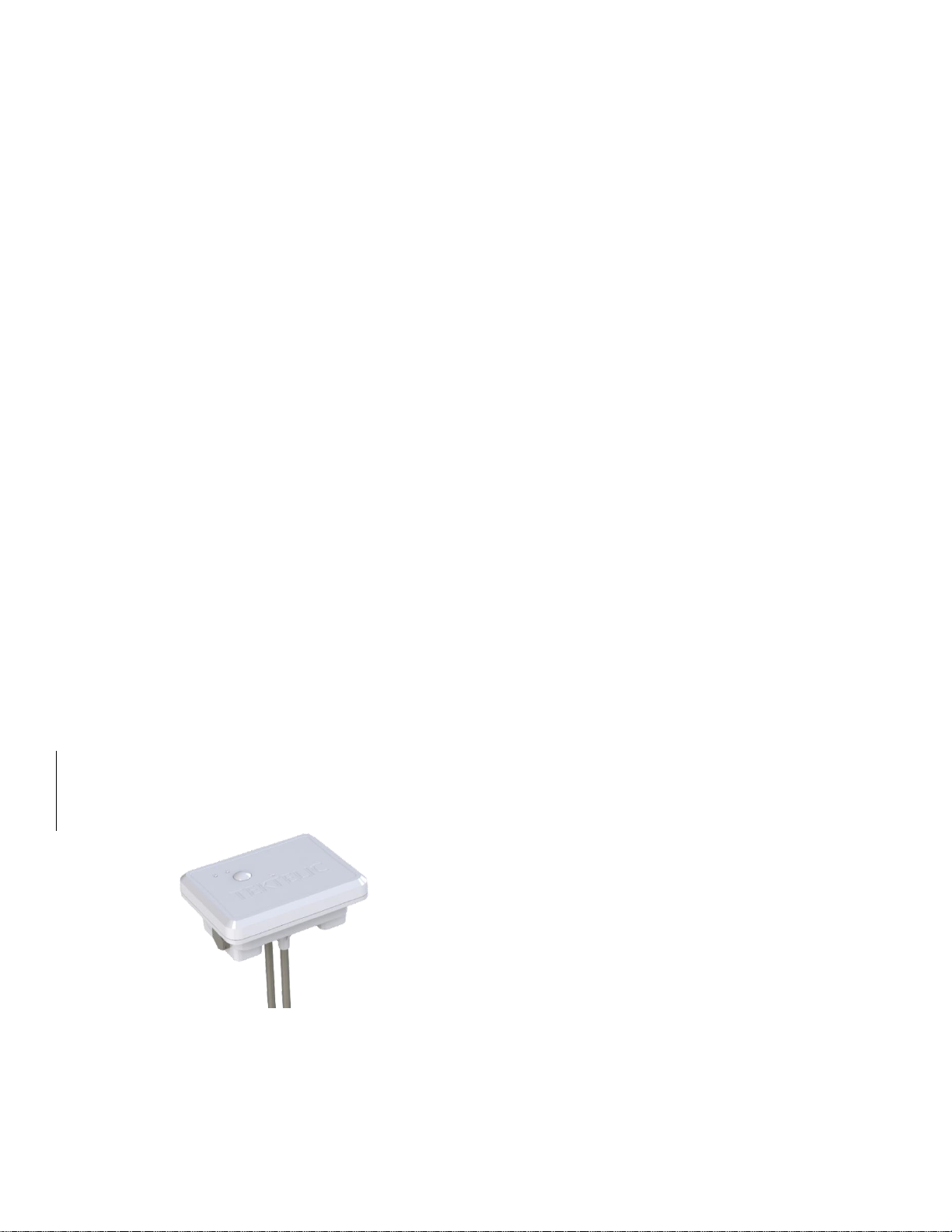
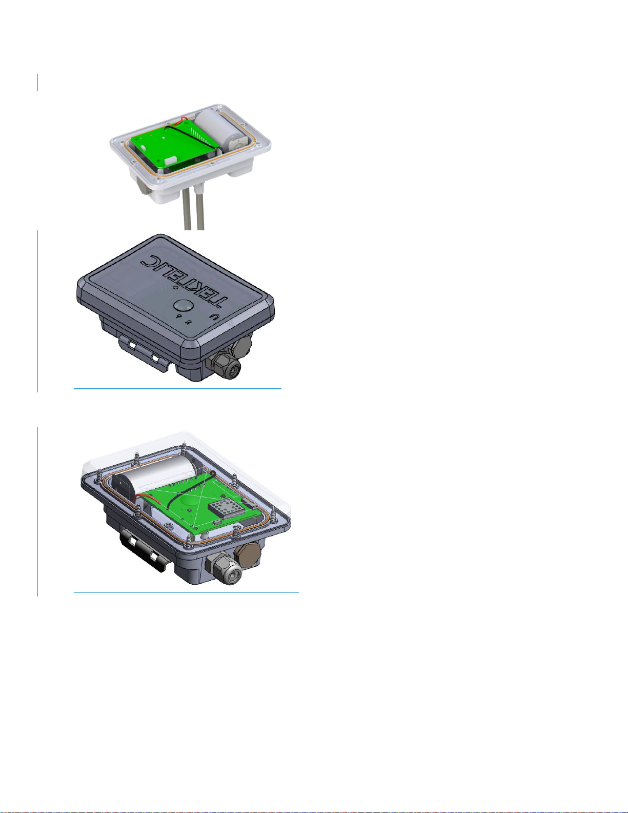
Figure 1 illustrates the Agriculture Sensor Soil Surface Mount Model in the enclosure.
a) Exterior view
b) Inside view
Figure 1 Agriculture Sensor Soil Surface Mount Model
LoRa Agriculture Sensor User Guide T0005978_UG Version # 1.9
TEKTELIC Communications Inc. Confidential Page 8 of 22
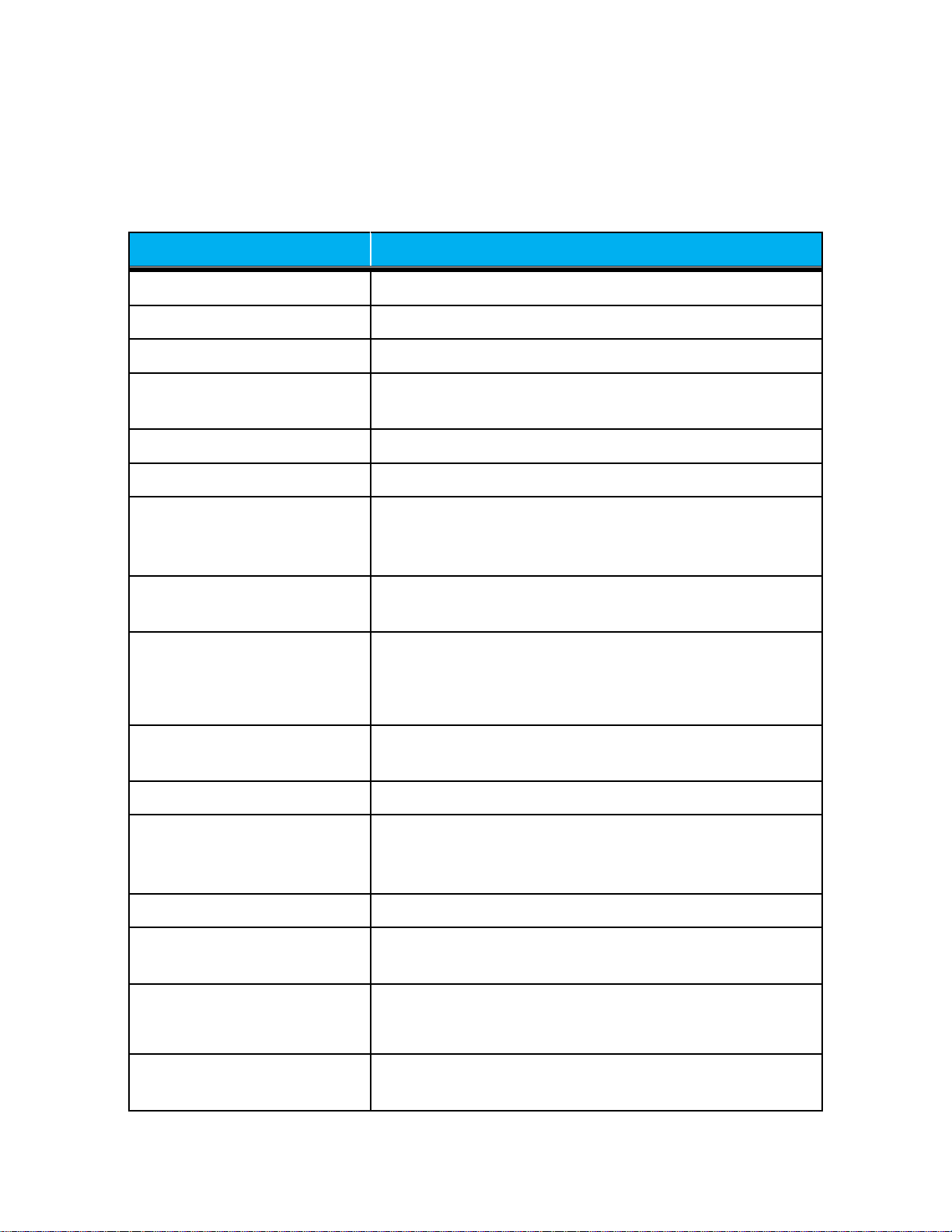
Figure 2 illustrates the Agriculture Sensor Elevated Mount Model in the Enclosure.
a) Exterior view
b) Inside view
Figure 2 Agriculture Sensor Elevated Mount Model

LoRa Agriculture Sensor User Guide T0005978_UG Version # 1.9
TEKTELIC Communications Inc. Confidential Page 9 of 22
1.2 Physical Interfaces
Figure 3 below illustrates the customer accessible interfaces for the Agricultural Sensor. All
models share the same layout.
Legend:
1A = Input 2+ (RES) 1B = Input 1+ (RES)
2A = Input 2- 2B = Input 1-
3A = Input 3 (Thermistor 1)*3B = Moisture 1 (Watermark 1)*
4A = Input 3 (Thermistor 1)*4B = Moisture 1 (Watermark 1)*
5A = Input 4 (Thermistor 2)*5B = Moisture 2 (Watermark 2)*
6A = Input 4 (Thermistor 2)*6B = Moisture 2 (Watermark 2)*
7A = GND (RES) 7B = Power (RES)
RES = Reserved pins for Soil Surface Mount Module Only
*NOTE there is no polarity on either the Thermistors or Watermarks that are shipped in the kit
with the Elevated Pole Module. The wires can be installed into the terminal block pins either
way.
Figure 3 Agriculture Sensor Connector Block
LoRa Agriculture Sensor User Guide T0005978_UG Version # 1.9
TEKTELIC Communications Inc. Confidential Page 10 of 22
1.3 Specifications
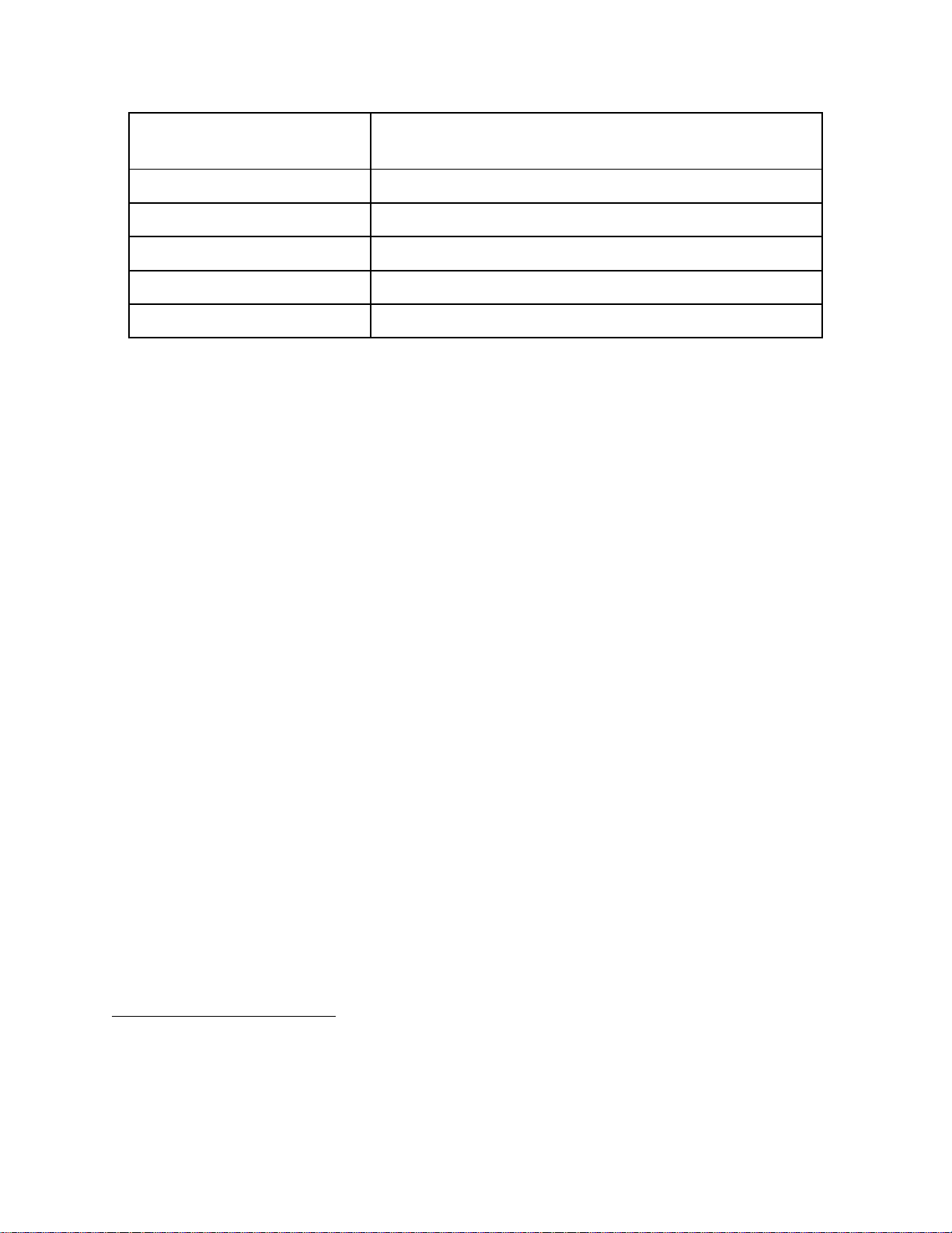
The Agriculture Sensor specifications are listed in Table 2.
Table 2: Agriculture Sensor Specifications
Attribute
Specification
Use Environment
Outdoor
Environmental Rating
IP67
Operating Temperature
-40°C‒85°C
Storage Temperature for
Optimal Battery Life
-40°C‒75°C
Operating Relative Humidity
0%‒100%, condensing
Storage Relative Humidity
0%‒100%, condensing
Size
Soil Surface Mount Sensor: 120 mm x 90 mm x 58 mm
(H=161mm with probes)
Elevated Mount Sensor: 120 mm x 90 mm x 47 mm
Weight
Soil Surface Mount Sensor: 224g
Elevated Mount Sensor: 220g (233g with mounting plate)
Power Source
Battery powered: 1x C-cell Lithium Thionyl Chloride (LTC)
3.6V
NOTE: If replacing the battery, please ensure it is
inserted with the correct polarity.
Network
technology/Frequency band
LoRaWAN in multiple variants (see Table 1):
US 902-928 MHz, EU 863-870 MHz
Air Interface
LoRa
Battery Lifetime
At least 10 years with a baseline use case: transmission
at maximum power every 15 minutes at room
temperature
Maximum Tx Power
22 dBm
LED
Green: Joining the network activity
Red: LoRa TX or RX activity
Sensing Functions
MCU temperature, ambient temperature, ambient
humidity, ambient light, accelerometer, battery level,
water tension, soil moisture, soil temperature
MCU Temperature
Measurement Accuracy
< ±5°C between -40°C and 85°C
LoRa Agriculture Sensor User Guide T0005978_UG Version # 1.9
TEKTELIC Communications Inc. Confidential Page 11 of 22
Ambient Temperature
Measurement Accuracy
±0.2°C and ±2% RH within temperature measurement
range of -40°C to 125°C*
Ambient Light Range
0.01 to 65,535 lux
Soil Moisture, Input 11
1.33 –1.37MHz
Soil Temperature, Input 22
0.5 –1.5V
Input 3 & 43
0.3 –2.5V
Watermark (Input 5 & 6)4
80 –8000 Hz
*From the manufacturer datasheet.
1
Applicable to Soil Surface Mount only
2
Applicable to Soil Surface Mount only
3
Applicable to Elevated Pole only
4
Applicable to Elevated Pole only

LoRa Agriculture Sensor User Guide T0005978_UG Version # 1.9
TEKTELIC Communications Inc. Confidential Page 12 of 22
2Installation
2.1 Included Product and Installation Material
The following items are shipped with each sensor:
LoRa IoT Agriculture Sensor with battery installed.
A magnet to wake up the sensor from DEEP SLEEP.
2.2 Safety Precautions
The following safety precautions should be observed:
The Agriculture Sensor is not a toy, KEEP AWAY FROM CHILDREN.
Use only the specified Lithium Thionyl Chloride (LTC) cells.
Do not exceed the maximum specified terminal voltages.
All installation practices must be in accordance with the local and national electrical
codes.
Sensor inputs do not provide electrical isolation between each other.
2.3 Unpacking and Inspection
The following should be considered during the unpacking of a new Agriculture Sensor:
Inspect the shipping carton and report any significant damage to TEKTELIC.
Unpacking should be conducted in a clean and dry location.
Do not discard the shipping box or inserts as they will be required if a unit is returned
for repair or re-configuration.
2.4 Equipment Required for Installation
The following tools are required to install the Agriculture Sensor:
Torx T10 screwdriver (8 x enclosure screws)
Slotted screwdriver (internal terminal block connections)
Wire Stripper
Wire Cutter
LoRa Agriculture Sensor User Guide T0005978_UG Version # 1.9
TEKTELIC Communications Inc. Confidential Page 13 of 22
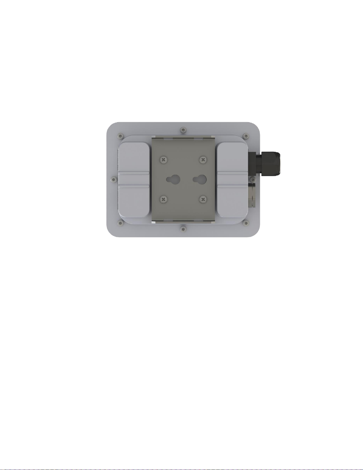
2.5 Elevated Mount Sensor Mounting
On the Elevated Mount model of the Agriculture Sensor, there is a mounting bracket on the
bottom of the unit. See Figure 4. These mounting holes can be used to screw the enclosure to a
solid surface. The recommended mounting screw size is M3 or #6. Mounting screws are not
provided with the sensor.
Figure 4 Mounting Holes
The mounting surface must be capable of holding > 2 kg [4.5 lbs]. Clearance must be provided
for the modules cable gland and input cable.
2.6 Cable Installation
The Elevated Mount Sensor enclosure is provided with a waterproof cable gland through which all
connections must be routed. The supplied cable gland size is PG-7. This gland supports cables with a
jacket outside diameter of 3.0 mm to 4.3 mm (0.118" to 0.169").
The I/O terminal blocks accept 30-16 AWG wire. Select a cable that meets the application
requirements and local and national electrical codes.
Figure 3 shows the terminal block wiring connections. To install the cable, first make the
appropriate connections between the input cable and the terminal block. Next dress the
internal wires so that the cable gland seals against the outer cable jacket. Finally, tighten the
cable gland.

LoRa Agriculture Sensor User Guide T0005978_UG Version # 1.9
TEKTELIC Communications Inc. Confidential Page 14 of 22
See Figure 3 on Page 9 for input connections. Signal connections should be connected to the
positive terminal (labeled ‘+’). Similarly, the return path should be connected to the negative
terminal (labeled ‘-’) of the matching I/O channel.
NOTE: Elevated Mount Sensor I/O are referenced to the sensor ground and are not isolated.

LoRa Agriculture Sensor User Guide T0005978_UG Version # 1.9
TEKTELIC Communications Inc. Confidential Page 15 of 22
3Power Up, Commissioning and Monitoring
3.1 Reed Switch Awakening Procedure
Note: Early versions of the Agriculture Sensor were shipped with tape over the positive terminal of
the battery, so if the wakeup pattern described below doesn’t work, the battery should be checked
and tape removed if necessary.
The Agriculture Sensor is equipped with a magnetic reed switch. The reed switch can be
operated by the provided magnet, and is used for the following purposes:
1) MCU reset upon observing a specified magnetic pattern:
This is mainly used to wake up the module from DEEP SLEEP and having it try to join the
network. When the module comes out of the factory, it is in the DEEP SLEEP mode,
5
and
can be activated using the specified magnetic pattern. Also, the same magnetic pattern
can just be used to reset the Agriculture Sensor during normal operation, getting it to
try to rejoin the network.
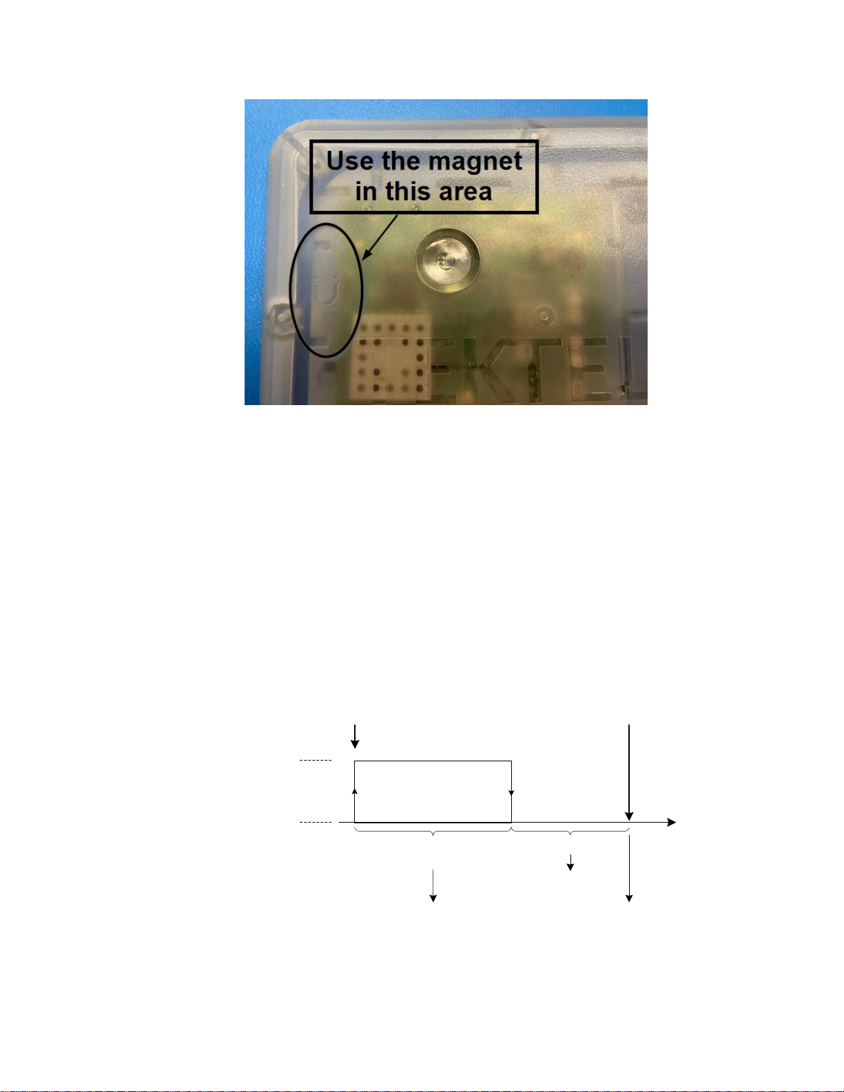
The magnetic pattern in this application is hard coded (not user configurable) as
illustrated in Figure 5. A magnet presence is achieved by attaching the magnet to the
enclosure at the magnet sign. A magnet absence is achieved by taking the magnet away
from the enclosure. The magnet sign is illustrated in Figure 5 below:
5
The Agriculture Sensor will go to DEEP SLEEP whenever the internal sleep button on the PCBA (labeled SW1) is
pressed. This is performed as the last step in the factory before closing the enclosure. The only ways to activate the
module out of DEEP SLEEP is to apply the specified magnetic pattern or to open the enclosure and remove and
reinsert the battery.
LoRa Agriculture Sensor User Guide T0005978_UG Version # 1.9
TEKTELIC Communications Inc. Confidential Page 16 of 22
Figure 5 Reed switch location
Here are the steps as illustrated in Figure 6:
1. Attach the magnet to the enclosure at the magnet sign, and hold it for at least 3
sec but less than 10 sec.
2. Keep the magnet away for at least 3 sec.
As soon as the specified magnetic pattern is applied to the Agriculture Sensor, the
Agriculture Sensor is reset and tries to join the network. It may take about 10 sec from
the Agriculture Sensor reset to seeing the LED activity showing join attempts. Therefore,
as step 1 in the above is completed, it takes about 13 seconds before observing the LED
activity (if step 2 is respected).
Figure 6 Agriculture Sensor magnetic reset/wake-up pattern
3 sec
> 3 sec
< 10 sec
t
Pattern starts Pattern ends
Magnet Present
Magnet Absent
Keep magnet attached
for at least 3 sec but
no longer than 10 sec
Magnet removed
Module reset
(and activated if
in DEEP SLEEP)
LoRa Agriculture Sensor User Guide T0005978_UG Version # 1.9
TEKTELIC Communications Inc. Confidential Page 17 of 22
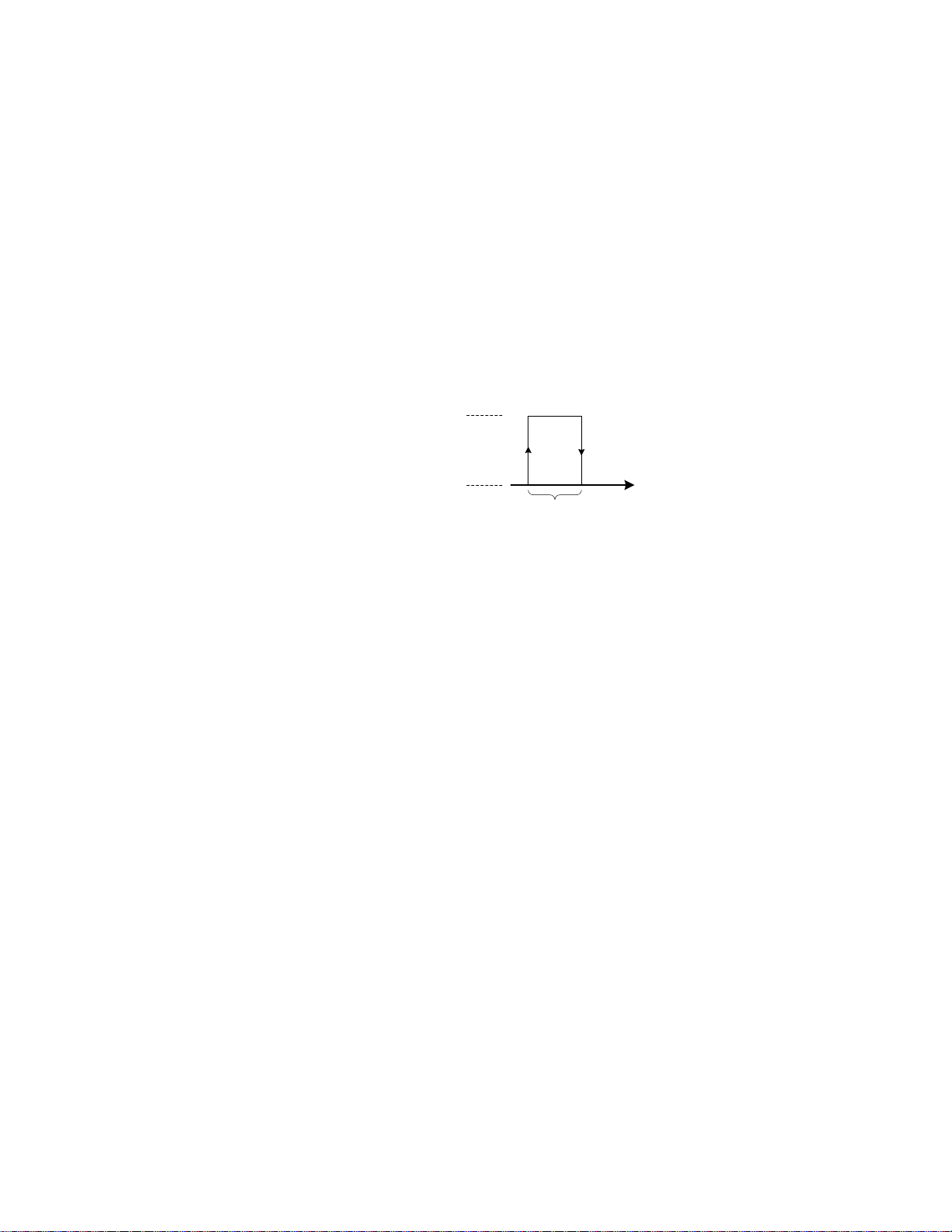
2) Triggering the Agriculture Sensor to uplink something upon observing a magnetic
pattern:
This is used to get the LoRaWAN Class-A Agriculture Sensor to open a receive window so
it can receive DL commands from the NS, or simply to trigger the Agriculture Sensor to
uplink some desired transducer data.
The magnetic pattern in this case is not user configurable, and involves attaching and
taking away the magnet to and from the magnet sign at the top of the enclosure once,
all in less than 2 sec, as shown in Figure 6. It is important to note here that mistakenly
holding the magnet attached to the module for more than 3 sec may trigger a module
reset, as explained in item 1.
Figure 7 Agriculture Sensor magnetic UL-triggering pattern
Note: Replacing the batteries of the Agriculture Sensor does not cause the Agriculture Sensor
to go to DEEP SLEEP. As soon as a new battery is inserted, the Agriculture Sensor boots up and
tries to join a LoRaWAN network.
3.2 Commissioning
To add your sensor to the Network Server, you will need to enter the DevEUI, AppEUI and
AppKey that were provided for your device from Tektelic.
< 2 sec
t
Magnet Present
Magnet Absent

LoRa Agriculture Sensor User Guide T0005978_UG Version # 1.9
TEKTELIC Communications Inc. Confidential Page 18 of 22
4Battery Replacement
Open up the Agriculture Sensor using a #10 Torx screwdriver. The Agriculture Sensor has 8x
enclosure Torx screws at the bottom. Be careful not to misplace the silicone cover gasket from
the top lid.
Replace the battery. The Agriculture Sensor accepts C-size, 3.6 V, LTC batteries. The allowed
replacement batteries are as follows:
oXeno Energy, part number: XL-145F
oTadiran Battery, part number TL-4920/S
oTadiran Battery, part number TL-5920/S
Once the Agriculture Sensor is powered and tries to join (see Section 5.3 for LED behavior),
replace the cover and gasket. Make sure that the gasket is properly seated in the cover before
placing on the Agriculture Sensor housing. Tighten the 8 cover screws to 2.5 lbf-in (30 N-cm).

LoRa Agriculture Sensor User Guide T0005978_UG Version # 1.9
TEKTELIC Communications Inc. Confidential Page 19 of 22
5Operation, Alarms, and Management
5.1 Configuration
The Agriculture Sensor supports a full range of Over-the-Air (OTA) configuration options.
Specific technical details are available in the Agriculture Sensor Technical Reference Manual.
All configuration commands need to be sent OTA during a sensor’s downlink windows.
5.2 Default Configuration
The default configuration of the Soil Surface Mount Sensor for reporting transducer readings
includes the following:
Table 3: Default Configuration - Soil Surface Mount
Seconds per Core Tick
900 (15 min)
Ticks per battery voltage measurement
96 (24-hours)
Ticks per Ambient Temperature
1 (15 min)
Ticks per Ambient Relative Humidity
1 (15 min)
Ticks per Soil Moisture
1 (15 min)
Ticks per Soil Temperature
1 (15 min)
Ticks per Ambient Light
1 (15 min)
The default configuration of the Elevated Mount Sensor for reporting transducer readings
includes the following:
Table 4: Default Configuration - Elevated Mount
Seconds per Core Tick
900 (15 min)
Ticks per battery voltage measurement
96 (24-hours)
Ticks per Watermark 1
1 (15 min)
Ticks per Watermark 2
1 (15 min)
Ticks per Ambient Light
1 (15 min)
5.3 LED Behaviour
The LED’s are located on the top of the Agricultural Sensor. See Figure 8.

LoRa Agriculture Sensor User Guide T0005978_UG Version # 1.9
TEKTELIC Communications Inc. Confidential Page 20 of 22
Figure 8 LED Location
During the boot and join procedure:
Both LEDs will come on briefly when power is first applied.
After a small delay (< 1 second) the LEDs will turn off and one of them will blink briefly.
oIf the System (green) LED blinks, then all health checks on the board have
passed.
oIf the LoRa LED (red) blinks, then one of the health checks has failed. Consider
replacing the battery, or moving the sensor to an environment within the
temperature range.
Immediately after the delay, the join procedure will begin. During the time the System
LED will blink continuously until the sensor joins a network.
The LoRa LED will now blink whenever LoRa activity occurs on the sensor (transmitting
or receiving packets).
During normal operation:
The LoRa LED will blink whenever LoRa activity occurs on the sensor (transmitting or
receiving packets)
The System LED can be controlled via the downlink command interface.
This manual suits for next models
3
Table of contents
Other TEKTELIC Communications Accessories manuals

TEKTELIC Communications
TEKTELIC Communications TUNDRA User manual

TEKTELIC Communications
TEKTELIC Communications Kona All-in-One Home Sensor Series User manual

TEKTELIC Communications
TEKTELIC Communications Kiwi User manual

TEKTELIC Communications
TEKTELIC Communications TUNDRA User manual

TEKTELIC Communications
TEKTELIC Communications T0006623 User manual

TEKTELIC Communications
TEKTELIC Communications Kona All-in-One Home Sensor User manual

TEKTELIC Communications
TEKTELIC Communications Kona Product manual

TEKTELIC Communications
TEKTELIC Communications T0004893 Product manual

TEKTELIC Communications
TEKTELIC Communications T0004437 User manual


