The CliniMix®CMV2 Wall Mounted Hands Free Point Use mixing valves must be installed using the
appropriate Standard, Code of Practice and legislation applicable to point of install.
The CliniMix®CMV2 Wall Mounted Hands Free Point Use mixing valves must be installed by a licensed
plumber.
If the valve is not installed correctly then it will not function correctly and may put the user in danger. It may
also void the warranty of the valve.
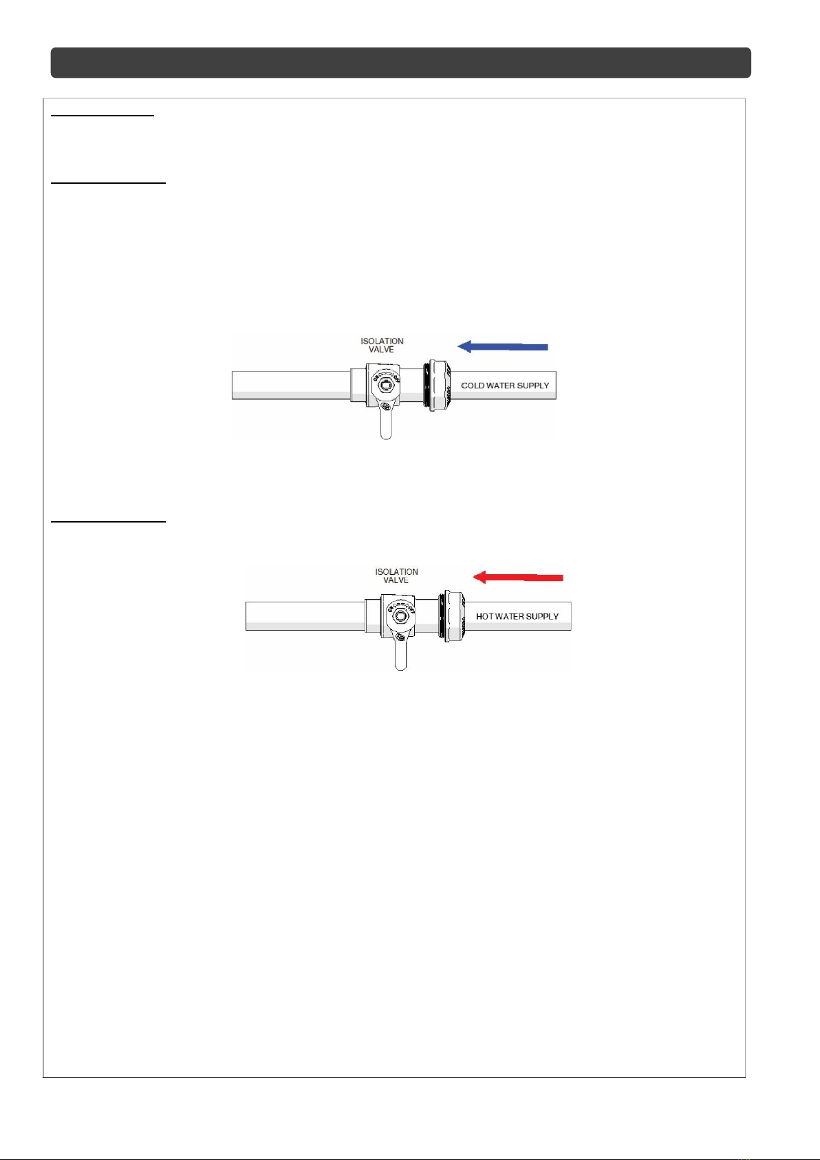
Prior to the installation of the valve, the system must be checked to ensure that the system operating
conditions fall within the recommended operating range of the CliniMix®CMV2 Wall Mounted Hands Free
Point Of Use mixing valve. If the hot water supply temperature is greater than 80° Celsius, the valve may be
damaged. If the temperature of the hot water will rise above 80° Celsius a suitable temperature limiting valve
must be fitted to the hot water supply, prior to the inlet fittings. This temperature limiting valve must be
installes dynamic supply pressures are
500kPa or less. If either supply pressure exceeds 500kPa then a suitable pressure reducing valve must be
fitted prior to the inlet control valve to reduce the pressure to an acceptable limit.
performance from the valve it is recommended that the inlet pressures are balanced to within 10% of each
other.
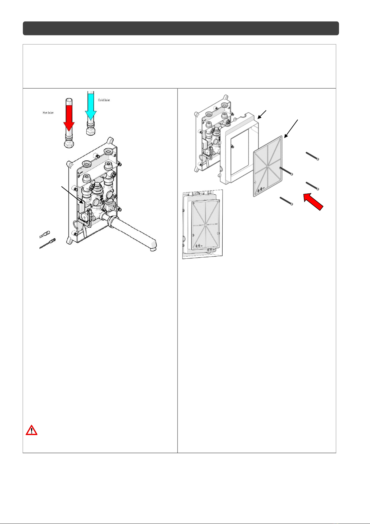
To ensure that the mixing valve operates correctly, it is necessary that the pipe-work is thoroughly flushed
with clean water before the valve is installed. This will remove any physical contaminants from the pipe-work,
ensuring trouble-free operation. During the flushing procedure, care should be taken to prevent water
damage occurring to the surrounding area.
The valve should be installed so it can be easily accessed for maintenance or servicing.
During installation or servicing, heat must not be applied near the mixing valve or inlet fittings, as this will
damage the valve and inlet fittings internals. Failure to comply with this requirement will damage the valve
and fittings. It will put the user at risk, and it will void the warranty of the valve.
Note: To effectively control microbial hazards during system design, installation, commissioning and maintenance, the
requirements of local legislation shall be adhered to.
Note: In some installations, certain types of tapware devices such as flick mixers and solenoid valves are used. The water
pressure may be seen to spike outside that recommended for the valve, during rapid shut off conditions with these types of
devices. Even if the spike only lasts a split second it is still considered to be outside the operating conditions and may cause
the valve to operate incorrectly. In the event that this does occur, measures must be taken to control the spike, such as the
installation of an inline pressure reducing valve directly before the valve inlets.