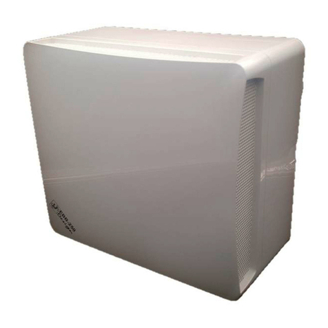
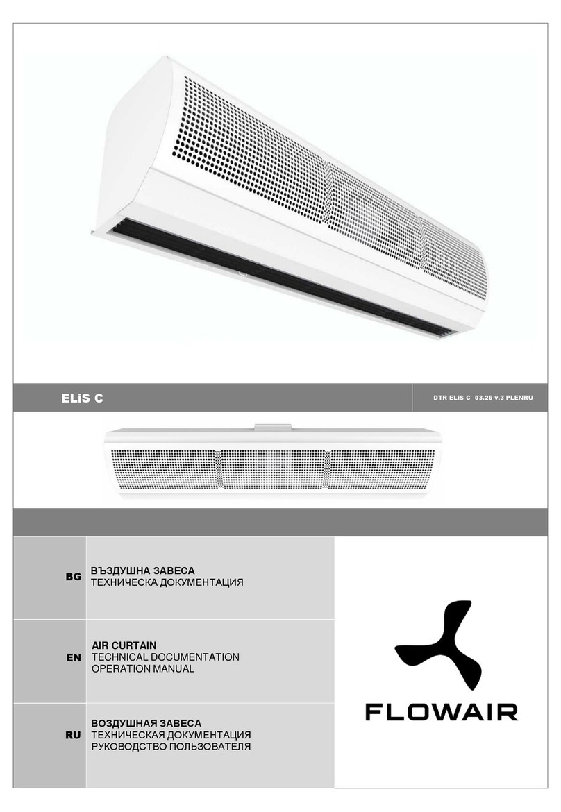
Ferono FK90E3 User manual

USER MANUAL
Air curtain with an electric heater
Models:
FK90E3
FK120E3
FK150E3
FK200E3
FK90E
FK120E
FK150E
FK200E
www.ferono.com [email protected]

Thanks for purchasing this Air Curtain,
Please read these instructions carefull before use.
1、PRODUCT INTRODUCTION
As one of the new top-class products for modern decoration, air curtain is also matched with the
air conditioner. And it is installed at the entrances of supermarket, theater, meeting room, hotel, office
room, working shop and storeroom to prevent the dust, mosquito and nocuous air, and so on.
2、MODEL INTRODUCTION
KxxxEx
Suppl t pe: E: 1 phase, E3: 3 phase
T pe of curtains: With electric heater
Diameter of the wind wheel 90: 90 cm, 120: 120 cm, 150: 150 cm,
Code of air curtain
Note: code of improved design of:
Y: t pe of wireless remote control D: t pe of AC electrical heating
D: single phase 3D: three phases
3、IDENTIFICATION & INSTALLATION DIMENSIONS
4、INSTALLATION CAUTION
Must follow the following requests when installing air curtain:
4.1 Please install the unit in a sturd place to avoid
the shaking and ensure its securit (because it
ma be causes the wall becoming flexible or
shaking and noise.
4.2 Please install the unit inside the room.
D
E
F
BACK
Supply type: E: 1 phase, E3: 3 phase
Type of curtains: With electric heater
Diameter of the wind wheel 90: 90cm, 120: 120cm, 150: 150cm, 200: 200cm
Code of air curtain
FK90E
FK90E3
FK120E
FK120E3
FK150E
FK150E3
FK200E
FK200E3
Model
A B C D E F
900
1200
1500
2000
440
840
90 105 195 265

4.3 Don’t install the unit too low, no less than 2.3
meters from the ground.
4.4 When the entrance is wider than the unit,
it is recommended to install two or more
units in parallel. In this case, provide 20-
40mm gaps between the units.
4.5 Don’t allow gaps between the unit and the
wall. When hanging it from the ceiling, using
the enclosed ceiling brackets.
4.6 Don’t install the unit in a place where it is
splashed b water, exposed to excessive
steam, explosive gas or corrosive gas.
5、INSTALLATION
A、Installing on the concrete wall:
5.1.1 Removed the mounting plate
Unclamping the fixed screws on the back of
main bod to removed the mounting plate.
M O U N T I N G PIATE
FIXI N G S C R E W
5.1.2 Fix the bolts in the proper position (Fix
the position with the mounting plate and
pour cement into the bolt holes.)
CONCR E T E
13 -15m m 7 0 m m
φ40- 50mm
5.1.3 When the cement has freeze, fit the mounting
plate (use the washer and nut according to the
following)
5.1.4 Install the main bod
Set the main bod onto the upper end of the
mounting plate and clamp it as shown.

B、Installing on the wooden wall:
5.3.1 Remove the mounting plate from main bod
(Same as step 5.1.1)
M O U N T I N G PIATE
FIXI NG SC R E W
5.3.2 Fixing ceiling brackets as Fig.
CDC
NUT
S PR IN G WA S HE R
WAS H E R
5.3.3 Set the mounting plate on the ceiling
brackets and ensure safe & fixing (use the bolts
attached to the ceiling brackets as Fig. Using
the ceiling brackets to hang from the ceiling,
the position of mounting plate can be adjusted
in the limit of 100mm.
5.3.4 Do the same as step A to install the
main bod .
5.2.1 Fix the mounting plate in the proper
positions with tapping screw.
MOODEN SC REW
MOUN TI N G PI A T E
5.2.2 Same as the step 5 of A
C、Hanging from the ceiling

6、HEATING MODEL TECHNICAL PARAMETER
POWER
ITEM
SINGLE PHASE
( 230V~,MAIN LINE:L、N)
THREE PHASES
( 400V~ MAIN LINE:A、B、C、N)
HEATER
POWER(kW )3 4 5 6 8 10 14 3 4 5 6 8 10 14
MAIN
LINE(mm2)1. 5 2.5 2.5 4 .0 6.0 10 10 1.0 1.0 1.0 1.5 2.5 2 .5 4.0
EARTH LINE
(mm2)0.75 1. 0 1.0 1.5 2.5 2.5 4. 0 0. 75 0. 75 0.75 0. 75 1. 0 1. 0 2.5
WHITE
BLUE(BROWN/RED
YELLOW
c
MOTOR
ORANGE
(YELLOW
BLACK
YELLOW-GREEN
RECEIVER
IC
HEATER
HEATER
B CN A PN
THERMAL CUT-OUT
THERMAL CUT-OUT
THERMAL CUT-OUT
on
com 1
2
com on
on
com 3
I/O
RECEIVER
BROWN
BLUE WHITE
GREY
YELLOW-GREEN
WHITE
BLUE(BROWN/RED
YELLOW
c
MOTOR
ORANGE
(YELLOW
BLACK
YELLOW-GREEN
RECEIVER
IC
HEATER
HEATER
LN PN
THERMAL CUT-OUT
THERMAL CUT-OUT
THERMAL CUT-OUT
on
com 1
2
com on
on
com 3
I/O
RECEIVER
BROWN
BLUE WHITE
GREY
YELLOW-GREEN
7、OPERATION
7.1. Controlled b remote controller
a. Press “ON/OFF” button to turn ON the unit. Main receiver receives the signal with the sound of “beep” to start
working with the green light in cool mode at high speed “H”. Press “ON/OFF” button again to turn OFF.
b. When the unit is working at the above a. situation, press “COOL” button in the Remote controller, receiver receives
the signal with the sound of “beep” and switch high speed to low speed “L”. Meanwhile there is a green light
displa in the receiver. Press “COOL” button again, the unit will switch low speed to high speed. So when the unit
is working at cool mode, press “COOL” button can switch air curtain working under the c cle of Low or High
speed.
c. FOR SINGLE PHASE UNIT: When the unit is working at the above b. situation, press “HEAT” in the remote
controller, receiver receives the signal with the sound of “beep” and switch cool mode to heating mode at low
power. Meanwhile there is a Red light displa in the receiver. Press “HEAT” button again, the unit will switch low
power to high power. Meanwhile there is TWO Red lights displa in the receiver. Press “HEAT” button again, the
unit will switch heating mode to cool mode and the red lights displa change to green light in the receiver. So when
the unit is working at cool mode, press “HEAT” button can switch air curtain working under the c cle of heating
low power, heating high power or cool mode.
LINE SIZE
FK90E3
FK120E3
FK150E3
FK200E3
FK90E
FK120E
FK150E
FK200E
160
200
230
350
160
200
230
350
2
2.7
3.3
4.6
3
4
5
7
4
5.3
6.7
9.4
6
8
10
14
6
8
10
14
-
-
-
-
115
115
400/50
230/50
35-45 8.5
35-45 8.5
1000
1500
1900
2800
1000
1500
1900
2800
55-57
56-58
57-59
59-61
55-57
56-58
57-59
59-61
14.5
17
22
26
14.5
17
22
26
MODEL
Diam.
Of
Wheel
(mm)
Voltage
/Freq.
(V〜/Hz)
Motor
Power
(W)
Heater power
(KW)
I
II
III
Temp.
(K)
Max.air
speed
(m/s)
Air
volume
(m3/h)
Noise
(dB)
Net
weight
(Kg)

FOR THREE PHASES UNIT: When the unit is working at the above b. situation, press “HEAT” in the remote
controller, receiver receives the signal with the sound of “beep” and switch cool mode to heating mode at low
power. Meanwhile there is a Red light displa in the receiver. Press “HEAT” button again, the unit will switch low
power to middle power. Meanwhile there is TWO Red lights displa in the receiver. Press “HEAT” button again,
the unit will switch middle power to high power. Meanwhile there is THREE Red lights displa in the receiver.
Press “HEAT” button again, the unit will switch heating mode to cool mode and the red lights displa change to
green light in the receiver. So FOR THREE PHASES MODEL when the unit is working at cool mode, press
“HEAT” button can switch air curtain working under the c cle of heating low power, heating middle power,
heating high power or cool mode.
d. When the unit works at cool mode, press “ON/OFF” button to turn OFF the unit.
e. When the unit works at heating mode, press “ON/OFF” button, receiver receives the signal with the sound of “beep”
and switch to cool mode at high speed, the indication light turns to green flicker light. The unit will continue to work
in cool mode for 3 minutes and then stop. (This is to ensure the heater is been cooled down and has 3 minutes dela
stop).
7.2. Controlled b the control panel in the unit is the same function as 7.1.
7.3. Overheat protection:
When the air curtain works at heating mode, there is overheat protection. When the heater temperature is
overheating, heating mode will stop and switch to cool mode automatic, at the same time the indication light
change to green light. When the temperature drop down to a certain temperature, if want the unit to work at heating
mode, press “HEAT” button to continue to work heating mode.
8、CAUTIONS
1)、Turn off the interrupter or disconnect the plug for an maintenance service.
2)、Turn off the interrupter or disconnect the plug in case of a non product use.
3)、Make sure that the product provides a ground wire.
4)、The pictures shown on this manual are illustrative onl .
5) 、
This appliance is not intended for use b persons (including children) with reduced ph sical, sensor or mental
capabilities, or lack of experience and knowledge, unless the have been given supervision or instruction
concerning use of the appliance b a person responsible for their safet .
6)、Children should be supervised to ensure that the do not pla with the appliance.
7) 、
If the suppl cord is damaged, it must be replaced b the manufacturer, its service agent or similarl qualified
persons in order to avoid a hazard.
9、ATTENTION
a)、Use the unit at the rated voltage and frequenc indicated on the nameplate.
b)、Do not wet the product electrical components.
c)、Never use petrol, benzene, thinners or an other such chemical to clean the unit.
d)、Routine maintenance must be done ever ear.

FERONO
www.ferono.com
WARRANTY CARD
The warranty is valid only with invoice
Air curtain model . . ...............................................
Serial number........................................................
Sale date ..............................................................
Invoice number . . .................................................
................ Service sign and stamp
Instalation date ....................................................
Instalation adress . . . . .........................................
Electrical permission number..............................
................ Service sign and stamp
CONFIRMATION OF INSTALLATION BY AUTHORIZED SERVICE

This manual suits for next models
7
Table of contents
Popular Heater manuals by other brands

LuxenHome
LuxenHome WHIF993 instruction manual

MrHeater
MrHeater MH35LPTS Operating instructions and owner's manual

BLACK DECKER
BLACK DECKER BHDT118 instruction manual

Combustion Research
Combustion Research reflect-o-ray eds 3.5 Installation operation & maintenance

Kingsman Fireplaces
Kingsman Fireplaces IDV24 installation instructions

Zodiac
Zodiac JXi 200 Installation and operation manual

Rointe
Rointe Lyon electric pro instruction & installation guide

Dimplex
Dimplex XLS6N Installation and operating instructions

UNMAK
UNMAK 10 P 300 Installation and user manual

Kooper
Kooper 5913643 User instructions

Toyotomi
Toyotomi DC-100C Operation and maintenance instructions

Gree
Gree FP ZD-K(E) Series user manual