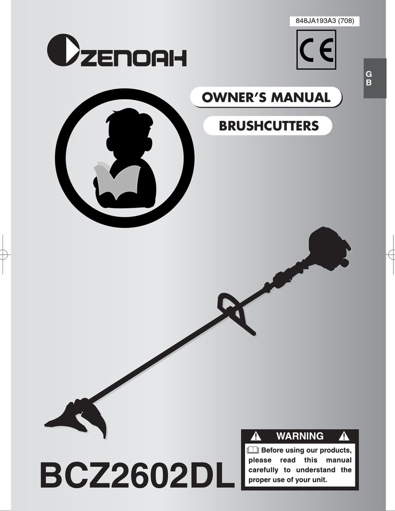
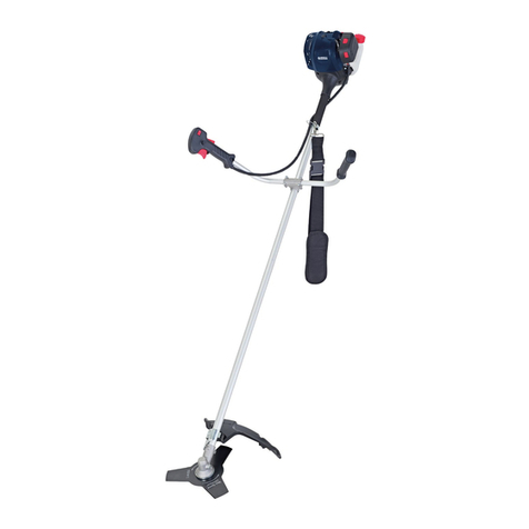
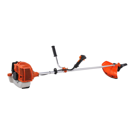
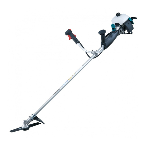
FERREX 700710 User manual

700710
52CC 2 STROKE
BRUSHCUTTER,
LINE TRIMMER
User Manual
Product
Info
https://help.tools/
Read all safety warnings and all instructions
thoroughly before operating this product.
Ensure you keep your manual in a
safe place for future reference.
IM ed 4; 02/2020

QR codes take you where you want to go
quicky and easily
Whether you require product information, spare parts or accessories,
details on warranties or aftersales service, or if you want to watch
a product demonstration video, our QR codes will take you there in
no time at all.
What is a QR code?
A QR-code (QR=Quick Response) is a type of matrix that can be read
with a smartphone camera and that contains a link to a website or
contact details, for example.
Advantage: You are not required to manually enter a website address
or contact details.
How it works
To scan the QR code, all you need is a smartphone with QR codes reader
software and an Internet connection*. This type of software can be
downloaded for free from your smartphone’s app store.
Try it out now
Just scan the QR code with your smartphone and
nd out more about the Aldi product you have
purchased*.
* Depending on your tarif you may be charged for the connection.
Product
Info

Contents
Pack contents /parts 2
Description of symbols 3
General safety warnings 4
Additional Safety Rules for Petrol Products 7
Additional Safety Rules for Petrol Brushcutters 8
Parts List 10
User Instructions 12
Preparation 28
Operation of the Brushcutter / Line Trimmer 30
Maintenance 33
Warranty 36
Enyironmental protection 37
What your 5 year warranty means 37
Accessories and After Sales Parts 38
Troubleshooting 39
Specications 40

52cc 2 Stroke Brushcutter / Line Trimmer
AFTER SALES SUPPORT
MODEL: №. SBC52 • 02/2020 • 700710 (toll free)
4
Pack contents / parts
Congratulations on the purchase of your FERREX® 52cc 2 Stroke
Brushcutter / Line Trimmer. When you open your packaging, rst remove
all items and check there are no parts damaged or missing. If you nd
anything wrong, do not operate the product until the parts have been
replaced or the fault has been rectied. Failure to do so could result in
serious personal injury.
IMPORTANT INFORMATION.
NOTE: This is a 2 stroke Line Trimmer and requires pre-mixing fuel with
2-stroke oil BEFORE starting. Fresh unleaded fuel must be used in this
unit. Do NOT use Ethanol based fuels.
Intended use of the 52cc 2 Stroke Brushcutter / Line Trimmer
NOTE: This product is for private domestic DIY use only.
It is not suitable for commercial or trade use.
This Line Trimmer has been designed for trimming lawn edges and
grass around shrubs and trees.
The Brushcutter has been designed for cutting and clearing grass,
thick weeds, vegetation and shrubs.
Contents of carton
1 x Brushcutter / Line Trimmer
1 x
Brushcutter / Line trimmer Guard (+ 4 x bolts + 4 x nuts + 8 x washers) (not tted)
1 x 3T Brushcutter Blade (not tted)
1 x Spool & Line Assembly (not tted)
1 x P handle (+ 4 x hex bolts + 4 x nuts + 8 x washers) (not tted)
1 x Double Shoulder Strap Harness
1 x Spark Plug Spanner / Blade Nut Wrench / Screwdriver Combination
2 x Allen Key (4mm & 5mm) 1 x 8mm/10mm Spanner
1 x Flathead Screwdriver 1 x Fuel / Oil Mix bottle
1 x Instruction Manual 1 x Quick Start Guide
1 x Warranty Card & details
2

AFTER SALES SUPPORT
(toll free)
MODEL: №. SBC52 • 02/2020 • 700710
52cc 2 Stroke Brushcutter / Line Trimmer
5
3
Description of symbols
The instruction manual or rating plate on your product may show symbols. These
represent important information about the product or instructions on its use.
Warning.
Conforms to relevant standards for electromagnetic compatibility.
Read these instructions for use carefully.
Wear eye protection. Wear hearing protection.
Wear headwear protection.
Wear safety gloves. Do not put in water.
Wear safety footwear. 60 Months Warranty
Risk of hand injuries.
Keep children and
bystanders away while
operating
Sharp blade; Risk of hand and feet injuries.
Thrown objects and rotating line can cause severe injury.
Do not operate the unit without the safety guard in place.
Keep away from rotating cutter.
Use at a distance of at least 15m from other people.
Choke control
Start position (choke closed).
Run position (choke open).
Noise label rating 110dBA (taken at 4 metres) you must wear ear
pro tection at all times.
60
Extremely hot surface. Do not touch
a hot muer, gear box or cylinder,
you may get burned. These parts get
extremely hot from operation and
remain hot for a short time after the
unit is turned o.

General safety warnings
WARNING! Read all safety warnings and all instructions.
Failure to follow the warnings and instructions may result
in electric shock, re and/or serious injury.
The word power tool used in the following warnings and
throughout this manual refers to BOTH electrical power tools
and ALSO petrol driven power tools.
This unit may not be used by people (including children) with reduced
physical, sensory or mental capacities, with a lack of experience and without
the appropriate knowledge, unless they are supervised by someone who is
responsible for their safety or have been instructed by such a person with
regard to how the unit is to be operated. Children should be supervised to
ensure that they do not play with the device.
Save all warnings and instructions for future reference
1. Work area safety
a. Keep work area clean and well lit. Cluttered or dark areas invite
accidents. Rags, cloths, cord, string and similar items should never be left
around the work area.
b. Do not operate power tools in explosive environments, such as in the
presence of ammable liquids, gases, or dust. Power tools
create sparks, which may ignite the dust or fumes.
c. Keep children and bystanders away while operating a power tool.
Distractions can cause the operator to lose control.
2. Electrical safety
a. Power tool plugs must match the outlet. Never modify the plug in
any way. Do not use any adapter plugs with grounded power tools.
Unmodied plugs and matching outlets will reduce risk of electric shock.
b. Avoid body contact with grounded surfaces such as pipes, radiators,
ranges and refrigerators. There is increased risk of electric shock if your
body is grounded.
c. Do not expose power tools to rain or wet conditions. Water entering
4

a power tool will increase the risk of electric shock.
d. Do not abuse the cord. Never use the cord for carrying, pulling or
unplugging the power tool. Keep cord away from heat, oil, sharp edges or
moving parts. Replace damaged cords immediately.
Damaged or entangled cords increase the risk of electric shock.
e. When operating a power tool outdoors, use an extension cord suit-
able for outdoor use. Use of a cord suitable for outdoor reduces the risk
of electric shock.
3. Personal safety
a. Stay alert, watch what you are doing and use common sense when
operating a power tool. Do not use a power tool while you are tired or
under the inuence of drugs, alcohol or medication. A moment of
inattention while operating power tools may result in serious
personal injury.
b. Use personal protective equipment. Always wear eye protection.
Protective equipment such as dust mask, non-skid safety shoes, hard hat,
or hearing protection will reduce personal injures.
c. Prevent unintentional starting. Ensure the switch is in the“o”
position before connecting to power source and/or battery pack,
picking up or carrying the tool. Carrying power tools with your nger on
the switch or energising power tools that have the switch on
invites accidents.
d. Remove any adjusting key or wrench before turning the power tool
on. A wrench or key left attached to a rotating part of the power tool may
result in personal injury.
e. Do not overreach. Keep proper footing and balance at all times.
This enables better control of the power tool in unexpected situations.
f. Dress properly. Do not wear loose clothing or jewellery. Keep your hair,
clothing and gloves away from moving parts. Loose clothes, jewellery or
long hair can be caught in moving parts.
g. If devices are provided for the connection of dust extraction and
collection facilities, ensure these are connected and properly used.
Use of dust collection can reduce dust-related hazards.
5

General safety warnings
4. Power tool use and care
a. Do not force the power tools. Use the correct power tool for your
application. The correct power tool will do the job better and safer at
the rate for which it was designed.
b. Do not use the power tool if the switch does not turn it“on” and
“o”. Any power tool that cannot be controlled with the switch is
dangerous and must be repaired.
c. Disconnect the plug from the power source and/or the battery
pack from the power tool before making any adjustments,
changing accessories, or storing power tools. Such preventive
safety measures reduce the risk of starting the power tool accidentally.
d. Store idle power tools out of the reach of children and do not
allow persons unfamiliar with the power tool or these instructions
to operate the power tool. Power tools are dangerous in the hands of
untrained users.
e. Maintain power tools with care. Check for misalignment or binding
of moving parts, breakage of parts and any other condition that may
aect the power tool’s operation. If damaged, have the power tool
repaired before use. Many accidents are caused by poorly maintained
power tools.
f. Keep cutting tools sharp and clean. Properly maintained cutting
tools with sharp cutting edges are less likely to bind and are easier to control.
g. Use the power tool, accessories and tool bits etc. in accordance
with these instructions, taking into account the working conditions
and the work to be performed. Use of the power tool for operations
dierent from those intended could result in a hazardous situation.
6

Additional Safety Rules for Petrol Products
• Do not operate in a hazardous location. Such areas include where
there is a risk of explosion of petrol fumes, leaking gas or
explosive dust.
• Do not operate in a conned area. Exhaust gases, smoke or fumes
could reach dangerous concentrations.
• Protect your product. This Brushcutter / Line Trimmer is
NOT WEATHERPROOF and should not be exposed to direct sunlight,
high ambient temperature and damp, wet or high humidity
conditions.
• Do not smoke while refuelling. This is potentially dangerous as it may
ignite the fuel and cause an explosion.
• Take care not to spill fuel or oil. When refuelling the Brushcutter / Line
Trimmer ensure that the motor has been switched o. Prevent the
spilling of fuel as this may also ignite with the hot motor.
Never refuel whilst the engine running.
• Check for fuel leaks. Do not operate if a fuel leak is detected. Where a
fuel leak is detected, drain the tank of fuel and have the leak repaired.
• Be careful where you store the Brushcutter / Line Trimmer. Store the
Brushcutter / Line Trimmer in a dry area away from ammable liquids.
• Keep your distance. The Brushcutter / Line Trimmer emits exhaust
fumes. Ensure bystanders keep a safe distance.
• Never ll fuel tank indoors. Never ll fuel tank when engine is running
or hot. Do not smoke when lling fuel tank.
Wear eye protection.
Wear hearing protection.
Wear headwear protection.
Wear safety gloves.
Wear safety footwear.
7

• Follow all sections of the Additional Safety Rules for Petrol Products.
• Always wear goggles, earmus and a dust mask when using the Line
Trimmer.
• Only use the length and diameter of nylon cutting line as detailed in
this manual. Never use any other cutting material.
• Never use the Line Trimmer without the supplied and correctly
tted guard.
• Ensure the line trimming blade is in good order to ensure the correct
length of cutting line is maintained.
• Keep bystanders at least 15 metres away from the operating the Line
Trimmer.
• During operation, always hold the Line Trimmer with both hands,
and make use of the Double Shoulder Strap Harness.
• Maintain a rm footing. Wear suitable fully enclosed footwear.
• Always turn o the petrol motor when making adjustments to the
cutting head or line, when cleaning, or performing any maintenance
tasks.
• When operating the Line Trimmer, be aware of the ground where the
Line Trimmer is being operated. The cutting head and line is designed
to trim grass and similar undergrowth, and stones and foreign matter
should be avoided.
• Prior to operation, ensure the assembled line Trimmer is checked for
loose components and the operating controls of the trimmer.
Do not use the Line Trimmer if the controls are not in perfect working
order. Ensure all nuts, bolts and clamps are all tight.
WARNING: Extreme care must be taken when using blades to ensure
safe operation. Read the safety information for safe operation using
the blade.
• Follow all sections of the Additional Safety Rules for Petrol Products.
• Always hold Brushcutter with both hands when operating. Use a rm
grip on both handles.
• Maintain your grip and balance on both feet. Position yourself so that
you will not be drawn o balance by the kick-back reaction of the
cutting blade.
• Inspect and clear the area of any hidden objects such as glass, stones,
Additional Safety Rules for Petrol Brushcutters
8

concrete, fencing, wire, wood, metal, etc.
• Never use blades near footpaths, fencing, posts, buildings or other
immovable objects.
• Never use a blade after hitting a hard object without rst inspecting
it for damage. Do not use if any damage is detected.
• The unit is used as a scythe, cutting from the right to the left in a
broad sweeping action from side to side.
• Always wear goggles, earmus and a dust mask when using the
Brushcutter.
• Only use blades with a cutting diameter of 255mm and a bore size
of 25.4 mm.
• Only use the Brushcutter with the correctly supplied and tted
Brushcutter guard.
• Keep bystanders a minimum of 15 metres from the operation of the
Brushcutter.
• Prior to operation, ensure the assembled Brushcutter is checked for
loose components and the operating controls of the Brushcutter.
Do not use the Brushcutter if the controls are not in perfect working
order. Ensure all nuts, bolts and clamps are all tight.
• Check the blade is correctly seated and the blade nut is tight.
• DO NOT substitute the blade with any other types of blade other than
that is detailed in this manual. DO NOT t a saw blade to this product.
• This brushcutter is tted with a centrifugal clutch. At idle, the blade
must not be rotating. Make a practice to always check the clutch is
correctly operating and at idle the blade does not rotate, and rotation
of the blade only occurs as the speed of the motor is increase from
manually operating the speed trigger.
Do NOT use the brushcutter if the blade at idle speed is rotating and
take it to an authorised service centre.
• Exercise extreme caution when using the 3T brushcutter blade with
this unit. Blade thrust is the reaction which may occur when the
spinning 3T brushcutter blade contacts anything it cannot cut.
This contact may cause the 3T brushcutter blade to stop for an instant,
and suddenly “thrust”the unit away from the object that was hit.
This reaction can be violent enough to cause the operator to lose
control of the unit. Blade thrust may occur without warning if the
blade snags, stalls or binds. This is more then likely to occur in areas
where it is dicult to see the material being cut.
9

52cc 2 Stroke Brushcutter / Line Trimmer
AFTER SALES SUPPORT
MODEL: №. SBC52 • 02/2020 • 700710 (toll free)
10
1. Spark plug
2. Recoil starter
3. Air lter cover
4. Motor housing
5. Fuel tank cap
6. Fuel tank
7. Main Handle
8. Throttle trigger
9. Safety lever
10. On/O switch
11. Upper shaft
12. P handle
13. Fuel / Oil mix bottle
14. Shaft locking knob
15. Lower shaft
16. Guard attachment clamp
17. Brushcutter guard
18. Lower shaft gearbox
19. Spindle lock entry hole
20. Spindle
21. Inner bush with spindle hole
22. Choke lever (Red lever)
23. Priming bulb
24. Lower shaft release button
25. Screw holes for Brushcutter guard
26. Blade nut
27. Protector
28. 3T Brushcutter blade
29. Outer ange
30. Inner ange
31. Double shoulder strap harness
32. Cut o knife
33.
Clip-on Line trimmer guard attachment
34. Bump knob
35. Spool & Line Assembly
36. Spark Plug Spanner / Blade nut wrench /
Screwdriver combination
37. 2 x Allen key - 4mm & 5mm
38. Double shoulder strap
attachment point
39. Fuel tank bracket
40. Air Filter
41. Air lter locking knob
42. Flathead Screwdriver
43. 8mm/10mm Spanner
44. P handle hole
45. P handle middle clamp
46. 5mm hex bolts for P handle
47. 5mm hex bolt for brushcutter guard
48. Guard attachment supporting plate
(See Fig. H)
35
34
36
42
46
47
43
32
33
Parts List
44
45
37

AFTER SALES SUPPORT
(toll free)
MODEL: №. SBC52 • 02/2020 • 700710
52cc 2 Stroke Brushcutter / Line Trimmer
11
26
27
28
29
30
4
39
10
7
15
13
14
24
16
17
18
6
5
3
2
8
9
38
2
1
25
3141
20
21
19
22
23
11
12
40

52cc 2 Stroke Brushcutter / Line Trimmer
AFTER SALES SUPPORT
MODEL: №. SBC52 • 02/2020 • 700710 (toll free)
12
General Assembly for use as a Line Trimmer or Brushcutter
Connecting the Lower shaft to the Upper shaft
1. Lay the unit down so that the fuel tank bracket (39) is resting on a secure
surface, or on the ground.
2. Loosen the shaft locking knob (14) in an anti
clockwise direction (Fig. A) and remove from the
clamp.
3. Remove the plastic protector from the end of the
lower shaft. Line up the hole in the clamp, with
the lower shaft release button (24) and start to
insert the lower shaft into the upper shaft (Fig B).
Rotate the shaft up and down slightly until the
lower shaft release button (24) engages in the
hole in the clamp.
When engaged you will hear a click when it locks
into place.
NOTE: Ensure you check that the lower shaft
can not be pulled outwards when the lock is
correctly engaged.
4. When the shaft is located, re-insert the shaft
locking knob (14) rst through the hole in the
clamp, then through the threaded hole, to secure
both shafts in place. Ensure it is a tight t. (Fig. C).
User Instructions
A.
B.
C.
1
2

AFTER SALES SUPPORT
(toll free)
MODEL: №. SBC52 • 02/2020 • 700710
52cc 2 Stroke Brushcutter / Line Trimmer
13
Connecting the P handle to the Upper shaft
WARNING. The P handle must be tted before use of this product.
This includes both combinations of the Brushcutter or the Line
Trimmer. Ensure the motor is NOT operating when tting or adjusting the
P handle.
NOTE: Always ensure the engine is turned o before undertaking this task.
The P handle assembly consists of an upper and a lower clamp, and 4 x hex
bolts, 4
x
nuts & 8
x
washers.
NOTE: The P handle (12) should only be tted on
the upper shaft where the P handle hole (44) on the
underside of the shaft ts with the pin on the internal
side of the P handle lower clamp (12)
1. Lay the unit down so the fuel tank bracket (39) is
resting on a secure / stable surface.
2. Loosen and remove the 4 nuts from the 4 x 5mm
hex bolts for P handle (46), and place the 4 nuts
into the 4 holes on the underside of the P handle
(12) lower clamp.(Fig. D)
3. Locate the P handle middle clamp (45) next to the
P handle hole (44) on the upper shaft, and place
the P handle lower clamp such that the pin aligns
with the P handle hole (44), and the middle clamp
aligns to t inside the P handle lower clamp. (Fig. E)
4. Place the P handle lower clamp over the
underside of the P handle middle clamp (45) so
that the pin engages in the P handle hole (44),
and the lower clamp aligns with the P handle
middle clamp (45). (Fig. E)
5. Place the P handle upper clamp over the lower
P handle clamp, place the 4 x 5mm hex bolts
with washers into the 4 aligned holes of P handle
upper clamp and lower clamp. (Fig. F)
D.
F.
E.

52cc 2 Stroke Brushcutter / Line Trimmer
AFTER SALES SUPPORT
MODEL: №. SBC52 • 02/2020 • 700710 (toll free)
14
6. Use the 4mm hex key (37) to secure the 4
hex bolts in a clockwise direction. Ensure the
hex bolts are all engaged with the nuts in the
underside of the P handle lower clamp. (Fig G)
Fitting the Brushcutter / Line Trimmer
Guard
Before using either the brushcutter or line trimmer,
the brushcutter guard (17) needs to be assembled.
1. Lay the unit down so that the fuel tank bracket (39)
is resting on a secure surface, or on the ground.
2. Attach the brushcutter guard (17) onto the lower
shaft, positioned between the guard attachment
clamp (16) and guard attachment supporting
plate (48) as indicated in Fig H. Depress the guard
attachment supporting plate (48) close to the
brushcutter guard (17).
3. Align the 4 holes on the guard attachment
supporting plate (48) and brushcutter guard
(17). Insert the 5mm hex bolt for brushcutter
guard (47) into the aligned hole to the end from
the outer of the brushcutter guard (17). Attach
the nut onto the bolt end from the inside of the
guard attachment supporting plate (48). Tighten
with hand (Fig I).
I.
G.
A.
H.

AFTER SALES SUPPORT
(toll free)
MODEL: №. SBC52 • 02/2020 • 700710
52cc 2 Stroke Brushcutter / Line Trimmer
15
4. Use the 4mm allen key (37) to x the hex bolt,
and use the 8mm spanner to tighten the nut in a
clockwise direction.
Ensure the
hex bolts are all
engaged with the nuts and the brushcutter guard
(17) is locked in place. (Fig. J)
If proceeding to use as the brushcutter, the 3T
brushcutter blade (28) needs to be assembled.
Refer to the“Fitting the Brushcutter Blade instructions”.
If proceeding to use the line trimmer, the clip-on line
trimmer guard attachment (33) and spool and line
assembly (35) requires assembly.
Refer to the“Fitting the Clip-on Guard Attachment
to the Line Trimmer”and “Fitting the Spool and Line
assembly on the Line Trimmer”for these instructions.
Fitting & Adjusting the Double Strap Shoulder
Harness
WARNING. The Double strap shoulder harness
(31) must be tted before use of the product .
This includes both combinations of the brushcutter
or the line trimmer.
1. Place the shoulder straps over each shoulder so
that the 2 padded shoulder straps are located
on your front side (Fig. K), with the black plastic
support where the straps interweave, located on
your back (Fig. L)
2. Connect the clip at the front to secure the double
strap shoulder harness (31) into position on your
body. (Fig. M)
NOTE: The side pad guard will be located on your
right hand side.
L.
J.
M.
K.

52cc 2 Stroke Brushcutter / Line Trimmer
AFTER SALES SUPPORT
MODEL: №. SBC52 • 02/2020 • 700710 (toll free)
16
3. To adjust the double shoulder strap harness (31)
on your body, tighten or loosen the front straps
adjusters. (Fig. N)
4. Ensure the metal connector clip is attached onto
the side pad guard correctly. When in the correct
position, the long metal tab (as shown in Fig. O)
needs to be holding the metal connector clip in
place.
5. To attach to the unit, insert the clip on the side pad
guard through the double strap shoulder harness
attachment point (37) (Fig. P)
The location of the side pad guard can also be
changed by tightening or loosening the adjuster on
the side pad guard.
The double shoulder strap harness (31) is tted with
a quick release clip which allows rapid removal of the
appliance from the harness.
To activate the quick release clip so as to remove
the appliance, pull the red tab thus withdrawing the
metal tab. The attaching clip will then release from
the harness.
Fitting or Replacing the Brushcutter Blade
NOTE: Always ensure the engine is turned o before undertaking this task.
NOTE: Before tting, check the diameter of the cutter is 255mm, and the Bore
size is 25.4mm.
Do NOT proceed if the cutter is dierent to these specications.
1. Lay the unit down so that the fuel tank bracket (39) is facing upwards and
the engine is resting on the ground. Lift the gearbox end of the lower shaft
(15) to gain access to the spindle (20).
A.
A.
A.
N.
O.
P.

AFTER SALES SUPPORT
(toll free)
MODEL: №. SBC52 • 02/2020 • 700710
52cc 2 Stroke Brushcutter / Line Trimmer
17
2. Locate the spindle lock entry hole (19) and align
it with the hole on the bottom silver protector.
Use the 4mm allen key (37) and insert through
both holes to lock the spindle (Fig Q), then using
the spark plug spanner / blade nut wrench /
screwdriver combination tool (36), use the blade
nut wrench to remove the blade nut (26) by
rotating in a clockwise direction. (Fig R)
3. Remove the outer ange (29). Place the 3T
brushcutter blade (28) over the inner ange (30),
and then replace the outer ange, followed by
the protector (27), then secure the blade bolt by
hand in an anti-clockwise direction.
NOTE: Ensure the direction of rotation of the
blade as indicated by an arrow on the blade
corresponds with the arrow direction on the top
of the guard.
4. To fully secure the blade bolt, again insert the
4mm allen key (37) through both holes to lock the
spindle (Fig S), then using the spark plug spanner
/ blade nut wrench / screwdriver combination
tool (36), use the blade nut wrench to secure
the blade nut by turning in an anti clockwise
direction. (Fig T)
5. Ensure the 3T brushcutter blade (28) is secured
tight before removing the hex key (37) from the
spindle hole.
A.
A.
A.
R.
S.
A.
Q.
T.

52cc 2 Stroke Brushcutter / Line Trimmer
AFTER SALES SUPPORT
MODEL: №. SBC52 • 02/2020 • 700710 (toll free)
18
Tips for Operation for Brushcutter
Always use the double shoulder strap harness (31) when using the
brushcutter to avoid serious personal injury.
Hold the brushcutter with one hand on the trigger handle and the other
hand on the P handle (12).
Keep a rm grip with both hands while in operation. The brushcutter should
be held at a comfortable position with the double shoulder strap attachment
point (38) about hip height.
Maintain your grip and balance on both feet. Position yourself so that you
will not be drawn o balance by the kick-back reaction of the 3T brushcutter
blade (28).
Exercise extreme caution when using the 3T brushcutter blade (28) with
this unit. Blade thrust is the reaction which may occur when the spinning
3T brushcutter blade (28) contacts anything it cannot cut. This contact may
cause the 3T brushcutter blade (28) to stop for an instant, and suddenly
“thrust”the unit away from the object that was hit.
This reaction can be violent enough to cause the operator to lose control of
the unit. Blade thrust may occur without warning if the blade snags, stalls or
binds. This is more then likely to occur in areas where it is dicult to see the
material being cut.
For cutting ease and safety, approach the weeds being cut from the right to
the left. In the event that an unexpected object or woody stock is
encountered, this could cause the blade thrust reaction.
Specic Assembly for use as a Line Trimmer
Fitting the Clip-on Guard Attachment to the Line trimmer
NOTE: Always ensure the engine is turned o before undertaking this task.
Always use the double shoulder strap harness (31) when using the line
trimmer to avoid serious personal injury.
Table of contents
