FERRI TKD User guide

1
Maintenance and Use
Manual
MOD. TKD
HYDRAULIC
FLAIL HEDGE MOWERS
Ferri srl - Via C. Govoni, 30 – 44030 TAMARA (FE) ITALY – Tel +390532866866 – Fax+390532866851
Use and maintenance manual in conformity with Enclosure V Directive 89/392/CEE and following modifications and additions
– Do not destroy – Do not change – Add additionals files only – MAY 2002

2
CONTENTS
GENERAL INFORMATION sect. 1 page 5
- Introduction – Aim of the present manual sect. 1.1 page 5
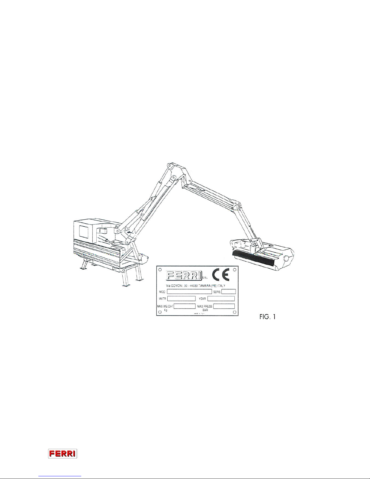
- Identifying the machine sect. 1.2 page 5
- Spare parts sect. 1.3 page 5
TECHNICAL FEATURES sect. 2 page 6
- General description of the machine sect. 2.1 page 6
- Technical specifications sect. 2.2 page 7
- Hydraulic system sect. 2.2.1 page 8
- Noise sect. 2.3 page 9
- Width of cut sect. 2.4 page 9
- Optional equipment sect. 2.5 page 9
- Description of the equipment sect. 2.6 page 10
SAFETY RULES sect. 3 page 12
- General safety rules sect. 3.1 page 12
- Safety rules concerning road traffic sect. 3.2 page 13
- Safety rules during use sect. 3.3 page 13
- Safety rules concerning the hydraulic system sect. 3.4 page 13
- Description and location of safety decals sect. 3.5 page 14
- Driver protection sect. 3.6 page 15
- Danger sect. 3.7 page 15
INSTRUCTIONS FOR INSTALLATION – HANDLING –
PARKING sect. 4 page 16
- Lifting and unloading sect. 4.1 page 16
- Unpacking sect. 4.2 page 16
- Attachment to and detachment from the tractor sect. 4.3 page 16
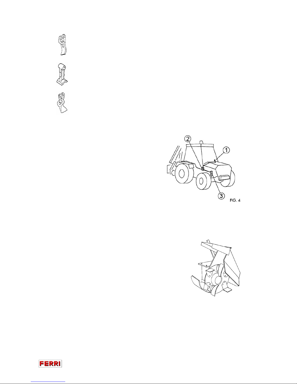
- Electrical connections sect. 4.3.1 page 18
- Assembly instructions sect. 4.3.2 page 18
- Rigid attachment to the tractor sect. 4.3.3 page 20
- Fitting the PTO shaft sect. 4.4 page 21
- Tractor stability sect. 4.5 page 21
- Assembling the flail head sect. 4.6 page 22
- Parking sect. 4.7 page 22
ADJUSTMENT AND SETTING UP sect. 5 page 23
- Regulating the height of cut sect. 5.1 page 23
- Working speed sect. 5.2 page 23
USE AND OPERATING RULES sect. 6 page 24
- Controls sect. 6.1 page 24
- Description of the controls sect. 6.2 page 24
- Starting sect. 6.3 page 25
- Joystick controls sect. 6.4 page 26
- Working mode sect. 6.5 page 27
- Stopping sect. 6.6 page 28
- Transport position sect. 6.7 page 29

3
MACHINE MAINTENANCE sect. 7 page 30
TROUBLE SHOOTING CHART sect. 8 page 31
REPLACING PARTS sect. 9 page 32
- Flail replacement sect. 9.1 page 32
- Pipe replacement sect. 9.2 page 32
- Pin replacement sect. 9.3 page 32
- Oil and filter replacement sect. 9.4 page 32
- Replacing the motor pipes sect. 9.5 page 33
SCRAPPING, SEPARATING THE MATERIALS
AND ELIMINATION sect. 10 page 34

4
WARNING
Before assembling any flail hedge mowers with
electric / electro-hydraulic controls and/or
heat exchanger on the tractor
YOU MUST
read the assembly instructions on the
electrical connections.
Failure to observe the said instructions faithfully may
result in considerable damage to the electrical system,
thereby invalidating the warranty of the same.
Given the importance and sensitivity of the electronics
we recommend that you have the electrical connections
made by a specialized workshop.

5
1 GENERAL INFORMATION
1.1 This operation and maintenance manual is intended for the professional user.
It is mandatory to follow these instructions in order to prevent events which could
endanger the operator’s and other people’s safety, apart from the correct
functioning of the flail-hedge mower. In case of doubt, do not experiment, call
FERRI after-sales service instead, or the specialized FERRI dealer.
1.2 Identifying the machine
Each frame and flail head is fitted with an identification plate; both the data
necessary to identify the model, the serial and part number to order spare parts or
after-sales service, are stamped on the plate (see FIG. 1).
1.3 It is strongly recommended to use genuine FERRI spare parts to avoid altering the
technical features of the flail-hedge mower. FERRI is not responsible for any
damage or injuries to persons or things due to unauthorized modifications.

6
2 TECHNICAL FEATURES
2.1 FERRI flail hedge mowers, from now on called also “machine”, have been designed
to shred materials growing or laying on the ground, e.g. grass, bushes, sticks and
shrubs. Never operate with the flail head lifted off the ground (proper use). Any
other use is considered improper and the manufacturer disclaims all responsibility
for any consequential injuries to person or things or damage to the machine.
“Proper use” also refers to the safety and maintenance rules provided for by the
manufacturer.
Technical names (FIG. 2)
FIG.2
1 - Electro-hydraulic controls
2 – Bonnet
3 - Heat exchanger
4 – Bumper
5 - Flail head control distributor
6 - Hydraulic ram control distributor
7 - Arms rotation hydraulic ram
8 - Arms suspension accumulator
9 - Pump unit
10 – Gearbox
11 - Support feet
12 - Attachment to the tractor
13 - Tourning rest
14 - 1st arm
15 - Hydraulic ram operating parallelogram device
16 - Connecting rod for parallelogram device
17 - 2nd arm
18 - Belt casing
19 - Hydraulic motor
20 - Rear guard
21 - Roller
22 - rotor
23 - Flails
24 - Flail head
25 - Bearing guard
26 - Front guard
27 - Attachment flail head
28 - Transmission rods
29 - Flail head rotation hydraulic ram
30 - Pantograph arm
31 - Transmission support
32 - Control levers (with cables)
33 - 2nd arm hydraulic ram
34 - 1st arm hydraulic rams
35 - Arms rotation accumulator
This machine complies with the following legal provisions:
-89/392/CEE Machines Directive and successive amendments: 91/368/CEE, 93/44/CEE
and 93/68/CEE;
-UNI EN 292/1 and 292/2 (safety of machinery):
-DPR 27 April 1995, No. 547 (regulations for the prevention of accidents at work)

7
2.2 Technical specifications (Tab. 1)
TAB. 1
FLAIL HEDGE MOWER MOD. TKD 54
Min. tractor required power HP (Kw) 90/100 (74/66)
Min. tractor required weight Kg. (lbs) 4400 (9500)
PTO speed rpm 1000
Voltage of the electrical system volt 12
Max. absorbed power HP (Kw) 73 (53)
Standard weight of the machine Kg. (lbs) 1645 (3553)
Attachment to the tractor Cat. II
HYDRAULIC SYSTEM
Hydraulic oil Lt (gal) 105
Intake filter micron 10
Return filter micron 30
Max. arm pressure Bar (PSI) 200 (3300)
Max. flail head pressure Bar (PSI) 280 (4060)
FLAIL HEAD MOD. TNP 125 TNCD 120
Width of cut Cm (in) 125 (49) 110 (43)
Flail head weight Kg. (lbs) 386 (833) 325 (715)
Head movement ° 235°
Rotor speed rpm 3000
Multi-use flails N. 44+22 36+18
Articulated “Y” flails N. 60+30 48+24
Hammer blades N. 22 18

8
2.2.1 Hydraulic system
-Control circuit:
oil supplied by a gear pump is delivered to an electro-hydraulically controlled,
power-assisted distributor. This distributor in this configuartion controls all arm
operations and functions.
Arm movement speed is controlled by a 2-axis joystick, which is powered by a low-
pressure circuit (20 bar). The grip features different buttons which serve to operate
ON/OFF solenoids which in turn operate some of the controls.
The pressure signal sent by the joystick at the distributor inlet is of the proportional
type, thus making for smoother arm movement.
- Power circuit
In this instance the hydraulic system powering the flail hedge mower rotor is of the
closed-circuit hydrostatic type with axial piston pump and motor.
Unlike the open circuit, in which oil flow is broken by the tank, in the closed circuit
the oil flow is continuous because the outlet from the pump goes directly to the
motor and the outlet from the motor goes straight back to the pump.
Closed circuits offer many operational advantages:
-they can stop undamaged under full load with a minimum loss of power
-they accurately maintain a pre-set speed in the presence of resistive or
overwhelming loads
-their output is good, even when subjected to rather demanding duty cycles
-they can operate in two directions at controlled speed, without any major
interference from external loads
-when the control is disengaged, the flail holder shaft remains still
-their response time is faster than any other type of transmission
WARNING:
Frequent checking of the suction filter is recommended. Remember that the
life of hydrostatic transmission strongly depends on the degree of filtering of
the circulating oil!!

9
2.3 Noise
The sound level of this machine, as measured at the operator’s ear, ranges from
75.5 to 79.3 dB when the cab is closed, and from 80 to 85 dB when the rear window
is open. The acoustic power level is 104.5 LWA. When the sound level perceivable
at the operator’s ear ranges from 85 to 90 dB, the use of ear protectors is
recommended.
2.4 Width of cut
Fig. 3 shows the width of cut of the machine.
Dimensions are shown in Table 2.
2.5 Optional equipment
2.5.1 Flails
Depending on the different crops to be cut, the rotor can be changed and suitable
flails can be fitted and used:
- Multi-use flails for grass, shrubs, sticks and bushes up to 5 cm diameter.
N. B.: Do not use on stony ground
- Articulated “Y” flails for grass, shrubs and sticks up to 2 cm diameter.

10
- Hedgtrimming flails for grass or small shrubs up to 1 cm diameter.
- Hammer blades for wood up to 5÷6 cm diameter.
N. B. do not use on stony ground
- Articulated bootie flails for shrubs up to 2 cm diameter.
2.5.2 Locking the front axle of the tractor
(optional)
To increase the stability of the machine
(ONLY WHEN WORKING WITH THE
FLAIL HEDGE MOWER ARM) lock the
front axle of the tractor using switch 1
which controls valve 2which locks
hydraulic ram 3. (FIG. 4)
2.6 Description of the equipment
2.6.1 Ditch cleaners mod. FF45 – FF60 (Fig. 5) to clean
ditches and collect sticks, shrubs and debris (proper
use).
- Range of action, ditch cleaner FF 45 – 0.45 m
- Range of action, ditch cleaner FF 60 – 0.6 m
FIG. 5

11
2.6.2 Cutter bar mod. TR13 – TR22 (FIG. 6) to cut or trim hedges, bushes or branches
(proper use).
- Width of cut TR 13 – 1.3 m
- Width of cut TR 22 – 2.2 m
FIG. 6
NOTE: The above equipment is described in the specific use and maintenance
manuals.
2.6.3 Bank mower mod. SB 45 (FIG. 7) to clear roadside banks, carriageways overgrown
with grass and earth, to open water drainage canals.
FIG. 7
IMPORTANT: if any of the above equipment is fitted on the TKD model fitted with
the pistons pump, contact the “FERRI” TECHNICAL OFFICE.
The above equipment is described in the specific use and maintenance manuals.

12
3 SAFETY RULES
3.1 General safety rules:
- It is mandatory to read and follow the instructions for the use and maintenance
manual before carrying out any operation or move with the machine. Reading it
during the operation is too late. Improper use or an incorrect move may
seriously damage things and people.
- Both the operator and the maintenance fitter must know the machine well,
especially regarding dangers resulting from improper use or incorrect repairs.
- Before starting, checks on tractor and mower must be carried out as regards:
functionality; road safety; accident prevention rules.
- Even when using the machine correctly, stones or other objects may be thrown a
long distance. Therefore nobody must stand within the danger area. Special
attention must be paid when working near roads or buildings.
- Use tractors with cabs.
- The condition of flails and of all guards must be checked before beginning the
daily work. They must be replaced if damaged or missing.
- During checks or repairs, make sure nobody could start the machine by mistake.
- Never wear loose or fluttering clothes.
- Never carry passengers on the tractor.
- Never work, walk or stand under the lifted arm.
- Never use the arm to raise people or objects.
- Never carry people on the mower.
- Never connect the power takeoff with the engine stopped.
- Never approach the machine until the flail holder shaft has completely stopped.
- Do not enter the working zone of the PTO shaft. It is dangerous to approach the
rotating parts of the machine.
- Keep the PTO shaft guard in good order.
- Before starting, check the surrounding area for the likely presence of people
and/or animals.
- Do not stand in the range of operation of the machine.
- The PTO shaft must be assembled and disassembled only with the motor stopped
and the starting key removed.
- Before connecting the power takeoff, check that the speed and the rotational
direction correspond to those of the mower.
- Before leaving the tractor with the machine fitted, proceed as follows:
1 - Inhibit all functions through the machine controls.
2 - Disconnect the power takeoff.
3 - Apply the hand brake and, if the ground is steeply sloping, block the tractor
wheels.
4 - Take the starting key out.
- Immedidately replace any safety sign or missing or damaged decal.
- Never underrate or ignore the safety rules.
-Never use the flail hedge mower in conditions of poor visibility or in blinding
conditions (minimum recommended visibility distance is 50 metres).
Always inspect the area before starting work, removing any potentially dangerous
materials beforehand.
-Never continue to work when material has become rolled up on the flail holder
shaft.
-Always use mechanical and/or visual warning devices where necessary

13
-Make sure that no unauthorized persons enter the work area at any time.
No-one should come within a distance of 50 metres when the mower is in
operation.
3.2 Safety rules concerning road traffic
- Disconnect the power takeoff.
- In transport, reduce speed, especially on bumpy roads. The very weight of the
machine alters the stability and may render driving difficult and damage the
machine itself.
- When driving on public roads, observe all road regulations.
- Never transport the mower with the moving flail holder shaft, even for short
distances.
- Protect the control lever of the mower against accidental blows.
- Lock the arm and the flail head, as indicated in the sect. 6.5.
3.3 Safety rules during use
- Pay special attention, when working with the machine, not to touch fixed objects,
such as road drain wells, shafts, kerbs, guard rails, tracks, etc. This could cause
the breakage of the flails, which would be thrown at very high speed.
- If wires, ropes or chains should get entangled in the rotor, stop immediately, to
prevent damage or dangerous situations; stop the rotor and the tractor, take the
starting key out.
- Put working gloves on, clear the rotor with the aid of pliers or shears. Do not try to
disentagle by inverting the rotational direction of the rotor.
- Do not use the machine when there is vibration in the flail head, as this would
cause breakages and serious damage. Find the cause of the vibration and
eliminate it.
- Do not operate with the arm in extension if the tractor is on a sloping ground.
3.4 Safety rules concerning the hydraulic system
- Stop immediately in case of oil leaks.
IMPORTANT: do not look for oil leaks with bare
hands, but always with the aid of a cloth. Oil under
strong pressure may seep into the skin causing
serious infections. In this case contact a doctor
immediately.
- Periodically check the flexible pipes; if they are
worn or damaged they must be replaced with
others of the same specification.
- Before working on the hydraulic system, lower the
flail head, stop the tractor, exhaust all pressure of
the hydraulic system and the arm safety
accumulator (FIG. 8) using all control levers in both
directions.
- Close the accumulator tap for the hydropneumatic
suspension of the arms, shift the lever from A to B (FIG. 9).

14
- Used oils and greases must be stored and disposed according to antipollution
rules.
3.5 Description and location of safety decals (FIG. 10)
Carefully follow the instructions given on the decals.
Description of the decals
1 - Warning of danger through lack of knowledge of all the functions of the
machine and the resulting risks. Read the use and maintenance manual
before operating the machine.
2 - Danger sign of crushing or shearing: do not put limbs in the moving parts of
the machine with this decal.
3 - Danger sign; it shows the risk of flying stones or other objects and makes it
mandatory to keep out of the danger zone.
4 - Danger sign of rotating flails; do not enter their area of operation with hands or
feet.
5 - Danger of getting entangled. Do not approach the rotating PTO shaft. Pay
special attention to clothes, which must not be loose or fluttering.

15
3.6 Driver protection
- In order to protect the operator from possible flying debris, it is recommended to fit
two protection grills (1) to the operator’s cab, so that the debris thrown by the
machine cannot reach the glass of the cab and break it causing injuries to the
operator (FIG. 11)
FIG. 11
- It is recommended to fit 5 mm sheets of polycarbonate (2) between the grills (1)
and the glass. They will prevent small stones and fragments from hitting the glass
of the cab. (FIG. 11)
- Attach the flail hedge mower only to tractors with type approved anti-roll
over driving cab (ROPS).
- The operator and all personnel must wear a safety helmet and eye protectors as
protection against possible flying material.
3.7 Danger
- Pay special attention when working under or near electric lines, an electric arc can
be released. (FIG. 12)
FIG. 12

16
4 INSTRUCTIONS FOR INSTALLATION – HANDLING - PARKING
4.1 Lifting and unloading
To handle the flail hedge mower, use a hoist or a crane with lifting capability
suitable to the weight of the machine (see TAB. 1) and with proper chains and type
approved hooks to be fixed in the marked points, as shown in FIG. 13. This can be
done with a lift truck, first close the arms and fix them to the frame with a chain.
4.2 Unpacking
- In order to transport it, the mower can be supplied in a special pack (disassembled
and on pallets).
In this case, a card showing the reassembling procedure will be attached to the Use
and Maintenance manual.
4.3 Attachment to and detachment from the tractor
Before carrying out this operation and any time the machine is used, it is mandatory
to:
- Visually check the machine in general
- Check that all guards are fitted and in good condition
- Confirm that all flails are fitted and in good condition
- Grease the bearings and any other parts as indicated by a decal (FIG. 42)

17
- Check the oil level of tank and gearbox
- Check that all hydraulic pipes are in good condition, look for signs of leakage
beneath the machine
- Check that the number of revolutions and the rotational direction of the power
takeoff correspond to those required by the flail hedge mower (FIG. 14)
-
- To attach the machine to the tractor (FIG. 15), bring the 2 arms of the tractor
hydraulic lifter (1) near the flail hedge mower, to the points corresponding to the
pins.
- Insert the pins (2) and secure them with the spring clips.
- Fit the 3rd point stabilizer (3), raise the machine until the power takeoff is at the
same heigh of the tractor PTO and adjust the linkage stabilizer until the
perpendicularity with the ground is reached. Stiffen the 2 lifter arms by
correspondent linkage stabilizers (4) thus fixing the machine in a central position.
Fix the stabilizers (5) to the tie plate (6) (different from tractor to tractor).
- Proceed in reverse order to detach the flail hedge mower from the tractor.
IMPORTANT: Never operate the tractor hydraulic lift when additional stabilizers
are fitted (6).

18
4.3.1 Electrical connections
Important notice
All flail hedge mowers with electrically/electro-hydraulically controlled distributors
(low pressure) and/or heat exchanger, are equipped with electric cables whose
wires are coloured as per current laws in force (see fig. A) (blue: positive pole (+)
fixed to connector no. 58; brown: negative pole (-) fixed to connector no. 31) and
of suitable thickness (heat exchanger wire thickness: 2x6 mm2; control box wire
thickness: 2x2.5 mm2) .
Also, to prevent the inversion of polarity near the terminals, the wires are tagged
with plastic rings bearing the symbols (+) and (-).
When making the connections it is vitally important
NOT TO INVERT THE POLARITY
and
NOT TO ALTER THE WIRE THICKNESS
(risk of burning the electronic components )
4.3.2 Assembly instructions
After having performed the operations as described in section 4.3, to make the
electrical connections proceed as follows: (see fig. A)
1st case: flail hedge mower with electric controls + heat exchanger
-fix sockets Aand Bin the rear part of the tractor frame
Cable (D) (supplies the exchanger (3) and is supplied by Ferri)
-take cable (D) to the tractor battery
-connect the blue wire of cable (D) to the positive pole (+) of the battery
-connect the brown wire of cable (D) to the negative pole (-) of the battery
Cable (C) (supplies the electrical control box (4) and is not supplied by Ferri)
-connect the socket (B) to the battery, (already fixed to the rear part of the tractor)
using cable (C), (to be installed by the customer) of thickness 2.5 mm2, taking care
to make the connections as shown in fig. A, i.e.:
-connect connector no. 58 (positive +) (blue wire) of the socket (B), to the
positive pole of the battery
-connect connector no. 31 (negative -) (brown wire) of the socket (B), to the
negative pole of the battery.
2nd case: flail hedge mower with electrical controls only (no heat exchanger)
WARNING: cable (C) which supplies the electrical control box is not supplied by
Ferri, but must in any case be installed by the customer.
Cable (C)
-fix the socket (B) to the rear part of the tractor frame
-connect the socket (B) to the tractor battery using a cable (C) of thickness 2.5
mm2, taking care to carry out the connections as shown in figure A, i.e.:
-connect connector no. 58 (positive +) (blue wire) of the socket (B), to the
positive pole of the battery

19
-connect connector no. 31 (negative -) (brown wire) of the socket (B), to the
negative pole of the battery.
Once the connections have been made, before tensioning the electrical system
make sure that:
-the connections have been made as shown in fig. A
-the battery terminal boards are securely tightened
-there are no bare wires
FIG. A
1 Electric fan
2 Thermostat
3 Exchanger electrical box
4 Distributor electrical box
5 Tractor battery
Brown wire
CABLE
CABLE
Brown wire
Brown
wire
Blue wire
Blue
wire
Blue
wire
From Flail hedger mower
To be fixed to the tractor
To the battery

20
4.3.3 Rigid attachment to the tractor: (FIG. 16) optional
The machine can be fitted to the tractor with rigid couplings if the arms 1 (FIG. 15)
of the tractor hydraulic lift does not guarantee enough rigidity or cannot support the
weight of the flail hedge mower, see data given in FIG. 17.
If the above coupling is not fitted by the FERRI Company, the customer must get in
touch with a specialised workshop.
- Before fitting the flail hedge mower to the tractor, verify that the overturning
moment of the arm is compatible with that allowed by the tractor. FIG. 17 shows
the weight and the position of the centre of gravity with the arm fully extended.
This manual suits for next models
1
Table of contents
Other FERRI Lawn Mower manuals
Popular Lawn Mower manuals by other brands

Wolf Garten
Wolf Garten LI-ION POWER GT 815 Original operating instructions

Ransomes
Ransomes 51 Super Certes Safety, operation & maintenance manual

Craftsman
Craftsman EZ3 917.271011 owner's manual

MTD
MTD 114-050-000 owner's manual

Murray
Murray 7800889 Operator's manual

Snapper
Snapper 1690769 Operator's manual