ferroamp Pylontech M1 User manual

Installation manual
Pylontech M1

Innehållsförteckning / Table of contents
1. SVENSKA ............................................................................................................................................................................................................................. 2
1Introduktion........................................................................................................................................................................................................................ 2
1.1 Ingående artiklar ...................................................................................................................................................................... 2
1.2 Kabelförteckning ...................................................................................................................................................................... 2
1.3 Dimensioner .............................................................................................................................................................................. 2
1.4 Varningar och förbehåll........................................................................................................................................................... 2
1.5 Förklaring av säkerhetsaviseringar........................................................................................................................................ 2
2Installation.......................................................................................................................................................................................................................... 3
2.1 Placering.................................................................................................................................................................................... 3
2.2 Förberedelser inför installation ............................................................................................................................................. 3
2.3 Inkoppling av batterimoduler................................................................................................................................................. 4
2.4 Anslutning till likspänningsnät.............................................................................................................................................. 9
3Drift ....................................................................................................................................................................................................................................... 9
4Urkoppling .......................................................................................................................................................................................................................... 9
5Felsökning........................................................................................................................................................................................................................... 9
2. ENGLISH.............................................................................................................................................................................................................................11
6Introduction......................................................................................................................................................................................................................11
6.1 Included items ........................................................................................................................................................................11
6.2 Cable list ..................................................................................................................................................................................11
6.3 Dimensions..............................................................................................................................................................................11
6.4 Warnings and reservations ...................................................................................................................................................11
6.5 Explanation of safety notices ...............................................................................................................................................11
7Installation........................................................................................................................................................................................................................12
7.1 Placement................................................................................................................................................................................12
7.2 Preparations before installation ..........................................................................................................................................12
7.3 Installation of battery modules............................................................................................................................................13
7.4 DC nanogrid connection ........................................................................................................................................................18
8Operations.........................................................................................................................................................................................................................18
9Disconnection..................................................................................................................................................................................................................18
10 Troubleshooting .................................................................................................................................................................................................................18
Revision history
Date
Revision
2022-01-28
A1
PN: PD10010, Copyright Ferroamp Elektronik AB 2022. Document subject to change without prior notice.
Verify that you have the latest version of this manual on our website. www.ferroamp.com/downloads

2
1. SVENSKA
1Introduktion
I detta häfte finner du anvisningar för installation av ert
Pylontech M1-batteri. Se till att läsa instruktionen noggrant för
att undvika onödiga fel.
1.1 Ingående artiklar
Följande artiklar ingår vid leverans av ett Pylontech M1:
Artikel
Antal
Pylontech M1 rackskåp med tillbehör
1
Pylontech kontrollmodul
1
Batterimodul Pylontech H32148
19
ESO-distribution
1
ESO
6
Frontplåt ESO:er
1
Täckplåt
1
Fästskruv frontplåt –ESO:er
24
Fästskruv frontplåt - rackskåp
6
Fästskruv ESO-distribution - rackskåp
6
Fästskruv täckplåt - rackskåp
4
Korgmutter
16
Ethernetkabel sammankoppling ESO:er
5
CAN-kommunikationskabel ESO -
kontrollmodul
1
Pylontech kablage (se kabelförteckning)
Övriga Pylontech-artiklar (se manual från
Pylontech)
1.2 Kabelförteckning
Beskrivning
Antal
Beteckning
Kabel för seriekoppling av
batterimoduler (Svart-Orange)
18
DC-kabel typ A
DC+ kabel Batterimoduler –
Kontrollmodul (Orange)
1
DC-kabel typ B
DC- kabel Batterimoduler –
Kontrollmodul (Svart)
1
DC-kabel typ C
DC+ kabel Kontrollmodul –
ESO-distribution (Orange)
1
DC-kabel typ D
DC- kabel Kontrollmodul –
ESO-distribution (Svart)
1
DC-kabel typ E
CAN-kommunikationskablar
19
Kommunikations
kabel
AC-kabel Kontrollmodul 230 V
1
AC-kabel
1.3 Dimensioner
Färdigmonterat Pylontech M1
-Mått (H x B x D): 2130 x 815 x 659 mm
-Vikt: 1036 kg
Pylontech batterimodul
-Mått (H x B x D): 150.5 x 330 x 628 mm
-Vikt: 48 kg
1.4 Varningar och förbehåll
UPPMANING! Använd endast denna produkt enligt angivna
instruktioner för att undvika eventuella faror.
VARNING! Batteriet får inte öppnas av obehörig personal.
Kontakta återförsäljare vid behov av service.
VARNING! Den elektriska installationen skall utföras av behörig
installatör och i enlighet med gällande elektrisk standard och
säkerhetsföreskrifter.
VARNING! Du får ej ansluta enheter till likspänningsnätet när
det är spänningssatt.
VARNING! Risk för elektrisk stöt och ljusbåge om produkten inte
hanteras i enlighet med manualens instruktioner.
VARNING! Använd inte produkten om du misstänker skada eller
lösa föremål inuti produkten. Låt den inspekteras av kvalificerad
personal före användning.
VARNING! Använd inte produkten om hela eller del av
kapslingen är borta, till exempel vid reparation, rör inte utsatta
delar.
NOTERA! Garantin gäller ej om produkten modifierats eller inte
installeras i enlighet med denna manual.
1.5 Förklaring av säkerhetsaviseringar
Blixtsymbolen i en liksidig triangel varnar för
farlig spänning.
Utropstecknet i en liksidig triangel är avsedd att
varna användaren om att vårdslöshet av denna
information kan vara livshotande!
Utropstecknet i en cirkel är avsett att informera
användaren om att försummelse av denna
information kan vara förknippad med kroppsskada
och / eller skada på produkten.

3
2Installation
Installationsguiden kommer att ta dig genom hela processen steg
för steg. Placering, montering av batterimoduler, kontrollmodul
samt ESO:er och anslutning till likspänningsnätet.
NOTERA! För att få en bra överblick av installationsprocessen
rekommenderar vi att läsa igenom samtliga instruktioner innan du
sätter igång.
2.1 Placering
Batteriet är IP20-klassat och ska placeras i ett utrymme som
uppfyller följande kriterier.
-Inomhusmiljö med skydd från direkt solljus och regn
-Omgivningstemperaturen får inte understiga 0 °C och
inte överstiga 40 °C
-Miljön ska vara icke-kondenserande, den relativa
luftfuktigheten skall vara under 95%
NOTERA! För att underlätta installation och service
rekommenderar vi att batteriet placeras med ett fritt utrymme
framför rackskåpet på 1 m samt ca 40 cm på vardera sida om
rackskåpet.
2.2 Förberedelser inför installation
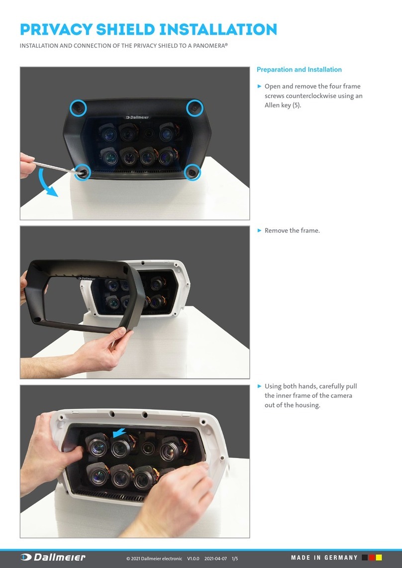
1. Avlägsna de tre översta planen i den högra halvan av rackskåpet.
2. Montera de tre nya planen längst upp i den vänstra halvan av
rackskåpet. Avståndet mellan planen ska vara detsamma som
mellan övriga plan i rackskåpet.
•Arbeta inte ensam. I en nödsituation kan en
annans närvaro vara nödvändig!
•Elinstallationen måste uppfylla nationella /
lokala lagar och förordningar, lämpliga
standarder och tillämpliga krav från erkända
organisationer.
•Den elektriska installationen skall utföras av
behörig installatör och i enlighet med
gällande elektrisk standard och
säkerhetsföreskrifter.
•Se till att placeringen av Pylontech M1 aldrig
utgör ett hinder för nödutrymning, i enlighet
med nationell och lokal lagstiftning.

4
3. Dra DC-kabel typ D och DC-kabel typ E ut genom den vänstra
öppningen i toppen av rackskåpet och för sedan in kabeln genom
den högra öppningen. Dra även ut AC kabel till kontrollmodulen
genom den vänstra öppningen.
4. Koppla bort de förmonterade adaptrarna från baksidan av alla
ESO:er enligt bilden ovan.
2.3 Inkoppling av batterimoduler
1. Placera Pylontech SC100 Controller i facket längst upp till
vänster i rackskåpet enligt bilden (bortse från kablarna). Fäst med
avsedda skruvar i fästskenor.
2. Placera och montera Pylontech-batterimoduler i resterande fack
i rackskåpet.

5
3. Koppla samman batterimoduler på vänster halva av rackskåpet
med DC-kablar typ A.
4. Koppla samma batterimoduler med kommunikationskablar
enligt bilden ovan.
5. Koppla samman de två nedersta batterimodulerna med DC-kabel
typ A enligt bilden ovan.
6. Koppla samman de två nedersta batterimodulerna med
kommunikationskabel enligt bilden ovan.
7. Koppla samman övriga batterimoduler på högra halvan av
rackskåpet med DC-kablar typ A enligt bilden ovan.
8. Koppla samman övriga batterimoduler på högra halvan av
rackskåpet med kommunikationskablar enligt bilden ovan.
9. Kontrollera att batterimoduler är korrekt inkopplade genom att
mäta spänningen mellan plus- och minuspolerna enligt bilden
ovan. Spänningen bör vara över 600 V (32 V per modul).

6
10. Anslut DC-kabel typ D i kontakten DC+ och DC-kabel typ E i
kontakten DC- enligt bilden ovan.
11. Koppla samman den översta batterimodulen och Pylontech
kontrollmodul med en kommunikationskabel enligt bilden ovan
12. Anslut CAN-kommunikationskabel ESO - kontrollmodul i
CAN/Link port B enligt bilden ovan
13. Säkerställ att Pylontech kontrollmodul är avslagen och anslut
AC-kabel enligt bilden ovan.
14. Kontrollera att DIP-switchar på kontrollmodulen står i rätt läge
enligt bilden ovan.
15. Montera korgmutter för ESO-distribution i hål nr 2, 12 och 15
(räknat uppifrån) på raderna närmast gavlarna på höger sida av
rackskåpet.
16. Fäst ESO-distributionen på höger insida av rackskåpet enligt
bilden ovan.
NOTERA placering av kopplingsplint för DC-kabel typ D, DC-kabel
typ E samt kopplingsplint för DC-kabel till DC-nät på bilden nedan
(DC+, DC- och PE).

7
17. Säkerställ att DC-nätet är spänningslöst samt att Pylontech
SC100 Controller är avstängd. Anslut sedan DC-kabel typ D och DC-
kabel typ E samt DC-kabel till DC-nät till respektive kopplingsplint
enligt bilden ovan.
18. Anslut ESO 1 till en adapter från ESO-distributionen. Anslut
CAN kommunikationskabeln från Pylontech kontrollmodulen
NOTERA den röda tvinnade Pre Charge-kabeln som är ansluten till
3 av 6 adaptrar. Dessa 3 adaptrar ska anslutas till ESO nr. 1,3 och
5.
19. Anslut ESO 2 till en adapter utan Pre Charge-kabel. Koppla
sedan samman ESO 1 och ESO 2 med en ethernetkabel enligt
bilden ovan.
Eternetkablen ansluts i den högra ingången på ESO 1 och på den
vänstra ingången på ESO 2. Säkerställ även att de svarta DIP-
switcharna på ESO:n står i rätt läge enligt bilden.
20. Anslut resterande ESO:er till resterande adaptrar från ESO-
distributionen, koppla samman dem med ethernetkablar i
nummerordning precis som med ESO 1 och 2. Bilden ovan
illustrerar sammankopplingen av ESO:er med ethernetkablar sett
bakifrån.

8
21. Säkerställ att alla DIP-switchar på baksidan av ESO:erna står i
rätt läge och placera sedan ESO:er enligt bilden ovan.
22. Montera korgmutter för ESO-distribution i hål nr 3, 11, 13, 25
och 37 enligt bilden ovan.
23. Drag ut ESO:erna cirka 5cm ur skåpet och montera sedan
frontplåten enligt bilden ovan.
24. Placera ESO:erna så att frontplåten ligger mot listerna på
rackskåpet och fäst sedan frontplåten i de förberedda
korgmuttrarna. Fäst sedan täckplåten ovanför frontplåten
enligt bilden ovan

9
25. Koppla samman batteristrängen med Pylontech SC100
Controller med DC-kabel typ B och DC-kabel typ C enligt bilden
ovan.
2.4 Anslutning till likspänningsnät
NOTERA! Vi rekommenderar att använda ändhylsor för samtliga
anslutningspunkter som har mångtrådiga ledare.
1. För att beräkna korrekt kabeldimension, använd Ferroamps
kabelkalkylator som finns tillgänglig på www.ferroamp.se
under supportfliken (max spänningsfall är 1% mellan batteri
och EnergyHub).
2. DC-kabeln som ansluter ESO-distributionen till
likspänningsnätet leds ut på baksidan av rackskåpet.
3. Avsäkra L+ och L- ledarna.
4. Se Commissioning guide för instruktioner om generell
drifttagning av batterier i EnergyHub-systemet.
NOTERA! Skador på produkten som uppkommer vid felaktig och
vårdslös inkoppling tar Ferroamp ej ansvar för.
3Drift
Det är viktigt att batteriet används och/eller motioneras
regelbundet. Om batteriet står oanvänt under en längre period kan
självurladdningen leda till att battericellerna laddas ur helt. Detta
är något som litiumjoncellerna kan ta skada av.
4Urkoppling
Vid urkoppling av ett Pylontech M1 se till att följande steg
efterföljs:
1. Stäng av likspänningsnätet samt öppna brytaren i den
DC-fördelningen som batteriet är anslutet till.
2. Slå av Pylontech Kontrollmodulen genom att trycka på
den röda knappen.
3. Koppla ur AC-kabeln ur 230V vägguttag
4. Koppla bort Kontrollmodulen från ESO-distributionen
5. Koppla bort battericellerna från kontrollmodulen
6. Koppla bort batterimodulerna
5Felsökning
När EnergyHub och likspänningsnätet slås på identifierar
EnergyHub automatisk alla anslutna batterier. Denna process kan
ta upp till 10 minuter. Om ett batteri inte hittas kan detta bero på
något av följande:
●Trasiga säkringar eller öppna brytare mellan EnergyHub och
Batteri
Kontrollera säkringar och brytare.
●Batteri anslutet efter att EnergyHub har kört sin
uppstartssekvens och batteri har ej lagts till i systemtopologi.
Tryck in resetknappen på EnergyHub i 10 sekunder.
Anslut INTE batteriet till likspänningsnätet om
likspänningsnätet är spänningssatt.
Pylontech M1 måste avsäkras mot
likspänningsnätet med 60A säkring med GPV
karakteristik.

10

11
2. ENGLISH
6Introduction
In this booklet you will find instructions for installing your
Pylontech M1 battery. Be sure to read the instructions carefully to
avoid unnecessary errors.
6.1 Included items
The following items are included in the delivery of a Pylontech M1:
Article
Quantity
Pylontech M1 cabinet
1
Pylontech control module
1
Battery module Pylontech H32148
19
ESO distribution
1
ESO
6
Front plate ESOs
1
Cover plate
1
Mounting screw front plate - ESOs
24
Mounting screw front plate - cabinet
6
Mounting screw ESO distribution -
cabinet
6
Mounting screw cover plate - cabinet
4
Cage nut
16
Ethernet cable interconnection ESOs
5
CAN communication cable ESO - control
module
1
Pylontech cabling (see cable list)
Other Pylontech articles (see manual
from Pylontech)
6.2 Cable list
Description
Quantity
Designation
Cable for series connection
of battery modules (Black
Orange)
18
DC cable type A
DC + cable Battery modules
- Control module (Orange)
1
DC cable type B
DC cable Battery modules -
Control module (Black)
1
DC cable type C
DC + cable Control module -
ESO distribution (Orange)
1
DC cable type D
DC cable Control module -
ESO distribution (Black)
1
DC cable type E
CAN communication cable
19
Communication
cable
AC cable Control module
230 V
1
AC-cable
6.3 Dimensions
Assembled Pylontech M1
-Dimensions (H x W x D): 2130 x 815 x 659 mm
-Weight: 1036 kg
Pylontech battery module
-Dimensions (H x W x D): 150.5 x 330 x 628 mm
-Weight: 48 kg
6.4 Warnings and reservations
RECOMMENDATION! Only use this product according to the
instructions supplied to avoid any danger.
WARNING! SSO may not be opened by unauthorized personnel.
Contact your reseller if you need service.
WARNING! The electrical installations shall be conducted by
authorized personnel and in accordance with local and national
electrical standards and safety measures.
WARNING! You are not allowed to connect units to the DC nanogrid
when it is energized.
WARNING! Risk of electrical shock/arc if the product is not used
according to the instructions in the manual.
WARNING! Do not use the product if you suspect the product is
damaged or you find loose items in the product. Let it be inspected
by qualified personnel before use.
WARNING! Do not use the product if the housing has been
tampered with or not intact, for example during repair, do not
touch exposed parts.
NOTE! The warranty does not apply if the product has been
modified, tampered with, or not installed in accordance with this
manual.
6.5 Explanation of safety notices
The flash symbol in an equilateral triangle warns
of dangerous voltage.
The exclamation mark in an equilateral triangle is
intended to warn the user that negligence of this
information can be life threatening!
The exclamation mark in a circle is intended to
inform the user that neglect of this information
may be associated with body injury and / or
damage to the product.

12
7Installation
The installation guide will take you through the entire process step
by step. Location, installation of battery modules, control module
and ESOs and connection to the DC network.
NOTE! To get a good overview of the installation process, we
recommend that you read all the instructions before you start.
7.1 Placement
The battery is IP20 rated and must be placed in a room that meets
the following criteria.
NOTE! Ferroamp does not take responsibility for installations
where the following stated criteria are not met.
-Indoor environment with protection from direct sunlight
and rain
-The ambient temperature must not fall below 0° C and
not exceed 40° C
-The environment must be non-condensing, the relative
humidity must be below 95%
NOTE! To facilitate installation and service, we recommend that
the battery is placed with a free space in front of the cabinet of 1
m and a free space of about 40 cm on each side of the rack cabinet.
7.2 Preparations before installation
1. Remove the top three shelfs in the right half of the cabinet.
2. Mount the three new shelfs at the top of the left half of the rack
cabinet. The distance between the shelfs must be the same as
between the other shelfs in the rack cabinet.
•Do not work alone. In an emergency,
someone else's presence may be necessary!
•The electrical installation must comply with
national / local laws and regulations,
appropriate standards, and applicable
requirements from recognized organizations.
•The electrical installation must be carried
out by a qualified installer and in accordance
with the applicable electrical standard.
•Ensure that the Pylontech M1 placement
never becomes an obstacle to a emergency
evacuation path.

13
3. Route DC cable type D and DC cable type E through the left
opening in the top of the cabinet and then insert the cable through
the right opening. Also route the AC cable to the control module
through the left opening.
4. Disconnect the pre-assembled adapters from the back of all ESOs
as shown above.
7.3 Installation of battery modules
1. Place the Pylontech SC100 Controller in the compartment at the
top left of the cabinet as shown (disregard the cables). Fasten with
the intended screws in the mounting rails.
2. Place and fasten Pylontech battery modules in the remaining
compartments in the rack cabinet.

14
3. Connect battery modules on the left half of the rack cabinet with
DC A type cables as shown above.
4. Connect battery modules with communication cables as shown
above.
5. Connect the two lower battery modules with DC cable type A as
shown above.
6. Connect the two battery modules at the bottom with a
communication cable as shown above.
7. Connect the battery modules on the right half of the cabinet with
DC cables type A as shown above.
8. Connect the battery modules on the right half of the cabinet with
communication cables as shown above.
9. Check that the battery modules are connected correctly by
measuring the voltage between the positive and negative poles as
shown above. The voltage should be above 600 V (32 V per
module).

15
10. Connect DC cable type D to the DC + connector and DC cable
type E to the DC- connector as shown above.
11. Connect the top battery module and the Pylontech control
module with a communication cable as shown above
12. Connect CAN communication cable ESO - control module in
CAN / Link port B as shown above
13. Make sure that the Pylontech control module is switched off
and connect the AC cable as shown above.
14. Check that the DIP switches on the control module are in the
correct position as shown above.
15. Install cage nuts for ESO distribution in holes no. 2, 12 and 15
(counted from above) on the rows closest to the gables on the right
side of the rack cabinet.
16. Attach the ESO distribution to the right inside of the rack
cabinet as shown above.
NOTE placement of terminal block for DC cable type D, DC cable
type E and terminal block for DC cable to EnergyHub in the picture
below (DC +, DC- and PE).

16
17. Make sure that the DC network is de-energized and that the
Pylontech SC100 Controller is switched off. DC cable type D and
DC cable type E and the DC cable to the EnergyHub in the terminal
blocks as shown above.
18. Connect ESO 1 to an adapter from the ESO distribution. Connect
the CAN communication cable from the Pylontech control module
NOTE the red twisted Pre Charge cable connected to 3 of 6
adapters. These 3 adapters must be connected to ESO no. 1,3 and
5.
19. Connect ESO 2 to an adapter without a Pre Charge cable. Then
connect ESO 1 and ESO 2 with an Ethernet cable as shown above.
The Ethernet cable is connected in the right input on ESO 1 and in
the left input on ESO 2. Also make sure that the black DIP switches
on the ESO are in the correct position as shown above.
20. Connect the remaining ESOs to the remaining adapters from
the ESO distribution, connect them with Ethernet cables in
numerical order just as with ESO 1 and 2. The picture above
illustrates the connection of ESOs with Ethernet cables seen from
behind.

17
21. Make sure that all DIP switches on the back of the ESOs are in
the correct position and then place the ESOs as shown above.
22. Install cage nuts for the ESO front plate and the cover plate in
holes no. 3, 11, 13, 25 and 37 as shown above.
23. Pull the ESOs about 5 cm out of the cabinet and then
mount the ESO front plate as shown above.
24. Position the ESOs so that the front plate rests against the
strips on the rack cabinet and then fasten the front plate to
the prepared cage nuts. Then attach the cover plate above the
front plate as shown above

18
25. Connect the battery string with the Pylontech SC100 Controller
with DC cable type B and DC cable type C as shown above.
7.4 DC nanogrid connection
NOTE! We recommend using end sleeves for all connection points
that have multi-wire conductors.
1. To calculate the correct cable dimension, use Ferroamp's cable
calculator which is available at www.ferroamp.se under the
support tab (maximum voltage drop is 1% between battery and
EnergyHub).
2. The DC cable that connects the ESO distribution to the DC
network is routed to the back of the cabinet.
3. Fues L+ and L-.
4. See the Commissioning Guide for instructions on general battery
operation of the EnergyHub system.
NOTE! Damage to the product that occurs in the event of incorrect
and negligent handling, is not the responsibility of Ferroamp.
8Operations
It is important that the battery is used and / or exercised regularly.
If the battery is left unused for a long period, the self-discharge can
lead to the battery cells being completely discharged. This is
something that lithium-ion cells can damage.
9Disconnection
When disconnecting a Pylontech M1, make sure that the following
steps are followed:
1. Switch off the mains supply and open the switch in the DC
distribution to which the battery is connected.
2. Switch off the Pylontech Control Module by pressing the red
button.
3. Disconnect the AC-cable from the 230V socket.
4. Disconnect the Control Module from the ESO distribution
5. Disconnect the battery cells from the control module
6. Disconnect the battery modules
10 Troubleshooting
When EnergyHub and the DC network are turned on,
EnergyHub automatically identifies all connected batteries.
This process can take up to 10 minutes. If a battery is not
found, it may be due to one of the following:
●Broken fuses or open switches between EnergyHub and
Battery
Check fuses and switches.
●Battery connected after EnergyHub has run its boot sequence
and no battery has been added to the system topology.
Press the reset button on the EnergyHub for 10 seconds.
Do NOT connect the battery to the DC nano grid if
the DC nano grid is energized
Pylontech M1 must be fused of towards the DC nano
grid with fuse of 60A with gPV characteristics.

Electricity.
Reinvented.
Table of contents
Languages:
