Ferve F-1860 User manual

1
FERVE F-1860
WARNING
♦ Engines produce carbon monoxide which is odourless, causes slower
reaction time, and can lead to serious injury through inhalation. Keep service
areas WELL VENTILATED while the engine is running!
♦ Activate the handbrake and block the wheels be ore testing or repairing the
vehicle. It is especially important to block the wheels on ront-drive vehicles,
as the handbrake does not lock the drive wheels.
♦ Wear an eye shield when testing or repairing vehicles. Exceeding the limits
o the F-1860 is dangerous. It will expose you to serious or possibly atal
injury. Care ully read and take heed o the precautions described in this
instruction manual, and make sure that the established limits o the F-1860
are never exceeded.
♦ Under absolutely no circumstances must voltage exceed 1000 VDC or 750
VDC between any terminal or ground.
♦ Extreme caution must be exercised when measuring voltage above 25 VAC
or VDC.
♦ Circuits to be tested must be protected by a 20A use or circuit breaker.
♦ Do not use the F-1860 i it has been damaged.
♦ Do not use the test leads i the insulation is damaged or the cable is
exposed.
♦ Use adequate current clamps when measuring circuits in excess o 10A.
♦ To avoid electrical shock, never touch the test leads, tips or circuit while
testing.
♦ Do not make a voltage measurement with the test leads in the 20A or mA
terminal.
♦ When testing or voltage or current, make sure that the corresponding
unction o the F-1860 is the correct one. We recommend you take a test
reading o a known voltage or current be ore carrying out a speci ic unction.
♦ Choose the proper range and unction or the measurement. Do not try to
take voltage or current measurements that may exceed the ratings marked
on the unction /range switch or terminal.
♦ When measuring current, connect the F-1860 in series with the load.
♦ Never connect more than one set o leads to the F-1860.
♦ Disconnect the live test lead be ore disconnecting the common test lead
(COM).
♦ The mA and 20A terminals are protected by uses. In order to avoid possible
injury or damage, use only in circuits not exceeding 400mA, 10A continuous
or 20A or a maximum15 seconds.
IMPORTANT
♦ In order to maintain the accuracy o the F-1860, replace the battery as soon
as the battery symbol appears on the display.
♦ Avoid measuring errors rom external inter erence: keep the F-1860 away
rom spark plug cables or wire coils.

2
♦ Avoid damage to the F-1860 when testing: disconnect the test leads rom
the test points be ore changing unctions.
♦ Do not exceed the limits shown in the table below:
Function Terminal Input Limit
AC Volts 750 V AC rms
DC Volts V/ Ω / RPM 1000 V DC
Frequency
Ohm (resistance)
Diode
V/ Ω / RPM 500 V AC/DC
AC/DC 400 mA mA 400 mA AC/DC
AC/DC 20 A 20 A *20 A AC/DC
RPM
Duty Cycle (%)
Dwell angle
V/ Ω / RPM 500 V AC/DC
*10A continuous measurement or 20A or a maximum15 seconds
Ohms cannot be measured when voltage is present. They can only be
measured in a non-powered circuit. However, the F-1860 is protected up to
500V.
MEASURING BASICS
Protecti e Rubber Casing
The rubber casing has been designed to protect the F-1860 when accidentally
dropped. Additionally, it provides a convenient storage method or the test
probes. It is also use ul or holding one o the test probes, while leaving another
hand ree to operate the other test probe while holding the F-1860 in the other
hand. (see igure x).

3
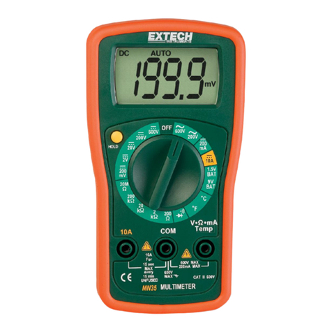
1. Digital and Analogue Display
Display eatures:
a. Four character digital display
b. Symbols indicating unctions
c. Analogue bar graph
2. Function buttons
Press the button to select the desired unction. A
symbol con irming your selection will appear.
3. Rotary Selector Switch
Use this switch to select a unction or to turn o
the F-1860.
4. Temperature terminal
Insert the temperature probe into this terminal.
5. Test lead terminals
The black (-) test lead is used in the COM terminal
or all tests. The red (+) test lead is used to
measure Amps or Volts.
Automatic Deactivation eature
♦ Automatic Power O a ter 30 minutes o inactivity.
♦ Automatic Power can be disactivated. This eature must be set when the
F-1860 is to record data over a period o time in excess o 30 minutes. In
order to disactivate the “Power O ” mode, keep the yellow “PWR RST”
button pressed while switching on the F-1860.
Digital and Analogue Display
∗ Press HOLD to maintain data on the display
∗ Press MAX/MIN to read maximum or minimum stored values
∗ Press REL∆ to read the di erences between currently displayed reading
and stored reading.
∗ Press CYL to select number o cylinders a ter DWELL has been selected
with the rotary switch.
∗ Diode or continuity test.
∗ The F-1860 automatically selects the best range.
∗ Analogue bar graph with polarity display
∗ Press ºC / ºF to choose between degrees Celsius (ºC) or degrees
Fahrenheit (ºF).

4
∗ Negative Polarity indicator
∗ Press the blue button to choose between AC or DC current
∗ Press TRIG± to select positive (+) or negative (-) Trigger level
∗ Low battery: change the F-1860 battery when this symbol is displayed
Function and Range Selection
Turn the rotary switch in either direction to select desired unction.
The F-1860 automatically selects the range. However, you can also manually
select a speci ic unction by pressing the range button.
Always select a range higher than the expected current or voltage. A terwards a
lower range can be selected or improved accuracy.
♦ The higher the range selected, the lower the accuracy
♦ I the range is too low, the F-1860 blinks “OL” (Over Limit) and beeps.
PUSH-BUTTON FUNCTIONS
Alternate Function
The blue-coloured button is the Alternate Function button. Press this button to
alternate between AC, audible and capacitance unctions, shown in blue on the
ront o the F-1860.
REL∆
∆∆
∆ Function
Press the REL∆ Function button. The F-1860 will display the reading and store
it as a re erence value. Keep the button pressed or two seconds to exit this
mode.
In REL∆ mode, the indicated value is always the di erence between the stored
reading and the present reading. For example, i the re erence value is 24.00 V
and the present reading is 12.50 V, the F-1860 will show -11.50 V. I the new
reading is the same as the re erence value, the F-1860 will display 0.
DATA STORING
The Data Storage eature stores the highest or lowest reading in the memory.
♦ First connect the F-1860 test leads to the points to be tested. Press the
MAX/MIN key once to start MIN data storage, which will be displayed.
♦ Press the MAX/MIN key twice to start MAX data storage, which will be
displayed.
♦ Press the HOLD button to stop data storage; press again to restart the
storage.

5
Range Selection
The range is automatically selected by the F-1860. However, should you wish to
select the range manually, this can be done by pressing the RANGE button.
Range Exit
To exit the manual RANGE unction and return to automatic mode, keep the
RANGE button pressed or 2 seconds.
NOTE:
♦ I the range is too high, the readings will be less accurate.
♦ I the range is too low, the F-1860 will blink and show OL (Over Limit)
DATA HOLD
The Data Hold eature stores the last reading in the F-1860’s memory.
♦ Press the DATA HOLD button once to hold the present reading.
♦ Press the DATA HOLD button again to exit and resume readings.
Power Reset (PWR RST)
The Power Reset button switches the F-1860 back on when it has automatically
switched itsel o .
Power Off Disable
To disable the automatic power o unction, keep the PWR RST button pressed
while switching on the F-1860.
Temperature (ºC/ºF)
The temperature can be displayed in degrees Celsius (ºC) or in degrees
Farenheit (ºF).
Press the ºC/ºF button to choose between degrees Celsius (ºC) or degrees
Farenheit (ºF).
CYL Cylinder
Select the DWELL unction, then press the cylinder button to choose between
the 4, 5, 6 or 8 cylinder scale.
Trigger
Select the Duty Cycle and Pulse Width unction, then press the ±Trigger button
to choose between the negative (-) or positive (+) slope.

6
RPM / DIS
In the RPM unction the F-1860 de aults to RPM (2) or conventional 4-cycle
engines.
BASIC DIAGNOSTIC TESTING
This section takes you through a systematic series o tests that check the
vehicle’s electrical system. These tests should be carried out be ore testing
individual components.
Electrical System Diagnostics
It is important to diagnose vehicle electrical problems thoroughly and e iciently.
The series o tests that ollow check primary areas that are responsible or the
majority o the electrical problems ound in an automobile. These basic tests
should always be carried out, even i the vehicle has a trouble-shooting code
set in the computer. A component mal unction can be caused by a basic
problem in the electrical system. Simply replacing a ailed component will not ix
the problem i a de ective ground caused the component ailure.
The tests begin by checking the main source o power and the chassis ground
circuit connections. Ground circuits are are one o the least understood but
potentially most troublesome areas o automotive electronics. An excessive
voltage ground in a circuit a ects the entire electrical circuit. That is why it is o
the utmost importance that the basic circuit is checked be ore consulting
computer trouble codes and individual components.
Battery Testing
(1) Battery Surface Discharge Test
IMPORTANT:
The ignition must be switched OFF in order to avoid damage to the vehicle’s
computer while connecting or disconnecting battery cables.
Remove the positive and negative battery cables and clean the cable clamps
and the battery terminals. Reassemble and begin testing.
This ollowing test checks or a low current discharge on the battery sur ace:
♦ Set the F-1860’s rotary switch to the voltage position (V).
♦ Insert the black lead o the F-1860 into the COM socket, and the red
cable into the V/Ω
ΩΩ
Ω/RPM socket.
♦ Connect the negative (-) test lead to the negative (-) battery terminal.

7
♦ Press the F-1860’s MAX/MIN button.
♦ Move the positive (+) test lead o the F-1860 around the positive (+)
battery terminal, without touching the terminal, but skimming the
surrounding battery sur ace. Readings o more than 0.5 V indicate
excessive battery sur ace discharge. Dirt, dust, moisture and corrosion
are all common causes o battery discharge. Clean the battery sur ace
with a baking soda and water solution, taking care that none o the
solution makes its way into the battery.
(2) Static Battery Test (No load)
This test checks the battery charge state.
Turn the vehicle’s headlights on or 15 seconds to dissipate battery sur ace
charge.
IMPORTANT:
The ignition must be switched OFF in order to avoid damage to the vehicle’s
computer while connecting or disconnecting battery cables.
Disconnect the negative (-) battery cable rom the battery.
♦ Set the F-1860’s rotary switch to the voltage position (V).
♦ Insert the black lead o the F-1860 into the COM socket, and the red
cable into the V/Ω
ΩΩ
Ω/RPM socket.
♦ Connect the positive (+) test lead to the negative (-) battery terminal.
Readings under 12.4 V indicate an undercharged battery. Recharge the battery
be ore urther testing.
NO LOAD TEST FOR STANDARD BATTERIES
F-1860 Reading Battery charge
12.70 V 100%
12.54 V 75%
12.30 V 50%
12.18 V 25%
NO LOAD TEST FOR GEL BATTERIES
F-1860 Reading Battery charge
13.00 V 100%
12.75 V 75%
12.50 V 50%
12.25V 25%

8
(3) Battery Test (Parasitic Load)
NOTE:
Keep the battery disconnected for this test.
This test is or excessive parasitic drain on the battery.
Keep the ignition OFF.
IMPORTANT:
Do not start the vehicle during this test; the F- 860 may be damaged as a
result.
♦ Set the F-1860’s rotary switch to the 20A position.
♦ Insert the black lead into the COM socket and the red cable in the F-1860’s
20 A terminal.
♦ Disconnect the positive (+) cable rom the battery.
♦ Connect the positive (+) test lead o the F-1860 to the positive (+) battery
terminal.
♦ Connect the negative (-) test lead o the F-1860 to the negative (-) battery
terminal.
♦ Press the MAX/MIN button on the F-1860.
Parasitic readings should not exceed 100 mA.
I parasitic readings are in excess o this value, remove the circuit uses one by
one, until the ault is located. Also check all non- used applications such as
headlights, relays and capacitors in the instrument panel.
Reconnect the battery cable or the next test.
(4) Battery Test (Load)
This tests the battery’s capacity to deliver su icient cranking voltage.
♦ Set the F-1860’s rotary switch to the voltage position (V).
♦ Connect the positive (+) test lead to the positive (+) battery terminal.
♦ Connect the negative (-) test lead to the negative (-) battery terminal.
♦ Press the MAX/MIN button on the F-1860.

9
♦ Disable the ignition; crank the engine or 15 seconds.
Check the Min. reading. I this reads less than 9.60 V at 21ºC, the battery is
weak. Recharge or replace be ore urther testing.
F-1860 Minimum reading Ambience temperature
10.0 V 33ºC
9.8 V 27ºC
9.6 V 21ºC
9.4 V 16ºC
9.2 V 10ºC
9.0 V 4º C
8.8 V -1ºC
8.6 V -7ºC
NOTE:
For each 6ºC above or below 2 ºC, add or subtract 0.2 V.
Voltage Drop Testing
Resistance; what is it?
Resistance is an opposing orce to the low o electrical current, created by a
circuit or component.
A small amount o natural resistance is encountered when voltage lows through
wires, switches, grounds, or connections. This resistance increases beyond
acceptable limits i corrosion develops, ittings become loose or wires ray.
Resistance increases every time that something is added to the circuit, such as
wire, switches, connections, ground, etc.
Voltage Drop; what is it?
Voltage drop is the di erence in voltage potential when measured across a
circuit or component creating resistance.
The resistance decreases the amount o voltage available. Bulbs will not light
up nor will the engine turn over i the voltage is too low.
Maximum Voltage Drop
Maximum voltage drop should not be more than 0.1 V per wire, ground,
connection or solenoid.
What should be tested?
Each wire, ground, connection or solenoid as well as the complete circuit should
be tested. Each connection point is a potential source o increased resistance.
Voltage Drop Testing
(1) Negati e (-) Engine Ground

10
This test checks or e iciency o engine ground.
♦ Set the F-1860’s rotary switch to the voltage position (V).
♦ Insert the black lead o the F-1860 into the COM socket, and the red
cable into the V/Ω
ΩΩ
Ω/RPM socket.
♦ Touch the positive (+) lead to the positive (+) battery terminal and the
negative (-) lead to the negative (-) battery terminal. Take note o the
reading, which will be the starting re erence or uture readings.
♦ Conect the positive (+) lead o the F-1860 to a clean screw on the engine
block.
♦ Connect the negative (-) lead o the F-1860 to the negative (-) battery
terminal.
♦ Press the MAX/MIN button on the F-1860.
♦ Disable the ignition so the engine doesn’t start; crank the engine or 2-3
seconds.
A voltage drop in excess o 0.5 V indicates de ective ground.
Clean and inspect the battery cable connections and the ground, and test again.
IMPORTANT:
Repeat this test when the engine is completely warmed up. Heat expansion
may cause increased resistance.
(2) Negati e (-) Chassis Ground
This test checks or chassis ground e iciency.
♦ Set the F-1860’s rotary switch to the voltage position (V).
♦ Insert the black lead o the F-1860 into the COM socket, and the red
cable into the V/Ω
ΩΩ
Ω/RPM socket.
♦ Keep in mind the commented re erence reading rom the previous engine
ground test.
♦ Connect the test lead to the point in the wheel arch or wherever the
vehicle’s ground is connected.
♦ Connect the negative (-) lead o the F-1860 to the negative (-) battery
terminal.

11
♦ Press the MAX/MIN button on the F-1860.
♦ Turn on all the accessories such as headlights, ventilator an, heated rear
window, windscreen wipers....
♦ Disable the ignition so the engine doesn’t start; crank the engine or 2-3
seconds.
A voltage drop in excess o 0.5 V indicates de ective ground.
Clean and inspect the battery cable connections and the ground, and test again.
(3) Battery Power to Starter Solenoid (+)
This test checks battery source e iciency to the starter solenoid.
.Set the rotary switch to Voltage.
.Establish the base voltage that you will compare test voltage against (see base
voltage, Volt Drop Test [1]).
.Connect the positive (+) lead to the positive (+) battery terminal.
.Connect the negative (-) lead to the positive (+) terminal on the starter
solenoid.
.Set the Min/Max eature on the meter.
.Disable the ignition so the engine doesn't start; crank the engine or 2-3
seconds.
A voltage drop o more than 0.3 volts would indicate a poor ground circuit.
Clean and inspect the battery cables and cable connections; test again.
(4) Battery Power to Complete Starter Circuit (+)
This test checks battery power e iciency to the starter through the starter
solenoid.
.Set the rotary switch to Voltage.
.Establish the base voltage that you will compare test voltage against (see base
voltage, Volt Drop Test [1]).
.Connect the positive (+) lead to the positive (+) battery terminal.
.Connect the negative (-) lead to the positive (+) terminal on the starter motor.
.Set the Min/Max on the meter.

12
.Disable the ignition so the engine doesn't start; crank the engine or 2-3
seconds.
A voltage drop o more than 0.8 volts would indicate a poor ground circuit.
Clean and inspect the battery and starter cables, solenoid and cable
connections; test again.
Note: A de ective starter solenoid may cause an excessive voltage drop; check
the cables and connections be ore replacing the solenoid.
Important: Repeat this test when the engine is thoroughly warmed up. Heat
expansion o metal may cause resistance to increase.
Charging System Tests
[1]Battery (+)
This test checks tor alternator output voltage at the battery.
.Set the rotary switch to voltage.
.Connect the positive (+) lead to the positive (+) battery terminal.
.Connect the negative (-) lead to the positive (+) battery terminal.
.Set the MiniMax teature on the meter.
.Mark sure all vehicle accessories are turned OFF.
.Start the engine and hold at 1500 RPM.
A reading ot 13.1 -15.5 volts is an acceptable charging rate. It the voltage is low
check tor:
.Loose, cracked, or glazed drive belt.
.Loose or tau!ty wires or connectors.
.De ective alternator or regulator. See [2] Alternator Voltage Output (+),
Loaded.
[2]Alternator Voltage Output (+), loaded
This test checks or alternator output voltage. This test is necessary only i
the vehicle ailed [1] Battery (+) test.
.Set the rotary switch to the Voltage setting.
.Connect the positive ( + ) lead to the battery (B+ ) output post on the back ot
the alternator.

13
.Connect the negative (-) lead to the negative (-) battery terminal.
.Set the MinIMax eature on the meter.
.Start the engine and hold a 1500 RPM.
A reading o 13.1-15.5 volts is an acceptable charging rate.
Ignition System Tests
[1] Ignition Coil, Primary Resistance Test (Ω)
This test checks primary winding resistance.
IMPORTANT: Test the ignition coil cold and hot.
.Set the rotary switch to the Resistance (Ω) setting.
INSERT:
.Black lead in COM terminal.
.Red lead in V/Ω/RPM terminal.
.Disconnect the coil rom the vehicle wiring harness.
.NOTE: The resistance in the meter leads must be subtracted to get an
accurate measurement at the 0.50-2.0 range. Short the leads together
and press the ZERO ∆ Button. The meter will automatically subtract the
resistance in the leads.
.Connect the negative (-) lead to the negative (-) terminal on the coil.
.Connect the positive (+) lead to the positive (B+) terminal on the coil.
Typical measurements are between 0.50-2.0 Ω's consult the manu acturer's
speci ications or required resistance measurements.
[2] Ignition Coil, Secondary Resistance Test (Ω
ΩΩ
Ω)
This test checks secondary winding resistance.
IMPORTANT: Test the ignition coil cold And hot.
.Set the rotary switch to the Resistance (Ω) setting.
INSERT:
.Black lead in COM terminal.
.Red lead in V/Ω/RPM terminal.

14
.Disconnect the coil rom the vehicle wiring harness.
.Connect the negative (-) lead to the high tension terminal on the coil.
.Connect the positive (+) lead to the positive (B+) terminal on the coil.
Typical measurements are between 6,000-30,000 'S Consult the manu acturer's
speci ications or required resistance measurements.
[3] Secondary Ignition Wire Resistance Test (Ω
ΩΩ
Ω)
This test checks or open circuits or high resistance in the secondary
(sparkplug) wires.
IMPORTANT: Twist and bend the sparkplug wire while measuring the
resistance or this test.
.Set the rotary switch to the Resistance (Ω) setting.
INSERT:
Black lead in COM terminal.
Red lead in V/Ω/RPM terminal.
.Connect the test probes to opposite ends o the sparkplug wire.
.Set the MinIMax eature o the meter.
Typical measurements are approximately 1,000 Ω 's per inch o wire. For
example, 10 inch cable = 10.000 Ω.
[4] Distributor Cap/Rotor Resistance Test (Ω
ΩΩ
Ω)
This test checks or open circuits or high resistance in the distributor cap and
rotor.
Set the rotary switch to the Resistance (Ω).
INSERT:
Black lead in COM terminal.
Red lead in V/Ω/RPM terminal.
Dist. Cap Center connector Test:
Connect the test probes to opposite ends o the distributor cap terminal in
general, resistance (Ω) should be 0.1 (Ω) or less. Re er to the manu acturer's
speci ications.
Rotor Test:
Connect the test probes to opposite ends o the rotor contacts.

15
In general, resistance should be 0.1 (Ω) or less. Re er to the Manu acture's
speci ications.
[5] Pick-up Coil Resistance (Ω
ΩΩ
Ω)/ Voltage Test (Ω
ΩΩ
Ω)
The resistance test checks or open circuits or high resistance.
The Voltage test compares voltage output to resistance.
Test procedure
Set the rotary switch to the Resistance (Ω).
INSERT:
Black lead in COM terminal.
Red lead in V/Ω/RPM terminal.
Connect the test probes to the pick-up coil lead
Resistance Specifications
The majority o the pick-up coils will test between 500-1500 Ω 's resistance. See
manu acture's speci ication or required range.
Set rotary switch to volts. Press the Blue, Alternate Function button to select
AC.
Crank engine 10-15 seconds at normal speed; measure voltage.
Resistance Test/Voltage output
Resistance (Ω) on a "good" pickup coil will match AC output voltage (Ex., 950
Ω's = 950mV output). Resistance can be good but voltage low i the magnet has
lost magnetism or i the reluctor is too ar rom the stator (Airgap).
Basic Diagnostic Testing
This chapter describes a computer controlled sensor and actuator system
typically Found on today's automobile.
Test procedures are also provided or the basic ground o electrical input and
output components commonly ound in a computer controlled automotive
system. The test procedures are, due to the complexity o components, general
theory tests. Be sure to consult the vehicle service manual or component
schematics and test speci ications.
Computer Controlled Systems

16
A need or better uel economy and lower emissions resulted in today’s
automobiles Utilizing computer controlled unctions that were previously
activated by mechanical, Electrical and vacuum devices.
Computerized vehicle control systems are made up o three basic component
groups. These groups are:
Sensors: they are input devices that supply in ormation about engine operating
conditions and the surrounding environement to the vehicle computer.
Engine Control Module: a vehicle computer that processes the in ormation
supplied by the sensors, then sends an electronic command to the appropriate
components actuators.
Actuators: these are output devices that may be electrical, mechanical or
vacuum components controlled by the vehicle computer.
Typical Sensors
Coolant sensor
Vacuum sensor
Throttle position sensor
RPM
Barometric sensor
Oxigen sensor
Actuators
Fuel injection
Ignition spark advance
Air pump
Exhaust gas recirculeting valve
Canister purge
Converter clutch
Basic Diagnostics for the Computer Controlled Engine
There are two important steps that must always be ollowed when diagnosing
and repairing vehicles with computer controls.
Do basic engine diagnostics irst. Many problems can be traced to lack o
routine maintenance on components such as plug wires, ilters and spark plugs.
Also check or vacuum leaks on any vehicle, new or old, A completes engine
diagnosis should precede any electrical system diagnostics.
Follow the published diagnostic Charts EXACTLY through every step to mark a
repair on computer component.
Self-Diagnostic Computer Systems
One o the unctions o the vehicle computer is to record ault codes produced
when a sensor or actuator ails. These ailures are usually displayed as a
"Current Code" or as an "History Code". Current codes are urther grouped into

17
"Hard Failures" and "Intermittent Failures". Be aware, however, that some
vehicle manu acturers use di erent terminology and older vehicles do not have
all o the ground o codes described.
Current Codes are aults that are active.
Hard Failure causes the dash "Check / Engine" light to remain ON.
Intermittent Failure causes the dash "Check Engine" light to licker and then go
OFF a ter a short period o time. Generally the trouble code stays in the
computer memory.
History Codes are stored codes or aults that have occurred in the past.
Failure Codes
When a ailure is detected b the computer, it stores the in ormation in the orm
o "Fault Codes" (also known as Trouble Codes or Service Codes). These Fault
Codes are usually a two or three digit number that identi ies the electrical circuit
e ected. Once these codes have been read the vehicle repair can be stared. Be
sure to closely ollow the vehicle service manual diagnostic precedures, repairs
and speci ications.
Component Testing
Component testing with a meter generally requires detailed schematics and
speci ications that are provided by the manu acture. The ollowing section
provides general in ormation or the main groups o sensors (input) devices and
actuators (output) devices.
The primary input devices (sensors) are:
Temperature sensors
2-wire devices
3-wire devices
Oxygen sensor
Pressure sensors
Primary output devices (actuators) are a orm o an electromagnet that is either
ON or OFF.The ON/OFF signal, in general, will be in one o three
con igurations:
ON o OFF only (switch)
Pulse width in a speci ied length o time ( uel injector)
Duty cycle measured in percent o high or low time or dwell degrees
(mixture control solenoid)
Duty Cycle, What is it?
Duty Cycle is the percentage (%) o time
a voltage is positive campared to negative: ON compared to OFF. For example;
duty cycle measurements are used or Mixture control solenoids. The amount o
ON time is measured as a percent o the total ON/OFF cycle. The meter can

18
read the negative (-) or positive (+) slope and display it as a percent (%) o the
total cycle.
Frequency (Hz), What is it?
Frequency is the number o times a voltage pattern repeats positive compared
to negative: ON compared to OFF, during one (1) second o time. For example;
requency (Hz) measurements are speci ied or digitally controlled mani old
Absolute Pressure sensors. The requency o the ON/OFF signals per second
are measured and displayed.
Frequency (Hz) is shown as Analog: A continuous positive to negative cycle; or
Digital: A positive to negative/ON Dig to OFF cycle.
Pulse Width. What is it?
Pulse width is the length o time an actuator is energized. Foe example; uel
injectors are activated by an electronic pulse rom the engine control module.
This pulse generates a magnetic ield that pulls the injector nozzle valve open.
The pulse ends and the injector nozzle is closed. This "open to close" time is
the pulse width and is measured in milliseconds (mS).
Typical Port uel injectors (PFI) operate with
a single ON to OFF electrical pulse.
Typical Port Throttle Body injectors (TBI) operate with an ON to HOLD to OFF
electrical pulse. This method creates a double electrical "spike". An oscilloscope
is required to measure this type o pulse.
Maintenance
Fuse and Battery Replacement
WARNING:
Avoid electrical shock; remove test leads be ore opening case.
Do not operate the meter or rotate the meter switch when the case is open.
1. To replace a battery or use, loose the three screws in the case back and
remove the case by li ting up and orward.
Replace the battery with an 9 volt alkaline battery.
2. To replace use, irmly grasp the printed circuit board (PC boards by the
edges and li t up and out o the case.
IMPORTANT:
To prevent contamination o the circuits, your hands must be clean and the
printed circuit board must be help by the edges.
Replace the use with the same type o use.
20A is a F20A, 500V high energy, ast acting use.
mA is a F500mA ,250V high energy, ast acting use.
Make sure the replacement use is centered in the use holder.
Care ully re-insert the PC boards into the case. Re-assemble the case, then
asten the three screws.
Trouble Shooting
Meter will not turn ON.

19
Check the battery contacts or a tight it.
Check or a minimum battery voltage o 8.0 volts.
Mark sure the battery wire, are not pinched in the ca e.
Ampere reading is erratic or there is no reading at all.
Disassemble the me~er back cover and test the uses or continuity.
Meter reading is erratic.
Printed circuit board contaminated rom handling with hands.
Low battery.
Open circuit in a test lead ( rayed or broken wire).
Wrong range selected.
For requencies below 1 Hz, the display will show 00.00 Hz.
"Blown" use.
Meter reading do not change.
"Hold" eature is still toggled ON.
Table of contents
