Festo CPX-FB36 Parts list manual

Bus node
CPX-FB36
Festo SE & Co. KG
Postfach
73726 Esslingen
Germany
+49 711 347-0
www.festo.com
Brief description 8067482
1611a
[8067484]
Original: de
Bus node CPX-FB36 English............................................
1 Use for intended purpose
The module described in this document is intended for use as a participant in net
works with the protocols EtherNet/IP or Modbus TCP in an industrial environment.
The module is intended exclusively for use in CPX terminals from Festo for installa
tion in machines or automated systems and may be used only in the following
ways:
– in an excellent technical status
– in original status without unauthorised modifications, except for the adapta
tions described in this documentation
– within the limits of the product defined through the technical data.
Outside of industrial environments, e.g. in commercial and mixed-residential
areas, actions to suppress interference may have to be taken.
You will find detailed information in the following documentation:
– Description on the module (èCPX-FB36-…)
– CPX system description (èP.BE-CPX-SYS-…).
EtherNet/IP®, MODBUS®, SPEEDCON®are registered trademarks of the
respective trademark holder in certain countries.
2 Safety
Before assembly or installation work, switch off the power supply, switch off the
compressed air supply, exhaust any pneumatic components.
For the electrical power supply, use only PELV circuits in accordance with
IEC 60204-1/EN 60204-1.
Observe the handling specifications for electrostatically sensitive devices.
Seal unused connections with cover caps to achieve the required degree of
protection.
Use connection hardware with the required degree of protection.
Observe specifications in the description for the module and the CPX system
description.
Place only a completely mounted and wired CPX terminal into operation.
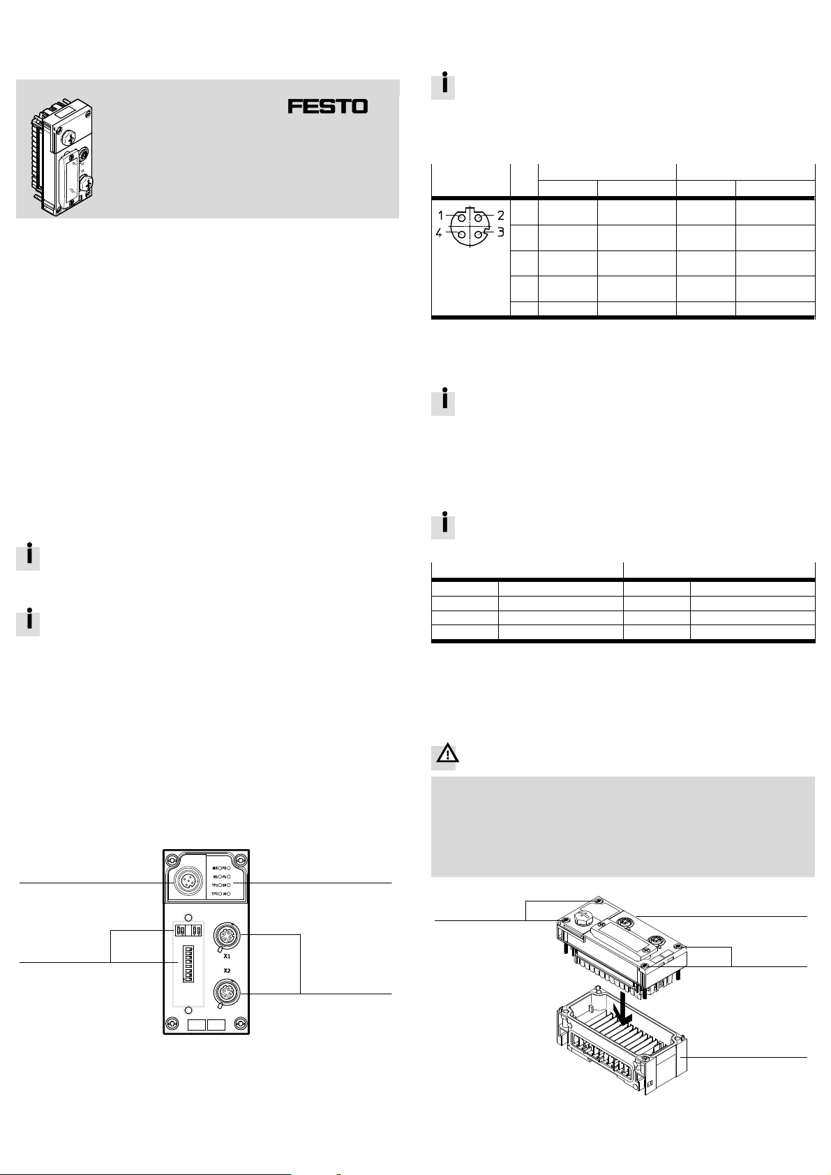
3 Connection and display components
1
2
3
4
1LED indicators
2Network connections [X1], [X2]1)
3DIL switches
4Service interface2)
1) 2× socket, M12, D-coded, 4-pin
2) Socket, M12, A-coded, 5-pin; for the operator unit CPX-MMI or Festo Maintenance Tool CPX-FMT
Fig. 1
3.1 Network connections
There are two 4-pin, D-coded M12 sockets on the bus node for the network con
nection. The sockets are compatible with SPEEDCON plugs. Both connections have
Auto-Negotiation and Crossover Detection (factory setting).
When crossover detection is activated, the bus node automatically
exchanges the transmitted and received data.
If Crossover detection is deactivated, assignment of the pins for transmit
ted and received data at the XP2 connection is crossed. As a result, several
bus nodes in a row can each be connected with a patch cable.
Connection1) Pin X12) X22)
Signal Explanation Signal Explanation
1 TD+ Transmitted
data +
RD+ Received data +
2 RD+ Received data + TD+ Transmitted
data +
3 TD– Transmitted
data –
RD– Received data –
4 RD– Received data – TD– Transmitted
data –
3) Shield Functional earth Shield Functional earth
1) Socket, M12, D-coded, 4-pin
2) Pin activation with deactivated crossover detection
3) Housing; equipotential bonding èCPX system description P.BE-CPX-SYS-…
Fig. 2
If the QuickConnect function has been activated, the crossover detection
function is not available.
3.2 LED indicators – normal operating status
Behaviour of the LED indicators in normal operating status:
– The green LEDs [PS], [PL], [MS] and [NS] are illuminated.
– The green LEDs [TP1] and/or [TP2] light up or flash.
– The red LED [SF] is off.
The yellow LED [M] lights up only when “System start with saved paramet
erisation and CPX extension” is set.
Network-specific LED indicators1) CPX-specific LED indicators2)
MS (red, green) Module status PS (green) Power system
NS (red, green) Network status PL (green) Power load
TP1 (green) “Link/traffic” X1 SF (red) System Failure3)
TP2 (green) “Link/traffic” X2 M (yellow) Modify4)
1) Detailed information (èDescription on the module CPX-FB36-…)
2) Detailed information (èCPX system description P.BE-CPX-SYS-…)
3) Flashes in case of error, error diagnostics (èCPX system description P.BE-CPX-SYS-…)
4) Parameterisation revised or “Force” active.
Fig. 3
4 Mounting and removal
Warning
Uncontrolled movements of the actuators and loose tubing, undefined switching
states of the electronic components
Injury caused by moving parts, damage to machine and to system
Before mounting and installation work:
Switch off the power supply.
Switch off the compressed air supply.
Exhaust any pneumatic components.
2
1
3
2
1Bus node CPX-FB36
2Screw
3Interlinking block
Fig. 4

4.1 Installation
Note
Material damage due to incorrect mounting
Select screws that are suitable for the material of the interlinking block:
– plastic: thread-cutting tapping screws
– Metal: Screws with metric thread.
When ordering a single module, all required screws are supplied.
1. Check seal and sealing surfaces. Replace damaged parts.
2. Push the module carefully and without tilting into the interlinking block up to the
stop.
3. Turn the screws into the existing thread.
4. Tighten the screws in diagonally opposite sequence. Tightening
torque:1 Nm ± 10 %.
4.2 Dismantling
1. Unscrew screws.
2. Pull the module without tilting out of the interlinking block.
5 Power supply
The operating and load voltage supply is fed in via interlinking blocks or end plates
(èCPX system description P.BE-CPX-SYS-…).
Warning
Electric voltage
Injury caused by electric shock, damage to machine and to system
For the electrical power supply, only use PELV circuits in accordance with
IEC 60204-1/EN 60204-1.
Use only voltage sources that ensure a reliable electric separation from the
mains network in accordance with IEC 60204-1/EN 60204-1.
Observe the requirements of IEC 60204-1/EN 60204-1 for PELV circuits.
Always connect all circuits for operating and load voltage supply UEL/SEN, UVAL
and UOUT.
6 DIL switch elements
12
3
1DIL switch 1:
– DIL 1.1: operating mode
– DIL 1.2: network protocol
2DIL switch 2: diagnostic mode and
data field size1)
3DIL switch 3: IP addressing
1) Setting of the data field size is available only in the remote controller operating mode.
Fig. 5
6.1 DIL switch 1 – operating mode and network protocol
Setting DIL switch 1.1 Operating mode
DIL 1.1: OFF
(Factory setting)
Remote I/O
All functions of the CPX terminal are controlled directly by
the higher-order controller. A control block integrated into
the CPX terminal (e.g. CPX-CEC or CPX-FEC) works as a
passive function module without controller.
DIL 1.1: ON Remote controller
A control block integrated into the CPX terminal
(e.g. B. CPX-CEC or CPX-FEC) takes over I/O control. This
operating mode is only useful if a control block is integ
rated into the CPX terminal.
Fig. 6
Setting DIL switch 1.2 Network protocol
DIL 1.2: OFF
(Factory setting)
EtherNet/I P
The CPX terminal uses the EtherNet/IP network protocol.
DIL 1.2: ON Modbus TCP
The CPX terminal uses the Modbus TCP network protocol.
Fig. 7
6.2 DIL switch 2 – diagnostic mode or data field size
The function of DIL switch 2 is dependent on the set operating mode of the
CPX terminal (èFig. 6).
Setting DIL switch 2 Diagnostics mode
(Remote I/O)1)
Data field size
(Remote controller)2)
DIL 2.1: OFF
DIL 2.2: OFF
(Factory setting)
I/O diagnostics interface and
status bits switched off
8 byte I/8 byte O for
communication of the bus
node with a control block
(e. B. CPX-FEC)
DIL 2.1: ON
DIL 2.2: OFF
I/O diagnostics interface is
switched on
32 byte I/32 byte O for
communication of the bus
node with a control block
(e. B. CPX-FEC)3)
DIL 2.1: OFF
DIL 2.2: ON
Status bits switched on 16 byte I/16 byte O for
communication of the bus
node with a control block
(e. B. CPX-FEC)
DIL 2.1: ON
DIL 2.2: ON
Reserved 64 byte I/64 byte O for
communication of the bus
node with a control block
(e. B. CPX-FEC)4)
1) Setting of the diagnostic mode is available only in the remote I/O operating mode.
2) Setting of the data field size is available only in the remote controller operating mode.
3) Revision 12 and above
4) Revision 13 and above
Fig. 8
6.3 DIL switch 3 – IP addressing
Setting DIL switch 3 IP addressing
1234 56 78
3.8:
3.7:
3.6:
3.5:
3.4:
3.3:
3.2:
3.1:
27=
26=
25=
24=
23=
22=
21=
20=
128
64
32
16
8
4
2
1
The type of addressing or the host ID of the IP address of the
bus node is set via DIL switch elements 3.1 ... 3.8.
Possible settings:
0 = Dynamic addressing via DHCP/BOOTP
1 … 254 = Permissible address range
255 = Reset all IP parameters to factory setting
Factory setting: 0
Example:
21+ 22+ 25= 2 + 4 + 32 = 38 (host ID)
Set IP address: 192.168.1.038
Fig. 9
7 Ensuring the degree of protection
Note
Short circuit
Malfunction or damage to the electronics
Use connection technology with the required degree of protection e.g. plug
NECU-M-S-D12G4-C2-ET (èwww.festo.com/catalogue).
Use cover caps to seal unused connections, e.g. cover cap ISK-M12
(èwww.festo.com/catalogue).
Mount the DIL switch cover:
Check seal, place cover and push it down, tighten screws. Tightening torque
maximum 0.4 Nm.
Connection Connecting hardware Cover cap
Network connection (M12) Plug NECU-M-S-D12G4-C2-ET ISK-M12
Service interface (M12) Connecting cable KV-M12-M12-…1) ISK-M12
1) Connecting cable for operator unit (CPX-MMI)
Fig. 10
8 Parameterisation
The CPX terminal and the module described here can be parameterised with the
operator unit (CPX-MMI), the Festo Maintenance Tool (CPX-FMT) software or the
higher-level system.

9 Note on module replacement
Caution
For CPX terminals with a continuously illuminated or flashing “Modify” LED (M),
parameterisation is not automatically created by the higher-level system when
the CPX terminal is replaced during servicing.
Before replacement, note required settings and make them again after re
placement.
When replacing a bus node with the setting [System start with saved para
meters], the CPX terminal is not parameterised automatically by the high
er-order controller.
The bus node CPX-FB36 is compatible with the bus node CPX-FB32:
A bus node CPX-FB32 can be replaced in existing applications by a bus
node CPX-FB36 (Revision 13 or higher) without changing the configuration
of the host system.
10 Start-up behaviour of the CPX terminal
If the “Modify” LED (M) lights up or flashes permanently after the system start,
“System start with saved parameterisation and saved CPX expansion” is set or
“Force” is active.
Additional information on parameterisation, module replacement and
start behaviour of the CPX terminal can be found in the module descrip
tion (èCPX-FB36-…).
11 Technical data
Characteristic Specification/value
General technical data èCPX system description
P.BE-CPX-SYS-…
Degree of protection through housing
in accordance with IEC 60529, completely
mounted, plug connector in plugged-in status or
equipped with cover caps.
IP65/IP671)
Protection against electric shock
Protection against direct and indirect contact in
accordance with IEC 60204-1/EN 60204-1
Through the use of PELV circuits
(Protected Extra-Low Voltage)
Operating voltage supply UEL/SEN [V DC] 24 ± 25 %
Intrinsic current consumption at nominal
operating voltage 24 V from operating voltage
supply UEL/SEN
[mA] Typ. 100 (internal electronics)
Separation of network interface from operating
voltage supply UEL/SEN
Galvanic
Load voltage supply UVAL/OUT [V DC] 24 ± 10 %
Mains buffering time [ms] 10
Module code (CPX-specific)
Remote I/O 224
Remote controller 171
Module identifiers (CPX-MMI)
EtherNet/I P
Remote I/O FB36 EtherNet/IP remote IO V2
Remote controller FB36-RC EtherNet/IP Node
Modbus TCP
Remote I/O FB36-MB Modbus TCP remote IO
Remote controller FB36-MB-RC Modbus TCP node
Network-specific characteristics
Connection technology 2× socket, M12, D-coded, 4-pin
Protocol EtherNet/I P or Modbus TCP2)
Transmission technology Switched fast Ethernet
Specification IEEE 802.3u (100Base-TX)
Transmission rate [Mbit/s] 10/100 (full duplex/half duplex)
Minimum cycle time (RPI) [ms] 1
Maximum data field size (input/output size)
Remote I/O [byte] 64 I/64 O
Remote controller [byte] 8 I/8 O, 16 I/16 O, 32 I/32 O or
64 I/64 O3)
Crossover detection Auto-MDI/MDI-X
Cable specification
Cable type Ethernet twisted pair cable,
screened
Transmission class Category Cat 5/Cat 5e
Cable diameter [mm] 6 … 84)
Wire cross section [mm2]0.14 … 0.75; 22 AWG4)5)
Maximum cable length [m] 100
1) Connected products may only satisfy a lower degree of protection.
2) Based on the Ethernet protocol IEEE 802.3
3) Dependent on the setting of the DIL switch 2 and the revision of the bus node
4) When using the plug NECU-M-S-D12G4-C2-ET from Festo
5) Required for maximum connection length between network participants
Fig. 11
12 Specified standards
Version status
IEC 60204-1:2009-02 IEEE 802.3:2014-00
IEC 60529:2001-02
Fig. 12
Other manuals for CPX-FB36
2
Other Festo Multi-Service Platform manuals