4.1 Mounting
Note
Material damage due to incorrect mounting
Select screws that are suitable for the material of the interlinking block:
– Plastic: Thread-cutting tapping screws
– Metal: Screws with metric thread.
When ordering a single module, all required screws are supplied.
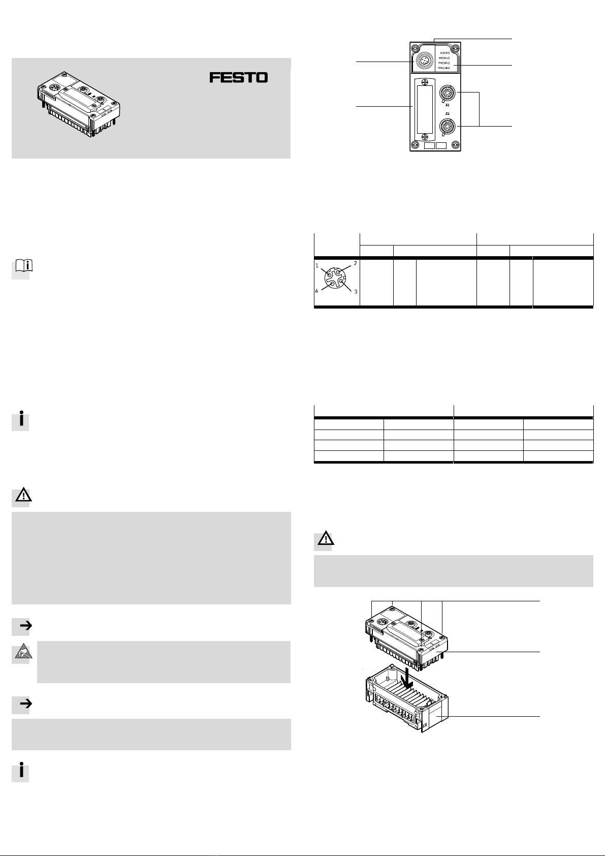
1. Check seal and seal surfaces. Replace damaged parts.
2. Push the module carefully and without tilting into the interlinking block up to the
stop.
3. Turn the screws into the existing thread.
4. Tighten the screws in diagonally opposite sequence. Tightening torque: 0.9 …
1.1 Nm.
4.2 Dismantling
5. Unscrew screws.
6. Pull the module without tilting out of the interlinking block.
5 Power supply
The operating and load voltage supply is fed in via the interlinking block
(èCPX system description P.BE-CPX-SYS-…).
6 DIL switch elements
12
3
1DIL switch 1: Operating mode
2DIL switch 2:1)
– Diagnostics mode (remote I/O)
– I/O mode (remote controller)
3DIL switch 3: Sercos address
1) Dependent on the operating mode (èDIL switch 1)
Fig. 5
6.1 DIL switch 1: (Operating mode)
Setting DIL switch 1 Operating mode
DIL 1.1: OFF
(Factory setting)
Remote I/O
All functions of the CPX terminal are controlled directly by the
Sercos controller or a higher-order controller.
DIL 1.1: ON Remote controller
An FEC or CEC integrated into the CPX terminal controls all
functions of the CPX terminal.
Fig. 6
– The setting of the operating mode via DIL switch 1.1 has priority over all
other settings.
– The switch element 1.2 is reserved and without function.
6.2 DIL switch 2 (diagnostics or I/O mode)
Setting DIL switch 2 Diagnostics mode1) I/O mode2)
DIL 2.1: OFF
DIL 2.2: OFF
(Factory setting)
I/O diagnostics interface
and status bits switched
off
8 byte I/8 byte O for communication
of the bus node with the CPX-FEC
or CPX-CEC.
DIL 2.1: ON
DIL 2.2: OFF
I/O diagnostics interface
is switched on
Reserved
DIL 2.1: OFF
DIL 2.2: ON
Status bits switched on 16 byte I/16 byte O for
communication of the bus node with
the CPX-FEC or CPX-CEC.
DIL 2.1: ON
DIL 2.2: ON
Reserved Reserved
1) Only in the remote I/O operating mode
2) Only in the remote controller operating mode
Fig. 7
The diagnostics mode reduces the available address space.
Take account of this fact when planning the CPX terminal.
– Additional information can be found in the description for the module
(èP.BE-CPX-FB39-…).
6.3 DIL switch 3 (Sercos address)
Setting DIL switch 3 Sercos address
1234 5678
3.8:
3.7:
3.6:
3.5:
3.4:
3.3:
3.2:
3.1:
27=
26=
25=
24=
23=
22=
21=
20=
128
64
32
16
8
4
2
1
Example:
21+ 22+ 25= 2 + 4 + 32 = 38 (Sercos address)
Set Sercos address: 038
Permitted addresses: 1 … 255
Factory setting: 254 (dynamic)
Fig. 8
7 Parameterisation
Note
The CPX terminal and the module described here can be parameterised with the
operator unit (CPX-MMI), the Festo Maintenance Tool (CPX-FMT) software or the
higher-level system.
8 Note on module replacement
Caution
For CPX terminals with a continuously illuminated or flashing Modify LED (M),
parameterisation is not automatically created by the higher-level system when
the CPX terminal is replaced during servicing.
Before replacement, note required settings and make them again after re
placement.
9 Start-up behaviour of the CPX terminal
If the Modify LED (M) lights up or flashes permanently after the system start, “Sys
tem start with saved parameterisation and saved CPX expansion” is set or “Force”
is active.
Additional information on parameterisation, module replacement and
start behaviour of the CPX terminal can be found in the module descrip
tion (èP.BE-CPX-FB39-…).
10 Technical data
Feature Specification/value
General technical data èCPX system description(P.BE-CPX-SYS-…)
Degree of protection through housing1)
in accordance with IEC 60529, completely
mounted, plug connector in plugged-in status
or equipped with cover caps2).
IP65/IP67
Protection against electric shock
Protection against direct and indirect contact
in accordance with IEC 60204-1
through the usage of PELV circuits (protective
extra-low voltage)
Intrinsic current consumption at 24 V
from operating voltage supply for electronics/
sensors (UEL/SEN)
typ. 100 mA (internal electronics)
Separation of network interfaces to UEL/SEN Galvanically separated
Mains buffering time at least 25 ms
Module code (CPX-specific)
Remote I/O 224 (sub-module code 3)
Remote controller 171 (sub-module code 3)
Module identifiers (CPX-MMI, CPX-FMT)
Remote I/O FB39-RIO
Remote controller FB39-RC
Network-specific characteristics
Protocol Sercos III
Specification IEEE 802.3
Transmission rate 100 Mbit/s
Connection length Maximum 100 m
Cable specification
Cable type Industrial Ethernet cable, screened
Transmission class Category Cat 5
Cable diameter 6 … 8 mm
Wire cross section 0.14 … 0.75 mm2, AWG 223)
1) Note that connected devices may only satisfy a lower degree of protection or a smaller temperature
range, etc.
2) Cover caps ISK-M12 included in scope of delivery.
3) Required for maximum connection length between the network participants.
Fig. 9
11 Quoted guidelines and standards
Issue status
IEC 60204-1:2009-02 IEEE 802.3:2012
IEC 60529:2001-02
Fig. 10