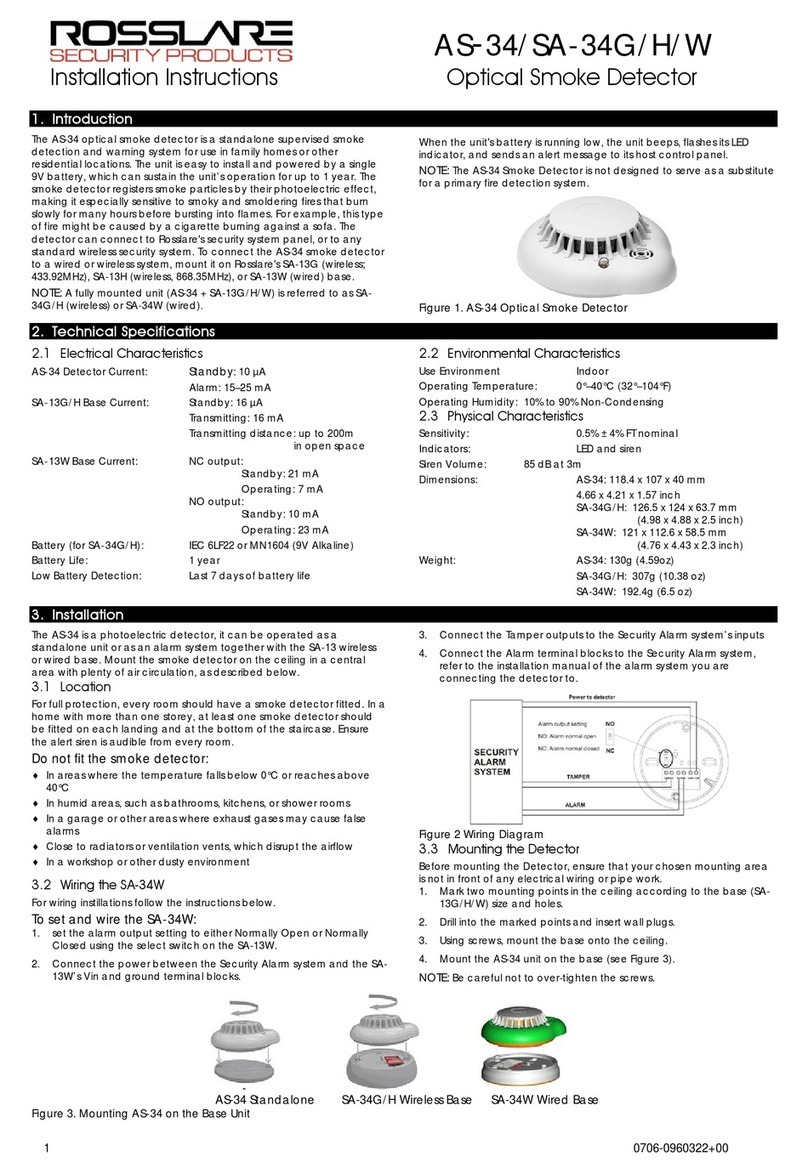
FFE FDL242 User manual

Page 1
FDL242
Linear Smoke Detector
User Guide
EN
Document No: 0044-116-01
www.ffeuk.com

Page 2
Contents
1. Box Contents
2. General Information
3. Wiring Information
4. Mounting
5. Cable Entry
6. Targeting and Alignment
7. Settings
8. Status Indications and Troubleshooting
9. Technical Information
10. Open Source Notice
p.3
p.4
p.5
p.7
p.8
p.9
p.21
p.22
p.24
p.27

Page 3
1. Box Contents
1Base 2Detector Head 3 Reflector 4 Short Range Mask
Example of Product Label:
Depending on the product and approvals, the product
label may differ in terms of information and layout.
Product Version (FS)
Product Order Number
5Cable Ferrite x 2

Page 4
2. General Information
Installation
≥ 0.3 m/12”
0.5 m/
20 m - 50 m/66-164 ft= 1 Reflector
5 m - 20 m/16-66 ft =
1Reflector + Short Range Mask
50 m - 120 m/164-394 ft= 4 Reflectors
5 m - 120 m/
16-394 ft
All installations should comply with local regulations.
Position Beam as high as possible, but with a minimum distance of 0.3 m/12” from Detector and Reflector to ceiling.
Ensure there are no reflective surfaces within 0.5 m of the beam path centre.
Ensure the correct Reflector is selected for the appropriate distance.
Mount Detector and Reflector directly opposite each other.
Do not mount Reflector onto reflective surfaces.
Do not mount Detector or Reflector in areas of direct sunlight.
Do NOT position the Detector where personnel or objects can enter the Beam path.
Do NOT install the Detector or Reflector in environments where condensation or icing are likely to occur unless preventative measures have
been taken.
20”
Safety
Intended Use
The FDL242 Linear Smoke Detector is only permitted for use on an addressed FDnet/C-NET detector line.

Page 5
The FDL242 contains software that processes the output of the detector and generates a Fire and Fault status. This status is transmitted to the
Siemens Fire Control Panel (FCP) over FDnet/C-NET which also powers the FDL242. To wire a detector to a FCP, use the following wiring
diagram. NOTICE: Install one cable ferrite 4 on each cable entry to the detector.
3. Wiring Information
Use of Unshielded Cables
The connection is established from base to base using twisted or non-twisted wire pairs.
Control Panel
1Detector
2Auxiliary Terminals DBZ1190-xx
3Cable Ferrite
4

Page 6
Use of Shielded Cables
The detector line shielding must be connected through in the detector base with auxiliary terminals DBZ1190-xx.
Control Panel
1Detector
2Auxiliary Terminals DBZ1190-xx
3Cable Ferrite
4

Page 7
4. Mounting
Mount the base on solid surface such as a structural wall or girder.
Mark and drill holes for mounting of base. Using appropriate hardware (not supplied) mount base securely in orientation shown.
To preserve the specified IP rating, fit M6 x 30mm x 1.5mm neoprene washers (one per fixing) between the product and the mounting surface.
Plug the cable from the detector head into the
connector on the PCB in the base.
Locate the Detector head on the base. Grip sides
of Detector head and rotate clockwise to lock
together. Ensure the ‘Pip and Dip’ details align.

Page 8
Cable glands should be used on the cable entry of the FDL242 to maintain the IP rating of the enclosure and provide cable strain relief.
Use cable glands with an IP rating of IP55, or greater, which are suitable for the outside diameter of cable(s) being used for the installation.
Two types of cable gland are recommended:
1) M20 x1.5 Metal cable gland, order number A5Q00004478 (Siemens)
2) M20 x1.5 polyamide cable gland and suitable nut, for example:
a) Wire clamping range 4 - 10 mm: article number 53111520 and article number 53119023 (U.I. Lapp GmbH)
b) Wire clamping range 6 - 13 mm: article number 53111420 and article number 53119023 (U.I. Lapp GmbH)
5. Cable Entry
To open cable entries use a twist drill with suitable
diameter and centring point.
Forcefully breaking out the cable entry may
damage the FDL242.
Install one cable ferrite on each
cable entry to the detector.

Page 9
6. Targeting and Alignment
The overall alignment process consists of Targeting (coarse adjustment of FDL242 onto the reflector), Alignment (fine adjustment to the centre of
the reflector) and the activation of a test alarm for functional verification.
The preferred method of Targeting is Laser Targeting: a red laser beam allows the most efficient coarse adjustment of the FDL242 onto an already
mounted reflector. For a mounted FDL242, laser targeting also provides an easy way of locating a suitable mounting position for the reflector. For
details see section ‘Laser Targeting’.
The alternative Targeting process, Prism Targeting, should only be applied if Laser Targeting is not possible, for instance in high ambient light
conditions where the laser might not be visible. For details see chapter ‘Prism Targeting’.
The preferred and most efficient Alignment process is Automatic Alignment. For details see chapter ‘Automatic Alignment’. Only if the Automatic
Alignment fails should the alternative Manual Alignment process be used. For details see section ‘Manual Alignment’.
For the targeting and alignment process the User Interface needs to be accessed by unscrewing the fixing bolt and opening the door as indicated
in the image below. The door should remain attached to the FDL242, however on the rare occasion that it becomes unattached, it is possible to
reattach the tether by reinserting the barbed end.
Introduction
Alignment
and settings
Laser window
Detector Status
indicator

Page 10
Alignment Status indicators Slide Switch
Settings Switch
Direction keys
Targeting-Laser/Prism
Alignment-Auto/Manual
Align Operate
The lower four switches of the Settings Switch have no function

Page 11
Alignment Status Indicators: see process flow descriptions for Targeting and Alignment on the following pages.
Switch settings for different processes:
- Laser Targeting:
- Settings: “Alignment-Auto” or “Alignment-Manual”, “Targeting-Laser”
- Start Laser Targeting by changing Slide Switch from “Operate” to “Align”
- Automatic Alignment after Targeting:
- Settings: “Alignment-Auto”, “Targeting-Laser” or “Targeting-Prism”
- Start Automatic Alignment by changing Slide Switch from “Align” to “Operate”
- Prism Targeting:
- Settings: “Alignment-Auto” or “Alignment-Manual”, “Targeting-Prism”
- Start Prism Targeting by changing Slide Switch from “Operate” to “Align”
- Manual Alignment after Targeting:
- Settings: “Alignment-Manual”, “Targeting-Laser” or “Targeting-Prism”
- Start Manual Alignment by changing Slide Switch from “Align” to “Operate”
- Normal operation:
- Settings: Alignment: Auto or Manual, Targeting: Laser or Prism
- Normal operation is automatically started after successful finalization of Alignment process
Direction Keys: used to align the FDL242 in the laser targeting, prism targeting and manual alignment processes.
User Interface

Page 12
General Remarks
To enable the Targeting and Alignment process the FDL242 needs to be powered. The following options are available:
- Siemens Fire Control Panel
- Line Tester FDUL221
- 24 V DC power supply or battery
When using a Siemens Fire Control Panel with the FDL242 commissioned on the fieldbus the detector must be set into Device Test Mode at the
Siemens Fire Control Panel.
The targeting and alignment process will only work for supply voltages above 20 V. For normal operation the right-hand green LED flashes once
per second for targeting, and twice every 3 seconds for alignment. If the flashes are slower – once every 3 seconds for targeting and twice every
6 seconds for alignment – this indicates that the supply voltage is too low. In this case targeting or alignment will not work properly and the cause
of the low supply voltage needs to be found and removed.

Page 13
This chapter describes the process for a new FDL242 which is to be run through the Targeting and Alignment process for the very first time. If a
previously operated and aligned FDL242 is to be used in a new mounting situation the required process deviations are described in the chapter
‘Realignment of FDL242’.
Before powering the FDL242 the switches need to be in the following positions (default): “Alignment-Auto”, “Targeting-Laser”, Slide Switch:
“Operate”
1. To start Laser Targeting move the slide switch (2) to “Align”.
Laser Targeting and Automatic Alignment of a New FDL242
DANGER
Laser radiation class 3R 5 mW, Wavelength 630…680 nm
Severe eye injury
• Avoid direct eye exposure to laser beam.
• Follow local regulations for use of products with Class 3R lasers
1
2
2. The right-hand green LED flashes once per second to indicate the system is in targeting mode.
WARNING: The laser can become activated at any time as long as switch 2 is in
the left position (Align).

Page 14
3. If a reflector is already mounted use the direction keys to move the laser point towards the centre of the reflector.
If the reflector is not yet mounted you can also use the direction keys to move the laser point towards the intended reflector mounting position.
After mounting the reflector make sure that the laser point appears approximately in the centre of the reflector. If the laser cannot be seen, for
example in very bright environments or over long distances, then the Prism Targeting mode can be used: see chapter ‘Prism Targeting’.
1
2
4. To begin the Automatic Alignment move the slide switch to ‘Operate’

Page 15
Right-hand green LED flashes twice every 3 seconds to indicate the system is in
alignment mode.
Left-hand green LED indicates at which stage (1…5) the process is.
The amber LED in the middle indicates a failure. The number of times it flashes
indicates which stage failed.
a
a
a
The alignment status LEDs flash to show progress:
NOTICE: The maximum duration of the
Automatic Alignment process is 5 minutes. If the
power supply to the FDL242 is to be removed
after alignment, make sure that the Automatic
Alignment has successfully completed before
power is removed, otherwise the detector will
be in fault state at next start-up and the Automatic
Alignment will need to be repeated.
If alignment fails, ensure that the correct number of reflectors are installed, that the correct clearance has been given, and that there are no
reflective surfaces around the reflector or close to the beam path, and try the alignment again.
If alignment repeatedly fails, it is possible to do a manual alignment. See Manual Alignment. Once the alignment is successfully completed, the
right-hand green LED flashes for 10 seconds.
The FDL242 is now ready for selection of Alarm Thresholds.
The Detector can be tested to ensure it is operating and connected to the Siemens Fire Control Panel correctly. To activate the test
alarm, see chapter 8 Status Indications and Troubleshooting, ‘Activating the test alarm’.

Page 16
Prism targeting should only be used when the laser cannot be seen, for instance in high ambient lighting conditions or over very long distances.
Prism Targeting
2. To begin targeting, move the Slide Switch (2) to the left-hand position.
1. On the Settings Switch set the Targeting switch (1) to the right-hand position.
a
The Alignment Status indicator LEDs (left-hand, middle) will flash together for up to 3 seconds to show
the detector has started Prism targeting.
Prism targeting in progress: Right-hand green LED flashes once per second to indicate the system is in targeting mode.
If the left-hand green LED stays illuminated the detector is receiving enough light back from the reflector.
a
1
2
DANGER
Laser radiation class 3R 5 mW, Wavelength 630…680 nm
Severe eye injury
• Avoid direct eye exposure to laser beam.
• Follow local regulations for use of products with Class 3R lasers
WARNING: The laser can become activated at any time as long as switch 2 is in
the left position (Align).

Page 17
3. Cover the reflector.
4.1 If the left-hand green LED goes off then the light being received by the detector is coming from the reflector and you can now proceed to
the alignment stage. See page 13 for Automatic Alignment or page 17 for Manual Alignment.
4.2 If the left-hand green LED stays illuminated with the reflector covered then the light received by the detector is being reflected by some
other object in or around the beam path.
Take care to make sure there are no reflective objects within 0.5 m of the centre of the beam path, and try Prism Targeting again.
4.3 If the amber LED flashes every second then the detector is not receiving enough light from the reflector. The number of flashes indicate
how strong a signal it is receiving. Using the direction buttons, move the detector in one axis until the amber flashes increase. If the
number of flashes stays the same, then keep going in the same direction. If the number decreases, then reverse direction. Once the
number of flashes starts to increase then keep going until either:
• The left-hand green LED comes on, at which point cover the reflector as described under point 3 above.
• The amber LED flashes start to decrease again, at which point reverse direction for 2 steps and perform the same process in the other
axis.
If Prism Targeting has been performed on both axes and the left-hand green LED is still not on, then ensure the following:
• Correct number of reflectors for the range has been used
• The distance has not exceeded the maximum (120 m)
• The reflector and detector are parallel to each other
After the above points are assured, try the Prism Targeting again.
• Avoid direct eye exposure to laser beam.
• Follow local regulations for use of products with Class 3R lasers

Page 18
The green and amber LEDs may flash if the detector needs to perform an initial power adjustment.
Once they have stopped flashing, move on to step (3).
2. Move the Slide Switch (2) to the right-hand position (“Operate”). The right-hand green LED flashes twice every 3 seconds to indicate
the system is in alignment mode.
Manual Alignment
Manual alignment should only be used when Automatic alignment has failed even after it has been verified that the correct number of reflectors
have been installed and the correct clearance around the beam path has been given.
Perform targeting as previously described, and then do the following:
1. On the Settings Switch set the Alignment switch (1) to the right-hand position (“Manual”).
a
3. Use the direction buttons to move the detector in the up-down axis. Press the down button once, and wait to see what the LED indication
shows.
If both amber and green LEDs flash, the signal has not changed so no further movement in that axis is needed.
a
If the amber LED flashes, the signal is smaller and the detector is moved away from the reflector.
Using the direction buttons, reverse direction for 2 steps. This time there should be a green flash.
a
1
2

Page 19
If the left-hand green LED flashes, the signal is larger and the detector is moving closer to the reflector.
The next movement must be in the same direction. Keep moving the detector, waiting for the LED flash each time.
If the left-hand green LED keeps flashing, keep going in the same direction.
If the amber and the green LED flashes, then move onto the other axis (see step (4) below).
If the amber LED flashes, move back in the opposite direction once, then move onto the other axis (see step (4) below).
a
6. Follow the same process as in step (3), this time in the left-right axis. Start by moving in the left direction.
a
7. Once the alignment has been completed on both axes move the Alignment switch (1) to the left-hand position (“Auto”).
The right-hand green LED will flash for 10s.
The Detector can be tested to ensure it is operating and connected to the Siemens Fire Control Panel correctly.
To activate the test alarm, see chapter 8 Status Indications and Troubleshooting, ‘Activating the test alarm’.
4.
4.
5.

Page 20
Realignment of a previously aligned FDL242
If a previously aligned FDL242 is to be reused in a new mounting situation it must be realigned. If the FDL242 is started up in the new mount-
ing situation for the first time it will apply the previous alignment data and the FDL242 will most likely generate an alarm immediately after
startup.
When the realignment process is to be done by means of a Line Tester FDUL221 or a 24 V DC power supply the alarm will not have any
impact and the Targeting and Alignment process described above can be applied without changes.
However, when the realignment is to be done by means of a Siemens Fire Control Panel an alarm generated by the FDL242 inhibits the
activation of the Device Test Mode. In order to enable realignment with a Siemens Fire Control Panel the Slide Switch needs to be set to Align
before the startup of the fieldbus line.
DANGER
Laser radiation class 3R 5 mW, Wavelength 630…680 nm
Severe eye injury
• Avoid direct eye exposure to laser beam.
• Follow local regulations for use of products with Class 3R lasers
WARNING: The laser can become activated at any time as long as switch 2 is in
the left position (Align).
If the FDL242 is powered up with the Slide Switch on “Align” it will directly enter Targeting mode. The FDL242 will then block the alarm and
issue a fault message instead. The Targeting and Alignment process steps described above can then be executed. After successful completion of
the Targeting and Alignment process the fault message will be retracted and the FDL242 will enter normal operation.
1
2
Table of contents
Other FFE Smoke Alarm manuals
Popular Smoke Alarm manuals by other brands
Xtralis
Xtralis ICAM IAS-2 Product guide

Universal Electronics
Universal Electronics CD-9775 instructions

BRK electronic
BRK electronic Smoke Alarm user manual

Gentex
Gentex 7109CS installation instructions
SmartCell
SmartCell SC-23-0220-0001-99 installation guide
24/7 FIRE PROTECTION
24/7 FIRE PROTECTION FP946 manual


