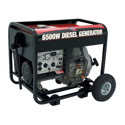
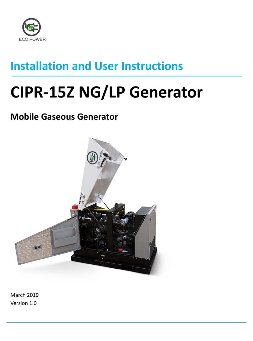
FG Wilson OLYMPIAN 1001 Series User manual

GENERATING SET
OPERATOR’S MANUAL

i

GENERATING SET
OPERATOR’S MANUAL
This manual has been designed as a guide to operators to aid in starting, stopping and otherwise operating the generating
set. The Generating Set Technical Operation and Maintenance Manual, the Engine Manual and the Alternator Manuals are
designed for qualified generating set technicians for installation, maintenance and trouble shooting of the set.
Document: PWPO1 - GB
Issue Date: 02/09
Part Number: 277-584
ii

TABLE OF CONTENTS
1. INTRODUCTION.......................................................................................................................................................................................................1
2. SAFETY.....................................................................................................................................................................................................................1
2.1 General...............................................................................................................................................................................................................1
2.2 Installation, Handling and Towing.......................................................................................................................................................................1
2.3 Fire and Explosion..............................................................................................................................................................................................1
2.4 Mechanical..........................................................................................................................................................................................................1
2.5 Chemical.............................................................................................................................................................................................................1
2.6 Noise...................................................................................................................................................................................................................1
2.7 Electrical.............................................................................................................................................................................................................1
2.8 First Aid For Electric Shock ................................................................................................................................................................................2
3. GENERAL DESCRIPTION........................................................................................................................................................................................3
4. CONTROL SYSTEM DESCRIPTION AND TROUBLE SHOOTING ........................................................................................................................4
4.1 Control System Description and Identification....................................................................................................................................................4
4.2 Functional Description 1001 Series Control System ..........................................................................................................................................6
4.3 Functional Description 2001, 4001 and 4001E Series Control Systems............................................................................................................6
4.4 Functional Description PowerWizard Control Systems .....................................................................................................................................8
4.5 Control System Options and Upgrades..............................................................................................................................................................8
4.6 Control System Fault Finding/Trouble Shooting Guide 1001, 2001, 4001, 4001E...........................................................................................11
4.7 Control System Fault Finding/Trouble Shooting Guide PowerWizard Panels..................................................................................................13
4.8 Load Transfer Panels...........................................................................................................................................................................................19
4.9 Engine Interface Module Description................................................................................................................................................................19
4.10 Output Circuit Breaker Description.................................................................................................................................................................19
5. OPERATION ...........................................................................................................................................................................................................20
5.1 General.............................................................................................................................................................................................................20
5.2 Pre-Start Checks (applicable to all control systems)........................................................................................................................................20
5.3 Normal Startup/Shutdown - Key Start Panel (1001 Series)..............................................................................................................................20
5.4 Normal Manual Startup/Shutdown - Autostart Panel (2001, 4001 or 4001E Series)........................................................................................21
5.5 Automatic Startup/Shutdown - Autostart Panel (2001, 4001 or 4001E Series)................................................................................................21
5.6 Normal Manual Startup/Shutdown - PowerWizard Autostart Panels................................................................................................................22
5.7 Automatic Startup/Shutdown - PowerWizard Autostart Panels........................................................................................................................22
6. MAINTENANCE ......................................................................................................................................................................................................23
6.1 Battery Removal and Fitting..............................................................................................................................................................................23
HAZARD LABEL LEGEND..............................................................................................................................................................................................24
INDEX ..............................................................................................................................................................................................................................25
iii

1. INTRODUCTION
This generating set is one of a family of heavy duty industrial
generating sets designed to be ready to run when it arrives,
requiring only the addition of coolant, fuel and battery acid.
Years of diesel generating set experience has gone into the
set to produce a quality source of electrical power that is
efficient and reliable.
This Operator’s Manual has been prepared to assist in
operation of the generating set.
Always ensure that maintenance, adjustments and repairs are
done by personnel who are authorised to do the work and
have been properly trained.
Every generating set is uniquely defined by a model number
and serial number indicated on a rating plate generally affixed
to the alternator housing. This information is required when
ordering spare parts or when service or warranty work is
required.
2. SAFETY
2.1 General
The generating set is designed to be safe when used in
the correct manner. Responsibility for safety, however,
rests with the personnel who use the set. The following
safety precautions, if followed, will minimise the possibility
of accidents. Before performing any procedure or
operating technique, it is up to the user to ensure that it is
safe. The generating set should only be operated by
personnel who are authorised and trained.
WARNING:
!Read and understand all safety precautions and
warnings before operating the generating set.
!Failure to follow the instructions, procedures, and
safety precautions in this manual may increase the
possibility of accidents and injuries.
!Never start the generating set unless it is safe to do
so.
!Do not attempt to operate the generating set with a
known unsafe condition.
!If the generating set is unsafe, fit danger notices and
disconnect the battery negative ( - ) lead so that it
cannot be started until the condition is corrected.
!Disconnect the battery negative ( - ) lead prior to
attempting any repairs or cleaning inside the
enclosure, if equipped.
!Install and operate this generating set only in full
compliance with relevant National, Local, or Federal
Codes, Standards or other requirements.
2.2 Installation, Handling and Towing
A qualified generating set technician should refer to the
Technical Manual for this information.
2.3 Fire and Explosion
Fuels and fumes associated with generating sets can be
flammable and potentially explosive. Proper care in
handling these materials can dramatically limit the risk of
fire or explosion. However, safety dictates that fully
charged BC and ABC fire extinguishers are kept on hand.
Personnel must know how to operate them
WARNING:
!Ensure the generating set room is properly
ventilated.
!Keep the room, the floor and the generating set
clean. When spills of fuel, oil, battery electrolyte or
coolant occur, they should be cleaned up
immediately.
!Never store flammable liquids near the engine.
!Store oily rags in covered metal containers.
!Do not smoke or allow sparks, flames or other
sources of ignition around fuel or batteries. Fuel
vapours are
explosive. Hydrogen gas generated by charging batteries
is also explosive.
!Avoid refilling the fuel tank while the engine is
running.
!Do not attempt to operate the generating set with
any known leaks in the fuel system.
2.4 Mechanical
The generating set is designed with guards for protection
from moving parts. Care must still be taken to protect
personnel and equipment from other mechanical hazards
when working around the generating set.
WARNING:
!Do not attempt to operate the generating set with
safety guards removed. While the generating set is
running do not attempt to reach under or around the
guards for any reason.
!Keep hands, arms, long hair, loose clothing and
jewellery away from pulleys, belts and other moving
parts.
Attention: Some moving parts can not be seen
clearly when the set is running.
!Keep access doors on enclosures, if equipped,
closed and locked when not required to be open.
!Avoid contact with hot oil, hot coolant, hot exhaust
gases, hot surfaces and sharp edges and corners.
!Wear protective clothing including gloves and hat
when working around the generating set.
2.5 Chemical
Fuels, oils, coolants, lubricants and battery electrolyte
used in this generating set are typical of the industry.
However, they can be hazardous to personnel if not
treated properly.
WARNING:
!Do not swallow or have skin contact with fuel, oil,
coolant, lubricants or battery electrolyte. If
swallowed, seek medical treatment immediately. Do
not induce vomiting if fuel is swallowed. For skin
contact, wash with soap and water.
!Do not wear clothing that has been contaminated by
fuel or lube oil.
2.6 Noise
Generating sets that are not equipped with sound
attenuating enclosures can produce noise levels in excess
of 105 dBA. Prolonged exposure to noise levels above 85
dBA is hazardous to hearing.
WARNING:
!Ear protection must be worn when operating or
working around an operating generating set.
2.7 Electrical
Safe and efficient operation of electrical equipment can be
achieved only if the equipment is correctly operated and
maintained.
WARNING:
!Ensure the generating set, including a mobile set, is
effectively grounded/earthed prior to operation.
!Do not touch electrically energised parts of the
generating set and/or interconnecting cables or
conductors with any part of the body or with any non
insulated conductive object.
!Use only Class BC or Class ABC extinguishers on
electrical fires.
1

2.8 First Aid For Electric Shock
WARNING:
!Do not touch the victim's skin with bare hands until
the source of electricity has been turned off.
Switch off the power, if possible.
Otherwise pull the plug or pull the cable away from
the victim.
If this is not possible, stand on dry insulating material
and pull the victim clear of the conductor, preferably
using insulated material such as dry wood.
If victim is breathing, turn the victim into the recovery
position described below.
If victim is unconscious, perform resuscitation as
required:
OPEN THE AIRWAY:
1. Tilt the victim's head back and lift
the chin upwards.
2. Remove objects from the mouth
or throat (including false teeth,
tobacco, or chewing gum).
BREATHING:
1. Check that the victim is breathing by looking, listening
and feeling for the breath.
CIRCULATION:
1. Check for pulse in the victim's
neck.
IF NO BREATHING BUT PULSE IS
PRESENT:
1. Pinch the victim's nose firmly.
2. Take a deep breath and seal your
lips around the victim’s lips.
3. Blow slowly into the mouth
watching for
the chest to rise. Let the chest fall
completely. Give breaths
at a rate of 10 per minute.
4. If the victim must be left to
get help, give 10 breaths first
and then return quickly and continue.
5. Check for pulse after every 10 breaths.
6. When breathing restarts, place the victim into the
recovery position described later in this section.
IF NO BREATHING AND NO PULSE:
1. Call or telephone for medical help.
2. Give two breaths and start chest
compression as follows:
3. Place heel of hand 2 fingers
breadth above ribcage/breastbone
junction.
4. Place other hand on top and
interlock fingers.
5. Keeping arms straight, press down
4-5 cm (1.5-2 inch) 15 times at a
rate of 80 per minute.
6. Repeat cycle (2 breaths, 15
compressions) until medical help
takes over.
7. If condition improves, confirm pulse
and continue with breaths. Check
for pulse after every 10 breaths.
8. When breathing restarts, place the
victim into the recovery position.
RECOVERY POSITION:
1. Turn the victim onto the side.
2. Keep the head tilted with the jaw
forward to maintain the open
airway.
3. Make sure the victim cannot roll
forwards or backwards.
4. Check for breathing and pulse
regularly. If either stops,
proceed as above.
WARNING:
!Do not give liquids until victim is conscious.
2

3. GENERAL DESCRIPTION
This generating set has been designed as a complete package
to provide superior performance and reliability.
Each generating set is provided with a Rating Label generally
affixed to the alternator housing. This label contains the
information needed to identify the generating set and its
operating characteristics. This information includes, but is not
limited to, the model number, serial number, output
characteristics such as voltage, phase and frequency, output
rating in kVA and kW, and rating type (basis of the rating). For
reference, this information is repeated on the Technical Data
Sheet provided with the Technical Manual. The model and
serial numbers uniquely identify the generating set.
The diesel engine powering the generating set has been
chosen for its reliability and the fact that it has been specifically
designed for powering generating sets. The engine is of the
heavy duty industrial type with 4 stroke or 2 stroke
compression ignition and is fitted with all accessories to
provide a reliable power supply.
The engine electrical system is either 12 or 24 volts DC
depending on the size of the set.
The engine cooling system is comprised of a radiator, a high
capacity pusher fan and a thermostat. The alternator has its
own internal fan to cool the alternator components.
The output electrical power is produced by an alternator fine
tuned to the output of this generating set.
The engine and alternator are coupled together and mounted
on a heavy duty steel baseframe. Except for the largest sets,
this baseframe includes a fuel tank with a capacity of
approximately 8 hours operation at full load. An extended
capacity fuel tank of approximately 24 hours operation may be
fitted instead.
The generating set is fitted with vibration isolators which are
designed to reduce engine vibration being transmitted to the
foundation on which the generating set is mounted. These
isolators are fitted between the engine/alternator feet and the
baseframe. Alternately, on larger models the engine/alternator
is rigidly mounted on the baseframe and the vibration isolators
are supplied loose to be fitted between the baseframe and the
foundation.
An exhaust silencer is provided loose for installation with the
generating sets. The silencer and exhaust system reduce the
noise emission from the engine and can direct exhaust gases
to safe outlets.
One of several types of control systems and panels may be
fitted to control the operation and output of the set and to
protect the set from possible malfunctions. Section 4 of this
manual provides detailed information on these systems and
will aid in identification of the control system fitted on the
generating set.
To protect the alternator, a suitably rated circuit breaker
selected for the generating set model and output rating is
supplied mounted in a steel enclosure.
3

4. CONTROL SYSTEM DESCRIPTION AND TROUBLE
SHOOTING
4.1 Control System Description and Identification
4.1.1 Description: An advanced electronic control system
has been designed and installed to control and monitor the
generating set. Depending on the requirements of the set,
one of several different standard control systems may be
fitted. These include the 1001 Series Keystart System,
2001 Series Autostart System, 4001 Series Deluxe
Autostart System 4001E Series Enhanced Deluxe
Autostart System and the PowerWizard Autostart Systems.
Other more specialised systems may be installed for
specific installations in which case separate
documentation is provided.
These control systems consist of three major components
working together - a control panel, an engine interface
module (EIM), and an alternator output circuit breaker.
The control panel provides a means of starting and
stopping the generating set, monitoring its operation and
output, and automatically shutting down the set in the
event of a critical condition arising such as low oil pressure
or high engine coolant temperature. A 1001, 2001, 4001,
4001E or PowerWizard Series Panel is installed as
appropriate for the requirements of the generating set
installation.
The Engine Interface Module is a sealed, engine mounted
module that provides switching relays for the Starter Motor
Solenoid, Glow Plug and Fuel Solenoid. Each of these
circuits is protected with individual fuses mounted in the
module. Individual LED’s illuminate when each circuit is
energised. The Engine Interface Module is available in four
models depending on the type of control panel being used
- the 12 volt EIM SR, the 12 volt EIM Plus, 24 volt EIM SR
and the 24 volt EIM Plus. The table below indicates which
EIM module is used on which generating sets:
Panel Sets up to 150kVA Sets above 150kVA
Fitted (12 volt systems) (24 volt systems)
1001 12 Volt EIM SR 24 Volt EIM Plus
2001 12 Volt EIM Plus 24 Volt EIM Plus
4001 12 Volt EIM Plus 24 Volt EIM Plus
4001E 12 Volt EIM Plus 24 Volt EIM Plus
PowerWizard 12 Volt EIM SR 24 Volt EIM SR
The power output circuit breaker serves to protect the
alternator by automatically disconnecting the load in the
event of overload or short circuit. It also provides a means
of switching the generating set output.
4.1.2 Panel Equipment (1001, 2001, 4001, 4001E):
Before starting or running the generating set, the operator
should become fully acquainted with the instruments and
controls. The instruments should be observed from time to
time while the generating set is running so that any
abnormal readings can be detected before problems arise.
Figure 4.1 shows typical diagrams of each of the control
panels. Addition of optional equipment will add items to
the panel so the panel fitted on the generating set may be
slightly different from the typical ones shown. The
following descriptions explain the function of each item on
the panels:
1. AC VOLTMETER - A voltmeter that indicates the AC
voltage generated at the alternator output terminals.
The reading indicated on the voltmeter will vary
depending on the position of the voltmeter selector
switch (item 2). It should not, however, vary while
the set is operating. If the meter gives no reading
while the generating set is running, ensure that the
AC voltmeter selector switch is not in the OFF
position.
2. AC VOLTMETER SELECTOR SWITCH - A selector
switch allowing the operator to select voltage reading
between phases or between a phase and neutral.
The OFF position allows the voltmeter "zero"
position to be checked while the generating set is
running.
3. AC AMMETER - An ammeter that indicates the AC
electrical current being delivered which is dependant
on the connected load. A separate reading from
each of the phases is possible using the ammeter
selection switch (item 4). If the meter gives no
reading while the generating set is running, ensure
that the AC ammeter selector switch is not in the
OFF position.
4. AC AMMETER SELECTOR SWITCH- A selector
switch allowing the operator to select a current
reading from each of the phases. The OFF position
allows the ammeter "zero" position to be checked
while the generating set is running.
5. FREQUENCY METER - A meter that indicates the
output frequency of the generating set. At partial
load the frequency will be slightly higher than
normal, depending on the droop of the governor. In
practice, no load frequencies of approximately 52
and 62 Hz for 50 Hz and 60 Hz respectively, are
considered normal. The frequencies will fall, as the
set is loaded, to 50 Hz and 60 Hz at full load.
6. HOURS RUN METER - A meter that indicates the
total number of hours of generating set operation to
aid in maintenance.
7. ENGINE WATER TEMPERATURE GAUGE - A
temperature gauge connected to a sensor in the
engine to monitor engine coolant temperature. The
normal operating temperature should be
approximately 85°C (185°F).
8. DC BATTERY VOLTMETER - A voltmeter that
indicates the state of charge of the battery. When
the engine is at standstill the normal battery voltage
will be 12 to 14 volts on a 12 volt system and 24 to
28 volts on a 24 volt system. During starting, the
needle will drop to about 70% of normal and oscillate
as the engine cranks. Once the engine has started,
the needle should return to its normal value. If the
battery charging alternator is charging correctly, the
voltage reading will always be higher with the
generating set running than when it is stopped.
9. ENGINE OIL PRESSURE GAUGE - A gauge to
monitor engine oil pressure from the moment the
engine is cranked. The proper oil pressure rating
should be approximately 35 to 60 p.s.i. for 50 Hz and
45 to 65 p.s.i. for 60 Hz. On cold engines the oil
pressure will be significantly higher until the engine
warms up.
10. FAULT INDICATOR LAMPS - Fault lamps that
illuminate to indicate that the protective circuitry has
sensed the indicated condition. The lamp should be
red on conditions for which the system will initiate a
shutdown of the set. For alarms, the lamp can be
red or amber.
11. LAMP TEST PUSHBUTTON - A button to test the
fault lamps and to reset an alarm warning lamp and
circuitry after an alarm has been initiated.
12. KEY SWITCH (1001 Series Only) - A four position
switch that provides a means of starting and
operating the generating set.
Position "O" - Off/Reset
Power is turned off and protection circuitry is reset in
this position.
Position "l" - On
DC power is supplied to the control system and the
fault protection timer relay is initiated.
Position “ ” - Thermostart
DC power is supplied to the thermostart circuit, if
fitted.
Position “ ” - Start
DC power is supplied to the starter motor to crank
the engine. The thermostart circuit is also powered,
if fitted.
4

13. CONTROL SWITCH (2001, 4001 and 4001E Series
Only) - A three position switch that provides a means
of controlling the generating set functions.
Position 1 - “RUN”
The auto start function is initiated to immediately
start and run the generating set.
Position 2 - “STOP”
The genset is shut down if running, and automatic
start is inhibited. The fault protection circuitry is
reset in this position.
Position 3 - “AUTO”
The control circuitry is ready to initiate an automatic
start upon receiving a remote start signal.
14. EMERGENCY STOP PUSHBUTTON (2001, 4001
and 4001E Series Only) - A red lock-down
pushbutton that immediately shuts down the
generating set and will inhibit start until the
pushbutton has been released by turning it
clockwise. Pressing this button also illuminates the
“OVERSPEED” fault lamp even though an
overspeed has not occurred. Prior to restarting the
set, this fault lamp must be reset by turning the
Control Switch to “STOP”, or by turning the key
switch on 1001 Series Control Panels to position "O"
(off).
15. THERMOSTART PREHEAT BUTTON (2001, 4001
and 4001E Series Only) - A button to power the
thermostart preheat circuit, if fitted.
4.1.3 Panel Equipment for PowerWizard: Before starting
or running the generating set, the operator should become
fully acquainted with the control module’s display and push
buttons. The display should be observed from time to time
while the generating set is running so that any abnormal
readings can be detected before problems arise.
Figure 4.1 (c) shows a typical layout of the PowerWizad
control panel. Addition of optional equipment may add
items to the panel so the panel fitted on the generating set
may be slightly different from the typical one shown. The
following descriptions explain the function of each standard
item on the panels:
1. DISPLAY SCREEN - This screen will display all the
generating set’s information from sensor readings to
event logs. Please see section 4.1.4 for display
preferences.
2. AC OVERVIEW - The “AC Overview” key will
navigate the display to first screen of AC information.
The “AC Overview” information contains various AC
parameters that summarize the electrical operation
of the generating set.
3. ENGINE OVERVIEW - The “Engine Overview” key
will navigate the display to the first screen of engine
information. The “Engine Overview” information
contains various engine parameters that summarize
the operation of the generating set.
4. YELLOW WARNING LIGHT - A flashing yellow light
indicates that there are unacknowledged active
warnings. A solid yellow light indicates that there are
acknowledged warnings active. If there are any active
warnings the yellow light will change from flashing
yellow to solid yellow after the Alarm Acknowledge
key is pressed. If there are no longer any active
warnings, the yellow light will turn off after the
“Acknowledge” key is pressed.
5. RED SHUTDOWN LIGHT - A flashing red light
indicates that there are unacknowledged active
shutdown events. A solid red light indicates that there
are acknowledged shutdown events active. If there
are any active shutdown events the red light will
change from flashing red to solid red after the Alarm
Acknowledge key is pressed. Any condition that has
caused a shutdown event must be manually reset. If
there are no longer any active shutdown events, the
red light will turn off.
6. ALARM ACKNOWLEDGMENT SILENCE - Pressing
the “Acknowledge” key will cause the horn relay
output to turn off and silence the horn. Pressing the
key will also cause any yellow or red flashing lights to
turn off or to become solid depending on the active
status of the alarms. The “Acknowledge” key may
also be configured to send out a “Global Alarm
Silence ” on “J1939 Data Link” which will silence
horns on annunciators.
7. LAMP TEST - Pressing and holding the “Lamp Test”
key will cause all of the LED’s and the display screen
pixels to turn on solid until the key is released.
8. RUN - Pressing the “RUN” key will cause the engine
to enter the “RUN” mode.
9. AUTO - Pressing the “AUTO” key will cause the
engine to enter the “AUTO” mode.
10. STOP - Pressing the “STOP” key will cause the
engine to enter the “STOP” mode.
11. UP - The “Up” key is used to navigate up through the
various menus or monitoring screens. The “Up” key is
also used during setpoint entry. During numeric data
entry the Up key is used in order to increment the
digits (0-9). If the setpoint requires selection from a
list, the “Up” key is used to navigate UP through the
list.
12. ESCAPE - The “ESCAPE” key is used during menu
navigation in order to navigate up through the
menu/sub-menu structure. Each key press causes
the user to move backwards/upwards through the
navigation menus. The “Escape” key is also used to
cancel out of data entry screens during setpoint
programming. If the “Escape” key is pressed during
setpoint programming, none of the changes made on
screen will be saved to memory.
13. RIGHT - The “Right” key is used during setpoint
adjustment. During numeric data entry, the “Right”
key is used to choose which digit is being edited. The
“Right”key is alsoused during certainsetpoint
adjustments to select or deselect a check box. If a
box has a check mark inside the box, pressing the
“Right” key will cause the check mark to disappear,
disabling the function. If the box does not have a
check mark inside the box, pressing the “Right” key
will cause a check mark to appear, Enabling the
function.
14. ENTER - The “Enter” key is used during menu
navigation to select menu items in order to navigate
forward/downward in the menu/sub-menu structure.
The “Enter” key is also used during setpoint
programming in order to save setpoints changes.
Pressing the “Enter” key during setpoint programming
causes setpoint changes to be saved to memory.
15. DOWN - The “Down” key is used to navigate down
through the various menus or monitoring screens.
The “Down” key is also used during setpoint entry.
During numeric data entry the “Down” key is used in
order to decrement the digits (0-9). If the setpoint
requires selection from a list, the “Down” key is used
to navigate DOWN through the list.
16. LEFT - The “Left” key is used during setpoint
adjustment. During numeric data entry, the“ Left” key
is used to choose which digit is being edited. The
“Left” key is also used during certain setpoint
adjustments to select or deselect a check box. If a
box has a check mark inside the box, pressing the
“Left” key will cause the check mark to disappear,
disabling the function. If the box does not have a
check mark inside the box, pressing the “Left ” key
will cause a check mark to appear, enabling the
function.
17. EMERGENCY STOP PUSHBUTTON - A red lock-
down pushbutton that immediately shuts down the
generating set and will inhibit start until the
pushbutton has been released by turning it clockwise.
Prior to restarting the set, this fault must be reset by
5

pressing the ‘stop’ button on the module and resetting
the fault in the ‘event log menu’.
18. MODULE DATA LINK CONNECTION - This enables
the service tool to communicate with the module.
4.1.4 Display Preferences for PowerWizard Panels: To
change the display preferences, from the main menu scroll
down to the 'Preferences' item (last in the menu). Press
the 'Enter' Key. Scroll down through the preferences menu
until the desired display preference is highlighted. Press
'Enter' to adjust this preference.
CONTRAST: The display contrast may require adjustment
from the factory default depending on viewing angle and
ambient temperature. The contrast is adjusted between
0% and 100% by pressing the left and right keys. Pressing
Enter accepts the changes and Escape aborts the
changes.
BACKLIGHT: The backlight is usually left at 100%,
however on occasions the user may wish to reduce the
backlight intensity. The backlight can be adjusted between
0 to 100% by pressing the left and right keys. Pressing
Enter accepts the changes and Escape aborts the
changes.
PRESSURE UNITS: The pressure units can be adjusted
between kPa/psi/bar. Use the left and right keys to select
the preferred pressure units. Pressing Enter accepts the
new pressure units; pressing escape aborts the change in
pressure units.
TEMPERATURE UNITS: The temperature units can be
adjusted between ºC and °F. Use the left and right keys to
select the preferred temperature units. Pressing Enter
accepts the change; pressing escape aborts the change.
VOLUME: Volume is used on some optional parameters
(such as fuel consumption rate). It can be selected
between Litres, US Gallons and Imperial Gallons using the
left and right keys. Pressing enter accepts the new volume
units; pressing escape aborts the change to the volume
units.
DISPLAY LANGUAGE: The display language can be
adjusted between the customer language and 'Technician
English'. 'Technician English' is a reduced version of the
display strings in English to facilitate factory testing and
commissioning. As it is not a complete set of display
strings, it is not suitable for customer use.
4.2 Functional Description 1001 Series Control System
The 1001 Series Control System provides for manual
starting and stopping of the generating set and provides
protection for the engine against both high engine coolant
temperature and low oil pressure.
4.2.1 Functions (1001 Series): Section 5 of this manual
provides detailed guidance and checklists for the operation
of the generating set. This section provides a more
detailed description of the functions of the control system
during operation.
W
!The Key Switch must not be turned to position
"
ARNING:
" (Thermo) or " " (Start) while the engine
is running.
During start, turning the Key Switch through Position "l"
(On) to Position " " (Thermo) activates the
thermostart, if fitted. This preheats the induction air and
should be held for 7 seconds. Turning the Key Switch
further to Position " " (Start) cranks the engine. The
starter motor will be disengaged when the Key Switch is
released so it must be held in this position until the engine
starts and then immediately released and allowed to return
to Position "l" (On).
To prevent overheating of the starter motor the engine
should not be cranked for more than 5 to 7 seconds. An
interval of 10 seconds should be allowed between start
attempts. If the engine has not started after 4 attempts,
refer to a qualified generating set technician.
Once the generating set is running properly, the electrical
load is applied to the set by switching the alternator output
circuit breaker to "ON" (handle in the up position).
When shutting down the generating set, the load should be
turned off by switching the alternator output circuit breaker
to "OFF" (handle down). The engine should be allowed to
cool prior to stopping it. After a few minutes the Key
Switch is turned to Position "O" (Off) which shuts the
generating set down.
In case of emergency where immediate shutdown is
necessary, the Key Switch should be turned to Position
"O" (Off) immediately without first disconnecting the load.
4.2.2 Protective Circuits (1001 Series): When high
coolant temperature is sensed, the red coloured fault lamp
labelled “HIGH ENGINE TEMPERATURE” illuminates and
the generating set is automatically shut down. The fault
lamp will remain illuminated and the engine locked out until
the fault has been acknowledged and reset by turning the
Key Switch to Position "O" (Off). On some larger models a
low coolant sensor will also cause the generating set to
shutdown and will also illuminate the “HIGH ENGINE
TEMPERATURE” fault lamp even though the temperature
may be in the normal range.
When low lube oil pressure is sensed the “LOW OIL
PRESSURE” fault lamp illuminates and the generating set
is automatically shut down. Reset is effected by turning the
Key Switch to Position "O" (Off).
4.3 Functional Description 2001, 4001 and 4001E Series
Control Systems
The 2001, 4001 and 4001E Series Control Systems
provide for automatic starting and stopping of the
generating set from a remote signal as well as manual
starting and stopping. This makes it appropriate for
standby generating systems. Protection is provided by the
control system against high engine coolant temperature,
low oil pressure, fail to start and overspeed. On the 4001
and 4001E Series Control Systems alarm protection is also
provided for Low Battery Voltage. On 4001E Series
Control Systems there are additional alarms for
Approaching Low Oil Pressure, Approaching High Engine
Temperature, Battery Charger Failure and Not in Auto
Mode.
4.3.1 Function (2001, 4001 and 4001E Series): Section 5
of this manual provides detailed guidance and checklists
for the operation of the generating set. This section
provides a more detailed description of the functions of the
control system during operation.
When the Control Switch is turned to "RUN" or a remote
start signal is received with the Control Switch in the
"AUTO" position, the control system will initiate its
automatic start sequence.
If the engine fails to fire after 3 start attempts then the
“FAIL TO START” fault lamp will illuminate. Refer to a
qualified generating set technician to determine the cause
of failure to start. Start will be inhibited until the protection
circuits of the control system are reset by turning the
Control Switch to “STOP”.
Manually the generating set can be stopped at any time by
pressing the Emergency Stop Pushbutton or by turning the
Control Switch to “STOP”. The set will also automatically
shutdown when the remote start signal is removed. On
4001 and 4001E Control System the Run On Timer (ROT)
will allow a cool down period at low power prior to
shutdown.
W
!If at any time the generating set stops because of a
fault, the fault should be rectified before trying to
restart the generator.
ARNING:
4.3.2 Protective Circuits (2001, 4001 and 4001E
Series): When high coolant temperature is sensed, the
“HIGH ENGINE TEMPERATURE” fault lamp illuminates
and the generating set is automatically shut down. The
fault lamp will remain illuminated and the engine locked
out until the fault has been acknowledged and reset by
turning the Control Switch to “STOP”. On some larger
models a low coolant level sensor will also cause the
generating set to shutdown and will also illuminate the
“HIGH ENGINE TEMPERATURE” fault lamp even though
the temperature may be in the normal range.
6

7
14
EMERGENCY
STOP
1001 Series Panel 2001 Series Panel
4001 Series Panel
4001E Series Panel
PowerWizard Series Panel
Figure 4.1: Diagram of Typical Control Panels

When low oil pressure is sensed, the “LOW OIL
PRESSURE” fault lamp illuminates and the generating set
is automatically shut down. Reset is effected by turning the
Control Switch to “STOP”.
A separate overspeed module P.C.B. continually monitors
the generating set frequency. When the frequency
exceeds the set point the generating set will be shutdown
and the “OVERSPEED” fault lamp illuminated. The
“OVERSPEED” fault lamp will also illuminate when the
Emergency Stop Pushbutton has been pressed, even
though an overspeed has not occurred.
The Low Battery Voltage alarm, which is fitted as standard
on the 4001 and 4001E Series Control Systems, detects
low battery voltage.
Four additional Alarm circuits are provided on the 4001E
Series Control System: Approaching Low Oil Pressure,
Approaching High Engine Temperature, Not in Auto Mode
and Battery Charger Failure.
Other Shutdown and Alarm circuits may be fitted on to the
control panel. The possible Shutdown circuits (not all
available on all sets) include shutdown on:
High Lube Oil Temperature
Low Coolant Level
Low Fuel Level
Underspeed
Overvoltage
Undervoltage
Earth Fault
Earth Leakage
Combined Over/Under Voltage
The additional possible Alarm circuits (not all available on
all sets) include alarms for:
Low Fuel Level
Low Coolant Temperature
4.4 Functional Description PowerWizard Control Systems
The PowerWizard Control Systems provide for automatic
starting and stopping of the generating set from a remote
signal as well as manual starting and stopping. This
makes it appropriate for standby generating systems.
Protection is provided by the control system against high
engine temperature, low oil pressure, fail to start and
overspeed.
4.4.1 Function (PowerWizard): Section 5 of this manual
provides detailed guidance and checklists for the operation
of the generating set. This section provides a more
detailed description of the functions of the control system
during operation.
When the RUN key is pressed or a remote start signal is
received with the module in AUTO mode, the control
system will initiate its automatic start sequence.
If the engine fails to fire after 3 start attempts then the
module will go into the shut down mode as it has detected
a FAIL TO START. Refer to a qualified generating set
technician to determine the cause of failure to start. Start
will be inhibited until the FAIL TO START shutdown event
has been reset.
Manually the generating set can be stopped at any time by
pressing the STOP key. A COOLDOWN time will then
commence before the set will stop. The set will also
automatically stop when the remote start signal is
removed. Again, a COOLDOWN time will then commence
before the set will stop. The set will immediately stop by
pressing the Emergency Stop Pushbutton.
WARNING:
!If at any time the generating set stops because of
a fault, the fault should be rectified before trying
to restart the generator.
4.4.2 Protective Circuits (PowerWizard): When high
engine temperature is sensed, the generating set is
automatically shut down. The RED SHUTDOWN LIGHT
will begin to flash until the ACKNOWLEGE key is pressed.
The RED SHUTDOWN LIGHT will stay on until the fault
has been resolved on the generating set & the HIGH
ENGINE TEMPERATURE shutdown event has been reset.
When low oil pressure is sensed, the generating set is
automatically shut down. The RED SHUTDOWN LIGHT
will begin to flash until the ACKNOWLEGE key is pressed.
The RED SHUTDOWN LIGHT will stay on until the fault
has been resolved on the generating set & the LOW OIL
PRESSURE shutdown event has been reset.
Engine speed is monitored by the speed sensor in the fly
wheel housing of the generating set. When overspeed is
sensed, the generating set is automatically shut down.
The RED SHUTDOWN LIGHT will begin to flash until the
ACKNOWLEGE key is pressed. The RED SHUTDOWN
LIGHT will stay on until the fault has been resolved on the
generating set & the OVERSPEED shutdown event has
been reset.
The additional possible Shutdown circuits (not all available
on all sets) include shutdown on:
Low Coolant Level (on water cooled engines)
Low Fuel Level
The additional possible Alarm circuits (not all available on
all sets) include alarms for:
Low Coolant Temperature (on water cooled engines)
Low Fuel Level
4.5 Control System Options and Upgrades
A large variety of options may be fitted to customise the
control system to a specific installation. The following
sections cover the use and operation of some of these
options.
4.5.1 Battery Trickle Chargers: These chargers are
designed to ensure that the starter batteries maintain their
charge even if the generating set is not operated for long
periods.
Control switches for the chargers are not normally fitted to
prevent inadvertent switching off of the charger. However,
as additional options, an “ON”/”OFF” switch and a Battery
Charger Boost Control may be fitted. The Boost Control
overrides the automatic control mechanism of the charger
that would normally reduce charging level as the battery
becomes charged. This can allow faster charging of the
battery. However, care must be taken to only use the
boost control for a short time to avoid overcharging the
battery and/or boiling the battery dry.
As an option, a battery charger ammeter may be fitted to
the control panel in order for the operator to monitor the
functioning of the battery charger.
4.5.2 Heaters: In addition to conventional space heaters
that are useful in keeping the generating set warm and dry
in cold or humid environments, three types of heater may
be fitted on the generating set.
Immersion type heaters (engine heaters) may be fitted in
the engine coolant system to ensure that the engine is
easy to start and able to take load more quickly.
Alternator anti-condensation heaters (alternator heaters)
may be fitted to the alternator stator winding to keep them
dry in humid conditions.
Panel anti-condensation heaters (panel heaters) may be
fitted in the control panel to keep moisture levels down.
Control switches are not normally fitted but may be fitted
as an additional option. With or without control switches,
the heaters are automatically disconnected on engine
start-up.
4.5.3 Electric Fuel Transfer Pumps: Fuel transfer
pumps are required when fuel must be transferred from a
bulk storage tank to the generating set day tank.
The controls consist of two illuminated pushbuttons on the
control panel door or separte box under the panel. The
red button is a combined trip lamp and stop button. The
green button is a run lamp and manual start pushbutton.
To operate the pump manually, ensure the red pushbutton
is in the “ON” position (pulled out). Press and hold the
green pushbutton to manually run the pump. The pump
8

will only run in the manual mode while the green button is
held in.
To operate the pump in automatic mode, just ensure that
the red pushbutton is in the “ON” position (pulled out). The
pump will start running automatically when the fuel level is
low and will illuminate the green run lamp. When the tank
is full, the pump is turned off and the green lamp is
extinguished.
The red lamp will illuminate if there has been an electrical
overload.
Care must be taken to ensure that the pump is primed with
fuel prior to operation to lubricate the seals. Also, the
pump should never be run when the bulk tanks are empty
or when valves on the fuel fill lines are closed.
4.5.4 Meters/Gauges: The following additional meters or
gauges may be fitted to the control panel:
3 Ammeters mounted on the panel instead of one ammeter
and a selector switch. This allows a continuous indication
of the current flowing in each phase, not applicable for
PowerWizard as module will display all phase currents.
Kilowatt (kW) Meter to provide accurate readings of the
load being supplied by the generating set, not applicable
for PowerWizard as the PowerWizard 2.0 can display
kilowatts.
Combined Tachometer and Frequency Meter to replace
the standard frequency meter. This meter allows both
engine speed in revolutions per minute (RPM) and output
frequency to be indicated on the front panel, not applicable
for PowerWizard as module will display RPM and Hz.
Lube Oil Temperature Gauge to monitor the lubricating oil
temperature when the engine is operating. The normal
operating temperature should be approximately 90° - 110°
C (195° - 230°F), not applicable for PowerWizard 2.0 as
the module will display this.
Ammeter for Battery Trickle Charger to monitor the current
flow to the battery. It is used to observe the charging
current being supplied by the battery trickle charger.
When the batteries are fully charged this current will be
small (less than 5 Amps) but with a partially discharged
battery this current may be as high as 40 Amps.
4.5.5 Speed/Voltage Control: Three controls may be
fitted to adjust the speed or voltage of the generating set:
Speed Adjust Potentiometer, a Raise/Lower Switch and a
Voltage Adjust Potentiometer. These should only be
adjusted by a qualified generating set technician according
to instructions in the Technical Manual. For some
electronic engines, speed can be adjusted on the
PowerWizard 2.0 module.
4.5.6 Alarm Signalling: Three options may be fitted to the
control panel to supplement the standard alarm indications
of the alarm lamps:
A panel mounted alarm siren will sound when an alarm
condition is indicated. An Alarm Mute pushbutton is fitted
on the panel to silence the siren.
An audible alarm siren supplied loose will sound when an
alarm condition is indicated. It can be fitted at a
convenient location. An Alarm Mute pushbutton is fitted on
the panel to silence the siren.
A set of volt free contacts for common alarm change over
in the event of an alarm condition. These are for
connection to an existing alarm system. These contacts
remain in the "alarm" state until the control system is reset.
4.5.7 Automatic Preheat Control: glow plugs operates
automatically prior to and during engine cranking. The
automatic cranking sequence will be delayed by the
preheating period.
4.5.8 Remote Annunciator Panels: 8 or 16 channel
remote annunciators may be fitted and connected to 4001
and 4001E Series Control Systems. These provide repeat
indicators for the shutdown and alarm fault lamps on the
control panel. They also include an audible alarm and
alarm mute button.
Two further options may be fitted with the above remote
annunciators: A Normal/Run switch allows manual starting
of the set from the remote location and an Emergency
Stop Pushbutton allows manual stopping.
For PowerWizard 2.0 panels, a 16 channel remote
annunicator may be fitted that has an audible alarm and
alarm mute button.
4.5.9 X100 AMF Upgrade: When the generating set is
installed to automatically provide standby power in the
event of mains failure, a load transfer switch is required.
This switch transfers the load from the mains after a failure
and puts the load on the operating generating set. After the
mains are re-established, the load is transferred back to
the mains.
To accomplish this, one option is to utilise a dedicated TC
Series or ATI Series Load Transfer Panel as discussed in
Section 4.6. However, the X100 option provides this
functionality in the control panel itself, so an independent
transfer switch can be used.
A 2001, 4001 or 4001E Series Panel fitted with the X100
option is often referred to as a 2101, 4101 or 4101E Series
Panel, respectively.
The X100 upgrade adds a status display panel to the
control panel as shown in Figure 4.2. This provides
indication of Mains Available, Mains on Load, Generator
Available and Generator on Load. A test switch is
provided for maintenance.
Item Description
1. “Generator Available” Status Lamp
2. “Generator On Load” Status Lamp
3. Lamp Test Pushbutton
4. “Mains on Load” Status Lamp
5. “Mains Available” Status Lamp
6. Test Switch
Figure 4.2: Typical X100 Status Display Panel
The X100 operates as follows:
On mains failure, the generating set is automatically
started and the contactors closed to connect the load to
the generator.
On restoration of mains power, the load is transferred back
to the mains. After a cool down period, the generator set
is automatically shut down.
The Test Switch mounted on the control panel allows
testing of the system for maintenance purposes.
Two additional options may be fitted with X100:
PRM1 Electronic Mains Monitoring Relay - This relay is
essential when an independent load transfer panel is not
fitted with a mains monitoring relay.
PST1 Manual/Auto Retransfer Selector Circuit - This
option, if fitted, enables the operator to manually control
the timing of the retransfer of the load from the generating
set to the restored mains supply. The controls comprise a
Manual/Auto Retransfer Selector Switch and a Retransfer
Button. On a mains failure, the generating set will start
and accept load in the normal sequence. With the
Retransfer Selector Switch in the “AUTO” position the load
will be automatically retransferred back to the mains when
available as described above. If the Retransfer Selector
Switch is in the “MANUAL” position, on restoration of the
mains, the “Mains Available” indicator will illuminate but
9

10
the generating set will continue to supply the load. When it
is convenient, the operator presses the Retransfer Button
which causes the load to be transferred back to the mains
and, after a cool down period, automatically shuts down
the generator.
4.4.10 Digital Instrumentation Option: On certain
generating sets a digital instrumentation option may be
fitted. This factory fitted option replaces the analogue AC
instruments and associated selector switches which are
normally fitted on the control panel (voltmeter, frequency
meter, ammeter). On the front of the control panel are 3
windows which show voltage, frequency and current
respectively. For 3 phase generating sets only, below the
voltmeter and ammeter displays are LED indicators set out
in two triangular formations. These give indication of which
phase voltage or current is being measured.
In the case of the voltmeter one LED illuminated indicates
the phase to neutral voltage for that particular phase. If two
LED's are illuminated then the voltage shown is the phase
to phase voltage for these two phases. Only one LED will
be illuminated below the ammeter. This LED shows which
phase the current display is indicating.
Stepping through the voltages and currents for monitoring
purposes is achieved by pushing the "V-A" button. Each
push cycles the voltage and current selection circuit. There
are a total of 6 steps in the selection. If the V-A button is
pressed after the 6th step then it returns back to the 1st
selection and the cycle is repeated.
Step DisplayedDisplayed
Voltage Current
1 L1 - Neutral L1
2 L2 - Neutral L2
3 L3 - Neutral L3
4 L1 - L2 L1
5 L2 - L3 L2
6 L1 - L3 L3

Further operation of the V-A button repeats the cycle.

4.6 Control System Fault Finding/Trouble Shooting Guide 1001,
2001, 4001, 4001E
FAULT SYMPTOM REMEDY
Engine Fails to Start
(1001 Series Only)
Engine Does Not Crank
when Key Switch Turned to
Position " " (Start)
1. Check operation of Key Switch.
2. Check no fault lamps illuminated. Reset, if required, after remedying indicated
fault.
3. Refer to a qualified generating set technician.
Engine Fails to Start
(2001, 4001, or
4001E Series Only)
Engine Does Not Crank
when Start Signal Given,
Either Manually Via Control
Switch or Automatic-ally Via
a Remote Signal
1. Check all Emergency Stop Pushbuttons are released (including any remote
buttons). If no remote stop is used, have the technician ensure "Remote Stop"
terminals are linked.
2. Check that Control Switch is not off.
3. Check no fault lamps illuminated. Reset, if required, after remedying indicated
fault.
4. Refer to a qualified generating set technician.
Engine Fails To
Start
(All control systems)
Engine Cranks But Does Not
Fire Or Engine Starts But
Stops After 20 Seconds.
(“FAIL TO START” Fault
Lamp Illuminates on 2001,
4001 or 4001E Panels.)
1. Check fuel level.
2. Check that Canopy External Emergency Stop Pushbuttons, if fitted, are not
depressed (1001 Series).
3. Refer to a qualified generating set technician.
Engine Stops Due
to Low Oil Pressure
(All control systems)
“LOW OIL PRESSURE”
Fault Lamp Illuminates 1. Refer to a qualified generating set technician.
Engine Stops Due
to Overspeed
(2001, 4001 or
4001E Series Only)
“OVERSPEED” Fault Lamp
Illuminates Note: The “OVERSPEED” fault lamp will also illuminate after the Emergency Stop
Pushbutton has been depressed even though there has been no overspeed
condition. The Emergency Stop Pushbutton and any remote stop buttons must be
released before the fault can be cleared.
1. Refer to a qualified generating set technician.
Engine Stops Due
to High Lube Oil
Temp
(Optional
Shutdown)
“HIGH LUBE OIL TEMP”
Fault Lamp Illuminates 1. Refer to a qualified generating set technician.
Engine Stops Due
to Low Coolant
Level
(Optional Shutdown
- 2001, 4001, 4001E
Series Only)
“LOW COOLANT LEVEL”
Fault Lamp Illuminates 1. Refer to a qualified generating set technician.
Engine Stops Due
to Low Fuel Level
(Optional Shutdown
- 2001, 4001, 4001E
Series Only)
“LOW FUEL LEVEL” Fault
Lamp Illuminates 1. Check fuel level in day tank. Fill as necessary.
2. Refer to a qualified generating set technician.
Engine Stops Due
to Overvoltage
(Optional Shutdown
- 2001, 4001, 4001E
Series Only)
“OVERVOLTAGE” Fault
Lamp Illuminates 1. Refer to a qualified generating set technician.
Engine Stops Due
to Under-voltage
(Optional Shutdown
- 2001, 4001, 4001E
Series Only)
“UNDERVOLTAGE” Fault
Lamp Illuminates 1. Refer to a qualified generating set technician.
Engine Stops Due
to Overvoltage
/Under-voltage
(Optional Shutdown
- 2001, 4001, 4001E
Series Only)
“OVERVOLTAGE/UNDER-
VOLTAGE” Fault Lamp
Illuminates
1. Refer to a qualified generating set technician.
Engine Stops Due
to Earth Fault
(Optional Shutdown
- 2001, 4001, 4001E
Series Only)
“EARTH FAULT” Fault Lamp
Illuminates 1. Refer to a qualified generating set technician.
Engine Stops Due
to Earth Leakage
(Optional Shutdown
- 2001, 4001, 4001E
Series Only)
“EARTH LEAKAGE” Fault
Lamp Illuminates 1. Refer to a qualified generating set technician.
11

FAULT SYMPTOM REMEDY
Alarm for Low
Battery Voltage
(4001 or 4001E
Series Only)
“LOW BATTERY VOLTAGE”
Alarm Lamp Illuminates 1. Refer to a qualified generating set technician.
Alarm for Not in
Automatic Mode
(4001E Series Only)
“NOT IN AUTO MODE”
Alarm Lamp Illuminates 1. Check Control Switch is in “AUTO”.
2. Check Emergency Stop Pushbuttons are not pressed.
3. Check Circuit Breaker is on (handle up).
4. Refer to a qualified generating set technician.
Alarm for
Approaching High
Engine Temp.
(4001E Series Only)
“APPROACHING HIGH
ENGINE TEMP” Alarm
Lamp Illuminates
1. Check engine is not overloaded.
2. Check radiator and ventilation for obstructions.
3. Refer to a qualified generating set technician.
Alarm for
Approaching Low
Oil Pressure
(4001E Series Only)
“APPROACHING LOW OIL
PRESSURE” Alarm Lamp
Illuminates
1. Refer to a qualified generating set technician.
Alarm for Battery
Charger Failure
(4001E Series Only)
“BATTERY CHARGER
FAILURE” Alarm Lamp
Illuminates
1. Refer to a qualified generating set technician.
Alarm for Low Fuel
Level
(Optional Alarm)
“LOW FUEL LEVEL” Alarm
Lamp Illuminates 1. Check fuel level in day tank. Fill as necessary.
2. Refer to a qualified generating set technician.
Alarm for Low
Coolant Temp.
(Optional Alarm -
2001, 4001, 4001E
Series Only)
“LOW COOLANT TEMP”
Alarm Lamp Illuminates 1. Check that the immersion heaters are switched on and are operating.
2. Refer to a qualified generating set technician.
Generating Set
Does Not Go On
Load
(All control systems)
Generating Set is Running
but the Load is Not Being
Powered
1. Check circuit breaker is “ON” (handle up).
2. Refer to a qualified generating set technician.
Generating Set
Does Not Stop
Manually
(All control systems)
Generating Set Continues
Running After Being
Switched Off
1. Check Key Switch or Control Switch position, as appropriate.
2. Refer to a qualified generating set technician.
Generating Set
Does Not Stop
When In Auto Mode
(2001, 4001 or
4001E Series Only)
Generating Set Does Not
Stop After Remote Start
Signal is Removed
Note: On 4001 and 4001E Series Control Systems the generating set does not stop
immediately on removal of the remote start signal. Removal of this signal first initiates
the cool down period.
1. Wait 5 minutes to ensure cool down period has elapsed (4001 and 4001E Series
Control Systems only).
2. Check that generating set stops when the Emergency Stop Pushbutton is depressed
or the Control Switch is turned off.
3. Refer to a qualified generating set technician.
12

4.7 Control System Fault Finding/Trouble Shooting Guide PowerWizard Panels
FAULT SYMPTOM REMEDY
Engine Fails to Start Engine Does Not Crank
when Start Signal Given,
Either Manually Via Run
Key or Automatically Via a
Remote Signal
1. Check all Emergency Stop Pushbuttons are released.
2. Check that the Stop Light is not on.
3. Check no Shutdown events are active. Reset, if required, after remedying
indicated fault.
4. Refer to a qualified generating set technician.
Alarm for Low Fuel
Level (optional) “Low Fuel Level”
Alarm in event log. Amber
LED Illuminates
1. Check fuel level in day tank. Fill as necessary.
2. Refer to a qualified generating set technician.
Alarm for Low
Coolant Temp.
(optional)
“Low Coolant Temp” Alarm
in event log. Amber LED
Illuminates
1. Check that the immersion heaters are switched on and are operating.
2. Refer to a qualified generating set technician.
Generating Set
Does Not Go On
Load
Generating Set is Running
but the Load is Not Being
Powered
1. Check circuit breaker is ON (handle up).
2. Refer to a qualified generating set technician.
Generating Set
Does Not Stop
Manually
Generating Set Continues
Running After Being
Switched Off
1. Check Stop key as appropriate.
2. Check that the generating set stops when the Emergency Stop Pushbutton is
depressed.
3. Check the Cooldown timer has timed out.
4. Refer to a qualified generating set technician.
Generating Set
Does Not Stop
When In Auto Mode
Generating Set Does Not
Stop After Remote Start
Signal is Removed
1. Check that generating set stops when the Emergency Stop Pushbutton is
depressed or the Stop key is held down for 5 seconds and Cooldown time is
skipped.
2. Refer to a qualified generating set technician.
Engine Stops Due to
Low Oil Pressure “Low Oil Pressure” in event
log. Red Shutdown LED
Illuminates
1. Refer to a qualified generating set technician.
Engine Stops Due to
High Coolant Temp “High coolant temp” in
event log. Red Shutdown
LED Illuminates
1. Refer to a qualified generating set technician.
Engine Stops Due to
Overspeed Overspeed in event log.
Red Shutdown LED
Illuminates
1. Refer to a qualified generating set technician.
Engine Stops Due to
Low Coolant Level
(optional shutdown)
“Low Coolant Level” in
event log. Red Shutdown
LED Illuminates
1. Refer to a qualified generating set technician.
Engine Stops Due to
Low Fuel Level
(optional)
“Low Fuel Level” in event
log. Red Shutdown LED
Illuminates
1. Check fuel level in day tank. Fill as necessary.
2. Refer to a qualified generating set technician.
Engine Stops Due to
High Lube Oil Temp
( (Optional
Shutdown)
“HIGH OIL TEMP” in event
log. Red shutdown LED
Illuminates
1. Refer to a qualified generating set technician.
Engine Stops Due to
Undervoltage
(PowerWizard 2.0
only)
“UNDERVOLTAGE” in
event log, Red shutdown
LED Illuminates
1. Refer to a qualified generating set technician.
Engine Stops Due to
overvoltage
(standard on
PowerWizard 2.0
optional on
PowerWizard 1.0)
“OVERVOLTAGE” in
event log, Red shutdown
LED Illuminates
1. Refer to a qualified generating set technician.
Engine Stops Due to
Earth Leakage
(Optional Shutdown)
“EARTH LEAKAGE” in
event log, Red shutdown
LED Illuminates
1. Refer to a qualified generating set technician.
Engine Stops Due to
Earth Fault (Optional
Shutdown)
“EARTH FAULT” in event
log, Red shutdown LED
Illuminates
1. Refer to a qualified generating set technician.
13

14
FAULT SYMPTOM REMEDY
Alam for Low Battery
Voltage “LOW BATERY
VOLTAGE” Alarm in event
Log, Amber battery LED
Illuminates
1. Refer to a qualified generating set technician.
Alarm for Not in
Automatic Mode
(Standby Sets Only)
“NOT IN AUTO MODE”
Alarm in event Log, Amber
LED Illuminates
1. Check module is in ‘Auto’ mode
2. Check Emergency Stop Pushbuttons are not pressed.
3. Check Circuit Breaker is on (handle up).
4. Refer to a qualified generating set technician.
Alarm for
Approaching High
Engine Temp
‘APPROACHING HIGH
COOLANT TEMP’ Alarm
in event Log, Amber LED
Illuminates
1. Refer to a qualified generating set technician.
Alarm for
approaching low oil
pressure
“APPROACHING LOW
OIL PRESSURE” Alarm in
event Log, Amber LED
Illuminates
1. Refer to a qualified generating set technician.
Alarm for Battery
Charger Failure ‘BATTERY CHARGER
FAILURE’ Alarm in event
Log, Amber LED
Illuminates
1. Refer to a qualified generating set technician.

Electronic Engine Fault Detection Flash Codes
Perkins 1306-E87 electronic engines automatically record engine
faults in the Electronic Control Module (ECM) to assist the operator
or engineer in troubleshooting. The fault codes can be read using
the red and amber lamps situated on the top of the relay box. The
relay box can be found mounted on the alternator box below the
AVR. The relevant codes can be identified using the fault-finding
table below.
Two types of codes may be observed: “active” and “inactive”
codes. Active codes are new faults identified which must be
rectified before the generating set is operated again. Inactive
codes are all codes which have been previously logged.
To operate the fault finding diagnostic codes, press and hold
the red pushbutton. The lamps will flash in the following
sequence: amber-red-amber-amber. Once this sequence has
finished, while still holding the red button, press and release
the green button. Observe the sequence of the flashing
lamps.
If there are no active codes retained in the memory of the
ECM, the red lamp will flash once, then the amber lamp will
flash three times.
ECM, the red lamp will flash once. The active codes will then
flash on the amber lamp. If there is more than one code there
will be a short delay between codes.
When all of the active codes have been shown, the red lamp
will flash twice. Then, if there are any inactive codes
retained, the amber lamp will flash a code. If there is more
then one code there will be a short delay between codes.
When the test is complete, the red lamp will flash three times.
Make a note of any codes that are shown. Active codes will
become inactive if the test is done for a second time.
1. Red Lamp
2
2. Amber
Lamp
3. Pushbuttons
Figure 4.3: 1306-E87 Electronic Engines Relay Box
Flash
code Condition description Comments Probable causes
111 No errors found - -
112 Electrical system voltage B+ out of range:
high ECM voltage is continuously more than 18V Charging system fault
113 Electrical system voltage B+ out of range:
low ECM voltage is continuously less than 6.5V.
Cause of no start / misfire Low battery voltage. Loose
connections. High resistance in circuit
114 Engine coolant temperature signal out of
range: low Defaults to 180F (82C). Signal voltage less
than 0.127V Short circuit to earth
115 Engine coolant temperature signal out of
range: high Defaults to 180F (82C). Signal voltage
greater than 4.6V Open circuit. Sensor failure
121 Manifold air pressure signal out of range:
high Defaults to ECM setting. Low power. Slow
acceleration. Signal voltage greater than
4.6V
Sensor failure
122 Manifold air pressure signal out of range:
low Defaults to ECM setting. Low power. Slow
acceleration. Signal voltage greater than 4.6v Short circuit to earth. Sensor failure
123 Manifold air pressure fault: in range Defaults to ECM setting. Low power. Slow
acceleration Hose or sensor for manifold air
pressure blocked
124 Injection control pressure signal out of
range: low Defaults to open-loop control. Underrun at
low idle. Signal voltage less than 0.039V Short circuit to low. Open circuit.
Sensor failure
125 Injection control pressure signal out of
range: high Defaults to open loop control Underrun at low
idle. Signal voltage greater than 4.897V Short circuit to high. Sensor failure
131 Speed control signal out of range: low Signal voltage less than 0.152V.
Engine at low idle only Short circuit to earth. Open circuit.
Sensor failure.
132 Speed control signal out of range: high Signal voltage greater than 4.55V. Engine
idle only Short circuit to reference voltage or 12
volts. Sensor failure
133 Speed control signal fault: in range Speed control position does not match the
idle validation switch. Kept to 0% of Speed
control position
Speed control failure.
134* Speed control position does not match the
idle validation switch. Kept to 0% of Speed control position Speed control and idle validation switch
failure
135* ECM low idle validation switch faulty. Speed control position does not match the
idle validation switch. Kept to 50% of Speed
control position. Engine speed limited
Idle validation switch failure
141* Vehicle speed signal out of range: low Speed sensor signal is less than 0.48V (0
Kmh/mph). Cruise control nor PTO not
engaged. Engine speed limited
Sensor open circuit or short circuit to
earth
142* Vehicle speed signal out of range: high Speed sensor signal is greater than 4.492V
(0 Kmh/mph).
Cruise control nor PTO not engaged
Short circuit to reference voltage or 12
volts
1 3
15

Flash
code Condition description Comments Probable causes
143 Wrong number of pulses per revolution
from the camshaft position sensor Intermittent signal Poor connection or camshaft position
sensor failure
144 Interference found at the camshaft
position sensor ECM found excessive external inputs Interference. Injector unit voltage short
circuit to earth
145 No signal from the camshaft position
sensor but the injection control pressure
has increased
Found by the ECM Short circuit to earth. Open circuit.
Sensor failure
152* Barometric pressure signal out of range:
low Signal voltage less than 1.0V for more than 1
second. Defaults to 101 kPa (14.7 lb/in2) 1,0
kgf/cm2
Short circuit to earth low
154 Intake air temperature signal out of range:
low Signal voltage less than 0.127V. Defaults to
170F (77C) Short circuit to earth
155 Intake air temperature signal out of range:
high Signal voltage greater than 4.6V. Defaults to
170F (77C) Open circuit
211 Engine oil pressure signal out of range:
low Signal voltage less than 0.039V Short circuit to earth low
212 Engine oil pressure signal out of range:
high
Signal voltage greater than 4.9V Short circuit to earth high or open
circuit
213* Remote speed control out of range: low Remote speed control signal less than
0.249V Open circuit
214* Remote speed control out of range: high
Remote speed control signal greater than
4.5V Short circuit to earth
221* Cruise / PTO (or remote PTO) switch fault Signal voltage incorrect, does not match the
switch position Short circuit or high resistance in the
speed control circuit
222* Brake switch circuit fault Voltage to pins 43 and 44 on the ECM are
not the same Switch or relay faulty or incorrectly
adjusted
225 Sensor for engine oil pressure faulty: in
range Signal greater than 276 kPa (40 lbf/in2) 2,8
kgf/cm2 with the engine start key in the “ON”
position. Engine protection disabled
Faulty circuit connection. Sensor failure
231 ATA data link fault ATA link open or short circuit. VPM fault ATA device earthed or overloaded
236* Engine coolant level switch fault - Sort circuit to earth or open circuit
241 Regulator for injection control pressure
failed the output circuit test Output circuit test in engine-off test only Open circuit or short circuit to earth
244 Engine data link failed open circuit test Output circuit test in engine-off test only Open circuit or short circuit to earth
254 Open circuit test out of range: high - High voltage during open circuit test
255 Open circuit test out of range: low - Low voltage during open circuit test
311 Engine oil temperature signal out of range:
low Signal voltage less greater 4.8v Defaults to
212F (100C)
No fast idle
Short circuit to earth
312 Engine oil temperature signal out of range:
high Signal voltage less than 0.2v Defaults to
212F (100C)
No fast idle
Open circuit
313 Engine oil pressure below warning level Oil warning light on No oil or low oil level. Faulty regulator.
Suction pipe blocked or damaged.
Worn main bearings. Worn oil pump.
314 Engine oil pressure below critical level Engine will stop, if this option is fitted No oil or low oil level. Fault in regulator.
Suction pipe blocked or damaged.
Worn main bearings. Worn oil pump.
315* Engine speed exceeded warning limit ECM recorded an engine speed greater than
3000 rev/min Incorrect use of gears in automotive
application
321 Engine coolant temperature above
warning level Coolant temperature greater than 224.6F
(107C) Cooling system fault
322 Engine coolant temperature too high Coolant temperature greater than 233.6F
(112.5C) Cooling system fault
323* Engine coolant level below warning level ECM finds low coolant level Coolant level low. Leakage of coolant
325 Power reduced to match cooling system
performance Engine power reduced High altitude or high ambient
temperature
334 Injection control pressure does not reach
the correct pressure in the time allowed Pressure does not match the output signal
for a short period of time Incorrect specification lubricating oil. Air
in the lubricating oil. Leakage at the ‘O’
ring for the injector unit. Regulator fault.
335 Injection control pressure does not
increase during engine
Cranking
Less than 5,1 Mpa (725 lbf/in2) 51 kgf/cm2
after 10 seconds of cranking Air in the lubricating oil. Fault in the
high –pressure lubricating oil system
336 Injection control pressure does not reach
the correct pressure - A leakage of lubricating oil or fault in
the high –pressure lubricating oil
system
421 Number 1 injector unit open circuit: high or
low Found by the ECM Injector unit electrical wiring loom open
circuit
16
This manual suits for next models
4
Table of contents
Other FG Wilson Portable Generator manuals