MG MS User manual
EM-1651 Rev.8 P. 1 / 2
MG CO., LTD. www.mgco.jp
5-2-55 Minamitsumori, Nishinari-ku, Osaka 557-0063 JAPAN
INSTRUCTION MANUAL
PARAMETER GENERATOR MODEL MS
BEFORE USE ....
Thank you for choosing us. Before use, please check con-
tents of the package you received as outlined below.
If you have any problems or questions with the product,
please contact our sales office or representatives.
■PACKAGE INCLUDES:
Signal conditioner (body + base socket).............................(1)
■MODEL NO.
Confirm Model No. marking on the product to be exactly
what you ordered.
■INSTRUCTION MANUAL
This manual describes necessary points of caution when
you use this product, including installation, connection and
basic maintenance procedures.
POINTS OF CAUTION
■POWER INPUT RATING & OPERATIONAL RANGE
• Locate the power input rating marked on the product and
confirm its operational range as indicated below:
AC power: Rating ±10%, 50/60 ±2 Hz, approx. 2VA
DC power: Rating ±10%, approx. 2.5W
or 85 – 150V, approx. 2.5W for 110V rating
■GENERAL PRECAUTIONS
• Before you remove the unit from its base socket or mount
it, turn off the power supply for safety.
■ENVIRONMENT
• Indoor use.
• When heavy dust or metal particles are present in the
air, install the unit inside proper housing with sufficient
ventilation.
• Do not install the unit where it is subjected to continuous
vibration. Do not subject the unit to physical impact.
• Environmental temperature must be within -5 to +60°C
(23 to 140°F) with relative humidity within 30 to 90% RH
in order to ensure adequate life span and operation.
■WIRING
• Do not install cables close to noise sources (relay drive
cable, high frequency line, etc.).
• Do not bind these cables together with those in which
noises are present. Do not install them in the same duct.
■AND ....
• The unit is designed to function as soon as power is sup-
plied, however, a warm up for 10 minutes is required for
satisfying complete performance described in the data
sheet.
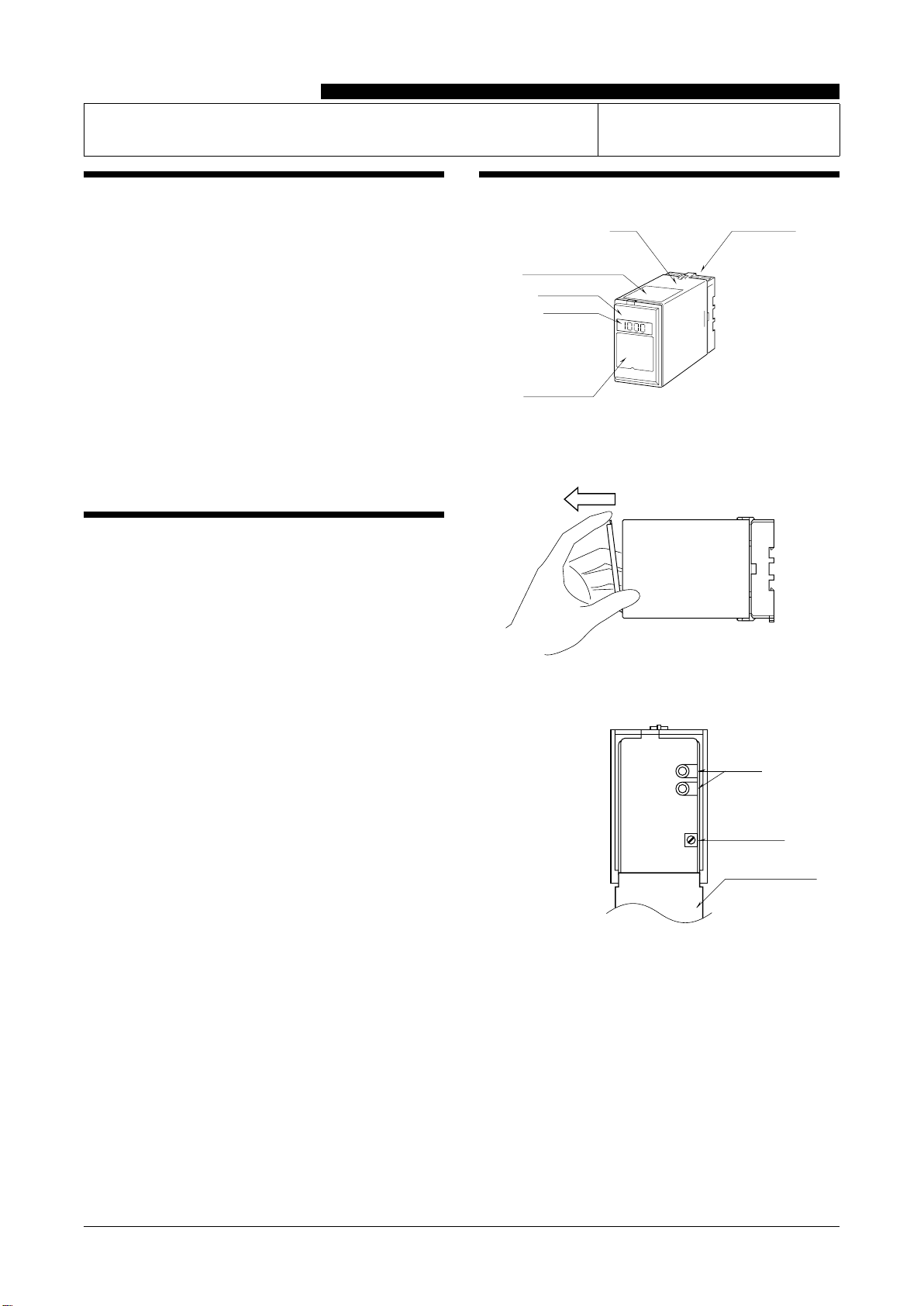
COMPONENT IDENTIFICATION
Body Base Socket
Connection Diagram
Front Cover
LCD Meter
(optional)
Specifications
■HOW TO OPEN THE FRONT COVER:
Hang your finger on the hook at the top of the front cover
and pull.
The shape of base socket may be different
for some models.
■STANDARD TYPE: MONITOR JACKS
Front Cover (open)
Setpoint Adj.
+
–
Monitor
• Monitor jacks for setpoint adjustment
0 – 10V DC is output in proportion to 0 – 100% output set-
points. Insert a tester with a diameter of 2.0 mm (.08”) into
the monitor jack to check the output value. For example, in
order to output 12mA with output 4 – 20mA DC, adjust the
setpoint so that the monitor output becomes 5V.
• Setpoint adjustment
Adjust the setpoint while checking the monitor output.

MS
EM-1651 Rev.8 P. 2 / 2
MG CO., LTD. www.mgco.jp
5-2-55 Minamitsumori, Nishinari-ku, Osaka 557-0063 JAPAN
■OPTION /E: LCD METER
Front Cover (open)
Setpoint Adj.
LCD Meter
• LCD Meter
Output value is displayed in 0 to 100%.
• Setpoint adjustment
Adjust the setpoint while checking a value displayed on the
LCD meter.
Default setting: 0%
INSTALLATION
Detach the yellow clamps located at the top and bottom of
the unit for separate the body from the base socket.
Clamp
(top & bottom)
DIN Rail
35mm wide
Spring Loaded
DIN Rail Adaptor
Shape and size of the base socket
are slightly different with various
socket types.
■DIN RAIL MOUNTING
Set the base socket so that its
DIN rail adaptor is at the bot-
tom. Hang the upper hook at
the rear side of base socket on
the DIN rail and push in the
lower. When removing the
socket, push down the DIN
rail adaptor utilizing a minus
screwdriver and pull.
■WALL MOUNTING
Refer to “EXTERNAL DI-
MENSIONS.”
TERMINAL CONNECTIONS
Connect the unit as in the diagram below or refer to the connection diagram on the top of the unit.
■EXTERNAL DIMENSIONS unit: mm (inch)
3456
2187
80 (3.15)
50 (1.97) 107 (4.21)
127 (5) [3.3 (.13)]
80 (3.15)
20
(.79)
40 (1.57)
50 (1.97)
7.8 (.31)
CLAMP
(top & bottom)
DIN RAIL
35mm wide
2–4.5 (.18) dia.
MTG HOLE
15 (.59) deep
8–M3.5
SCREW
• When mounting, no extra space is needed between units.
■CONNECTION DIAGRAM
+
–
OUTPUT
1
2
U(+)
V(–)
POWER
7
8
CHECKING
1) Terminal wiring: Check that all cables are correctly con-
nected according to the connection diagram.
2) Power input voltage: Check voltage across the terminal
7 – 8 with a multimeter.
3) Output: Check that the load resistance meets the de-
scribed specifications.
LIGHTNING SURGE PROTECTION
We offer a series of lightning surge protector for protec-
tion against induced lightning surges. Please contact us to
choose appropriate models.
Other MG Portable Generator manuals


