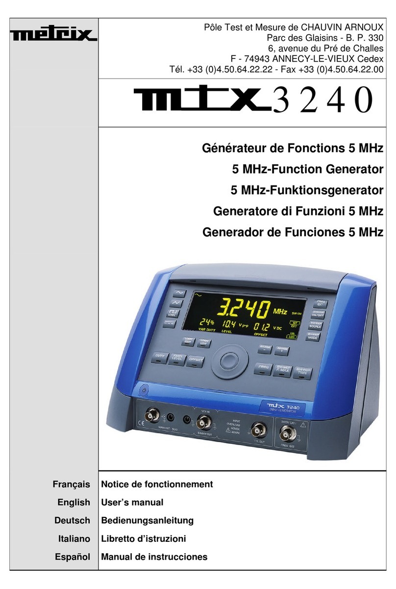
Metrix GX 305 User manual

Function
Generators
G
GG
G
G
GG
G
G
GG
GX
XX
X
X
XX
X
X
XX
X
3
33
3
3
33
3
3
33
30
00
0
0
00
0
0
00
05
55
5
5
55
5
5
55
5
G
GG
G
G
GG
G
G
GG
GX
XX
X
X
XX
X
X
XX
X
3
33
3
3
33
3
3
33
31
11
1
1
11
1
1
11
10
00
0
0
00
0
0
00
0
-
--
-
-
--
-
-
--
-
G
GG
G
G
GG
G
G
GG
GX
XX
X
X
XX
X
X
XX
X
3
33
3
3
33
3
3
33
31
11
1
1
11
1
1
11
10
00
0
0
00
0
0
00
0P
PP
P
P
PP
P
P
PP
P
G
GG
G
G
GG
G
G
GG
GX
XX
X
X
XX
X
X
XX
X
3
33
3
3
33
3
3
33
32
22
2
2
22
2
2
22
20
00
0
0
00
0
0
00
0
-
--
-
-
--
-
-
--
-
G
GG
G
G
GG
G
G
GG
GX
XX
X
X
XX
X
X
XX
X
3
33
3
3
33
3
3
33
32
22
2
2
22
2
2
22
20
00
0
0
00
0
0
00
0E
EE
E
E
EE
E
E
EE
E
U
U
Us
s
se
e
er
r
r’
’
’s
s
s
m
m
ma
a
an
n
nu
u
ua
a
al
l
l
Pôle Test et Mesure de CHAUVIN-ARNOUX
Parc des Glaisins - 6, avenue du Pré de Challes
F - 74940 ANNECY-LE-VIEUX
Tel. +33 (0)4.50.64.22.22 - Fax +33 (0)4.50.64.22.00
Copyright © X03218E02 - Ed. 01- 04/14

Contents
I - 2 Function Generators
Contents
C
C
Ch
h
ha
a
ap
p
pt
t
te
e
er
r
r
I
II
General Instructions ............................................................................................................................................. 4
Introduction.........................................................................................................................................................4
Contents of the box............................................................................................................................................4
Precautions ........................................................................................................................................................4
Safety measures ................................................................................................................................................4
Guarantee ..........................................................................................................................................................5
Maintenance, metrological checks.....................................................................................................................5
Maintenance.......................................................................................................................................................5
C
C
Ch
h
ha
a
ap
p
pt
t
te
e
er
r
rII
GX 305 and GX 310 Description...........................................................................................................................6
Presentation.......................................................................................................................................................6
Specifications..................................................................................................................................................6
Front Face..........................................................................................................................................................6
Back Face .......................................................................................................................................................... 7
Display................................................................................................................................................................7
Keys....................................................................................................................................................................9
Pressing keys for less than < 1s.....................................................................................................................9
Pressing keys for more than > 1s.................................................................................................................11
C
C
Ch
h
ha
a
ap
p
pt
t
te
e
er
r
r
I
III
III
II
GX 320 Description ............................................................................................................................................. 12
Presentation.....................................................................................................................................................12
Specifications................................................................................................................................................12
Front Face........................................................................................................................................................12
Back Face ........................................................................................................................................................ 13
Display..............................................................................................................................................................13
Keys..................................................................................................................................................................16
Pressing keys for less than < 1s...................................................................................................................17
Pressing keys for more than > 1s.................................................................................................................18
Chapter IV
General commands............................................................................................................................................. 19
Commissioning.................................................................................................................................................19
in Normal mode ............................................................................................................................................19
in Version mode............................................................................................................................................19
in Calibration mode.......................................................................................................................................19
in Autotest mode...........................................................................................................................................19
Stop..................................................................................................................................................................20
Activating MAIN OUT.......................................................................................................................................20
Adjusting screen contrast.................................................................................................................................21
Selection of the instrument function.................................................................................................................21
Display of the software version ........................................................................................................................22
Automatic calibration........................................................................................................................................22
Instrument Autotest..........................................................................................................................................25
Saving a configuration (GX 320)......................................................................................................................28
Reloading a configuration (GX 320).................................................................................................................29
Clearing a configuration (GX 320)....................................................................................................................30
C
C
Ch
h
ha
a
ap
p
pt
t
te
e
er
r
r
V
V
V
Generation of simple CONTinuous periodical signals....................................................................................31
Available output signals....................................................................................................................................31
Signal selection................................................................................................................................................31
Adjusting signal frequency ............................................................................................................................... 32
Adjusting signal duty cycle ...............................................................................................................................35
Adjusting signal amplitude................................................................................................................................35
Adjusting offset and DC level...........................................................................................................................36
Adjusting signal logical levels...........................................................................................................................36

Contents
Function Generators I - 3
C
C
Ch
h
ha
a
ap
p
pt
t
te
e
er
r
r
V
V
VI
II
SHIFT Shift Keying function (GX 320 only)....................................................................................................... 37
Connections .....................................................................................................................................................37
Selection of FSK mode.....................................................................................................................................37
Selection of PSK mode ....................................................................................................................................37
Selection of piloting source ..............................................................................................................................37
Adjusting jump frequencies (in FSK mode)......................................................................................................38
Adjusting jump phases (in PSK mode).............................................................................................................38
Other settings...................................................................................................................................................38
C
C
Ch
h
ha
a
ap
p
pt
t
te
e
er
r
r
V
V
VI
III
II
SWEEP Frequency scan function...................................................................................................................... 39
Connections .....................................................................................................................................................39
Selection of the sweep mode...........................................................................................................................39
Selection of the scan source............................................................................................................................40
Adjusting START / END frequencies ...............................................................................................................40
Adjusting scan period using an INTernal source..............................................................................................41
Other settings...................................................................................................................................................41
C
C
Ch
h
ha
a
ap
p
pt
t
te
e
er
r
r
V
V
VI
III
III
II
MODUL Modulation function (GX 320 only) ..................................................................................................... 42
Connections......................................................................................................................................................42
Selection of AM / FM mode..............................................................................................................................42
Selection of the modulation source..................................................................................................................43
Adjustment of the FM START / END frequencies............................................................................................43
Other settings...................................................................................................................................................43
C
C
Ch
h
ha
a
ap
p
pt
t
te
e
er
r
r
I
IIX
X
X
FREQ Frequency meter function ....................................................................................................................... 44
Connections.....................................................................................................................................................44
C
C
Ch
h
ha
a
ap
p
pt
t
te
e
er
r
r
X
X
X
SYNC Synchronisation function (GX 320 only)................................................................................................ 45
Connections.....................................................................................................................................................45
Selection of SLAVE / MASTER mode.............................................................................................................46
Adjusting dephasing........................................................................................................................................46
Activating signal generation (MASTER) ..........................................................................................................47
Other settings..................................................................................................................................................48
C
C
Ch
h
ha
a
ap
p
pt
t
te
e
er
r
r
X
X
XI
II
GATE function (GX 320 only) ............................................................................................................................. 50
Connections.....................................................................................................................................................50
Activation, Deactivation of GATE ....................................................................................................................50
C
C
Ch
h
ha
a
ap
p
pt
t
te
e
er
r
r
X
X
XI
III
II
BURST pulse burst function (GX 320 only)...................................................................................................... 51
Connections.....................................................................................................................................................51
Selection of the BURST source.......................................................................................................................51
Setting the number of pulses...........................................................................................................................52
Setting the generation time for INTernal source..............................................................................................52
Manual triggering in EXTernal source.............................................................................................................52
Other settings..................................................................................................................................................52
C
C
Ch
h
ha
a
ap
p
pt
t
te
e
er
r
r
X
X
XI
III
III
II
Remote programming (programmable device only)........................................................................................ 53
C
C
Ch
h
ha
a
ap
p
pt
t
te
e
er
r
r
X
X
XI
IIV
V
V
Technical specifications..................................................................................................................................... 56
C
C
Ch
h
ha
a
ap
p
pt
t
te
e
er
r
r
X
X
XV
V
V
General, Mechanical specifications............................................................................................................. 60, 61
C
C
Ch
h
ha
a
ap
p
pt
t
te
e
er
r
r
X
X
XV
V
VI
II
Supplies................................................................................................................................................................ 62

General Instructions
I - 4 Function Generators
General Instructions
Introduction You have just purchased a GX 305, GX 310 or GX 320 Function Generator
and we appreciate your confidence.
Content of the box •the generator
•the safety notice
•the power supply cable
•the USB A/B cable for the programmable versions
•the ETHERNET cable for the GX 320E
•the CD-ROM containing:
the operating guide in 5 languages
the programming in 2 languages
the USB ‘CP210x USB to UART Bridge Controller’ Drivers
the LabView and LabWindows Drivers
the USBxPress application (USB port identification)
the GX320E-Admin (IP address programming)
Precautions To obtain the best service:
- read this notice carefully,
- respect the safety instructions.
Failure to respect the warnings and/or usage instructions may damage the
device and/or installations and may be dangerous for the user.
Safety measures This instrument complies with the NF EN 61010-1 - Ed. 2 (2001) safety
standard relating to the safety of electric measurement devices.
•It is designed for indoor use in an level 2 pollution environment at an altitude
of less than 2000 m, a temperature between 0°C and 40°C and a RH
(relative humidity) of less than 80% up to 40°C.
•The MAIN OUT, SWEEP OUT, TTL OUT outlets are referenced to earth and
protected from accidental voltages that are not in excess of 60 V DC or
40 V AC.
•The FREQ EXT entry can only be used for measurements on Category 1
installations and for voltages not exceeding 300 V in relation to the earth.
•Mains power supply: 115 V or 230 V depending on the model.
Definition of
installation
categories
CAT I: Category I corresponds to measurements on circuits that are not
directly connected to the network.
Example: protected electronic circuits
CAT II: Category II corresponds to measurements
on circuits that are directly
connected to low voltage installations.
Example: power supply for household appliances and portable tools
CAT III: Category III corresponds to measurements on the building
installation.
Example: power supply for industrial machinery or devices.
CAT IV: Category IV corresponds to measurements at the source of the low
voltage installation.
Example: power supply

General Instructions
Function Generators I - 5
General Instructions (contd.)
Symbols on the
instrument Warning: potential hazard, refer to the operating guide.
Selective waste sorting for recycling electric and electronic waste. In
compliance with the WEEE 2002/96/EC directive:
the device should not be considered as household waste.
Earth terminal
Alternating signal
Indication of a key double function when pressed for more than 1
second
USB symbol
Guarantee
This equipment is guaranteed for all manufacturing and parts defects in
compliance with the general terms and conditions which are available on request
During the warranty period (3 years), the instrument may only be repaired by the
manufacturer who reserves the right to make the decision to either repair or
replace all or part of the appliance. In the event of a return of the equipment to
the manufacturer the shipping charge from the customer to the manufacturer is
at the customer’s expense.
The guarantee does not apply in the following conditions:
•inappropriate use of the equipment or use with incompatible equipment
•one or more changes made to the equipment without prior explicit
authorisation from the manufacturer’s technical department
•an intervention is made on the instrument by a person not approved by the
manufacturer
•the adapting to a specific application that is not part of the definition of the
instrument or in the operating guide
•damage caused by a mechanical shock, by dropping the instrument or by
flooding.
Maintenance,
repairs, metrological
checks
The device includes no parts that can be replaced by the operator. All operations
must be carried out by competent approved personnel.
For checks and calibrations, contact one of our accredited metrology laboratories
(information and contact details available on request), at our Chauvin Arnoux
subsidiary or the branch in your country.
Cleaning No interventions are authorised inside the instrument.
- Turn the instrument off (remove the power supply cable).
- Clean using a damp cloth and soap.
- Never use abrasive products or solvents.
- Dry quickly using a dry cloth or an air blower at max. 80°C.

GX 305 and GX 310 Description
II - 6 Function Generators
GX 305 and GX 310
Description
Presentation
The GX 305 and GX 310 are alternating standard form wave generators, using the
DDS (Direct Digital Synthesis) technology. They may simulate the operation and
specifications of various electronic systems.
They also include a frequency meter input.
The GX 310P is a generator that can be programmed remotely via an USB link.
Specifications
- Wave form: sinusoidal, square, triangle, logical, TTL, continuous
- Wave frequency: GX 305 0.001 Hz to 5 MHz for the sinus and the square
0.001 Hz to 2 MHz for the triangle
GX 310 0.001 Hz to 10 MHz for the sinus and the square
0.001 Hz to 2 MHz for the triangle
- INT and EXT sweep: GX 305 adjustable from 0.001 Hz to 5 MHz
GX 310 adjustable from 0.001 Hz to 10 MHz
- EXT freq. meter : from 5 Hz to 100 MHz
Front face
Terminals
1.
MAIN OUT
- Main output
2.
VCF IN
- SWEEP input pilot signal in EXTernal source
SWEEP OUT
- Pilot output signal for INTernal SWEEP
3.
TTL OUT
- TTL output
4.
FREQ EXT
- Frequency meter input
Coding wheel
3.
2.
1.
4.
Back lit LCD display (124 x 43 mm)
ON /
STANDBY

GX 305 and GX 310 Description
Function Generators II - 7
GX 310 Description (contd.)
Back face
GX 305
GX 310
GX 310P
Display
USB type B connection
Network connection
Working voltage indicator
Network connection
Working voltage indicator

GX 305 and GX 310 Description
II - 8 Function Generators
GX 305 and GX 310 Description (contd.)
Wave selection:
•Sinusoidal
•square
•logic
•triangle
•continuous
Indication of the displayed frequency:
•Freq, FreqSTART or FreqEND
•Time (sweep interval)
Frequency display (digit height: 20 mm)
Underscores: Indication of the digit to which the wheel
increments apply during adjustment.
Unit of measure display
•degree
•MHz, kHz, Hz
•seconds
Function selection: current function indicator
•continuous
•sweep
•frequency
Duty cycle value display
Display of the amplitude value
Display of the offset value or the DC level
OFFSET display
DUTY display
AMPLITUDE display
Logical HIGH / LOW display
INTernal / EXTernal source selection
LINear / LOGarithmic sweep display
Sawtooth or triangle type sweep
Indication that the MODE key is assigned:
•to trigger the adjustment step when calibrating
•to trigger the selected test in Autotest
During calibration the is assigned to saving the parameters.

GX 305 and GX 310 Description
Function Generators II - 9
GX 305 and GX 310 Description (contd.)
Keys
The keys with the
symbol have a specific action when pressed for more
than 1 second.
•The white keys may have a backlight:
Appliance under power but not turned on
Appliance turned on
MAIN OUT
Key lit MAIN OUT exit activated
•The other keys can be:
unlit
keys not assigned to the wheel adjustment or
having no action
lit
the corresponding adjustment is assigned to the
wheel.
blinking
the corresponding adjustment can be assigned to
the wheel.
Each time the WAVEFORM or FUNCTION is changed the keys that can be
assigned to the wheel adjustment blink for 4 seconds; if no keys are used
at this time the frequency adjustment (Freq or Freq
START
) is assigned to the
wheel.
Keys pressed for
less than 1 second
Sinusoidal waveform selection
Selects square or logical waveform by successive pressing on the key
Triangular waveform selection or saves adjustments during calibration
Continuous waveform selection
MAIN OUT
Validation, or not, of the waveform on the MAIN OUT BNC
Adjustment of the duty cycle using the wheel (square, triangle)
Adjustment of the output signal amplitude using the wheel
•Offset adjustment using the wheel
•DC level adjustment if the continuous
waveform is selected.

GX 305 and 310 Description
II - 10 Function Generators
GX 305 and GX 310 Description (contd.)
Keys pressed for
less than 1 second
(contd.)
LOGIC LEVEL
LOGIC waveform selected:
Adjustment of the high or low signal level using the wheel
FUNCTION
FUNCTION keys:
Selection of one of the three available functions
SWEEP selection of the INTernal or EXTernal command signal
•SWEEP activated: selection of LIN or LOG sweep
•calibration: triggering of the selected adjustment step
•Autotest: run the selected test
SWEEP function activated in INT: assignment of the desired duration setting
for carrying out the sweep using the wheel.
Then, by pressing several times, selection of the digit on which to increment.
Division or multiplication by 10 of the current frequency value (decade change)
•Assignment of frequency adjustment to the wheel.
Then, by pressing several times, selection of the digit on which to
increment.
•SWEEP function activated: same functions with FreqSTART and FreqEND
frequencies.

GX 305 and GX 310 Description
Function Generators II - 11
GX 305 and GX 310 Description (contd.)
Keys pressed for
more than 1 second
Pressing the key for more than 1 second forces the duty cycle to 50%.
Pressing the key for more than 1 second switches from a peak to peak
amplitude display to an RMS (root mean square) display.
Pressing the key for more than 1 second forces the offset value to 0.
LOGIC LEVEL
Pressing the key for more than 1 second assigns the LCD contrast adjustment
to the wheel.
For the SWEEP function, pressing the key for more than 1 second switches
from FreqSTART to FreqEND and vice versa.
These keys assign the selected frequency to the start or end of the current
range.
Ranges Press > 1 Second
‘RANGE-’ Press > 1 second
‘RANGE+’
[0.001 Hz ; 0.01 Hz] 0.001 Hz 0.01 Hz
[0.01 Hz ; 0.1 Hz] 0.01 Hz 0.1 Hz
[0.1 Hz ; 1 Hz] 0.1 Hz 1 Hz
[1 Hz ; 10 Hz] 1 Hz 10 Hz
[10 Hz ; 100 Hz] 10 Hz 100 Hz
[100 Hz ; 1 kHz] 100 Hz 1 kHz
[1 kHz ; 10 kHz] 1 kHz 10 kHz
[10 kHz ; 100 kHz] 10 kHz 100 kHz
[100 kHz ; 1 MHz] 100 kHz 1 MHz
GX 305[1 MHz ; 5 MHz]
GX 310[1 MHz ; 10 MHz]
1 MHz GX 3055 MHz
GX 31010 MHz

GX 320 Description
III - 12 Function Generators
GX 320
Description
Presentation
The GX 320 is a standard alternating signal generator, using the DDS (Direct Digital
Synthesis) technology. It may simulate the operation and the specifications of various
electronic systems. It also includes a frequency meter input. The GX 320E is remote
programmable via an USB or ETHERNET link.
Specifications
- Wave form: sinusoidal, square, triangle, logical, TTL, continuous
- Wave frequency: 0.001 Hz to 20 MHz for the sinusoidal and square
0.001 Hz to 2 MHz for the triangle
- INT and EXT sweep: adjustable from 0.001 Hz to 20 MHz
- EXT frequency meter: from 5 Hz to 100 MHz
- AM modulation: internal (1 kHz) and external (< 5 kHz)
- FM modulation: internal (1 kHz) and external (< 15 kHz)
- Frequency Shift Keying FSK: internal (1 kHz) and external (< 1 MHz)
- Phase Shift Keying PSK : internal (1 kHz) and external (< 1 MHz)
- BURST function: internal or external (< 1 MHz)
- GATE function: external (< 2 MHz)
- Function to synchronise several generators
- 15 configurations can be saved and recalled
Front face
Terminals
1.
MAIN OUT
- Main output
2.
VCG IN
- External SWEEP, MODUL, SHIFT K, BURST piloting signal input
SYNC CTRL
- Master synchronisation output signal in SYNC function
- Slave synchronisation input signal in SYNC function
SWEEP OUT in SWEEP or SHIFT K INTernal source
- Sweep piloting output signal for FSK and PSK
3.
TTL OUT
- TTL output
SYNC M CLK
- in SYNC function, master clock output
4.
FREQ EXT
- Frequency meter input
SYNC S CLK
- in SYNC function, slave synchronisation clock input
GATE IN
- GATE piloting input signal
Coding wheel
Back lit LCD display (124 x 43 mm)
ON / STANDBY
1. 2. 3. 4.

GX 320 Description
Function Generators III - 13
GX 320 Description (contd.)
Rear panel
GX 320
GX 320E
Display
USB type B
connection
Network
Connection
Indication of the
working
voltage
ETHERNET
USB type B connection
Network
Conne
ct
ion
Indication of the
working
voltage

GX 320 Description
III - 14 Function Generators
GX 320 Description (contd.)
Signal selection:
•sinusoidal
•square
•logic
•triangle
•continuous
current waveform indicator
Display of the current frequency phase:
•Freq, FreqSTART and FreqEND
•Phase, PhaseSTART, PhaseEND
•Time (sweep period, pulse period)
•Num : number of pulses
Frequency display (digit height 20 mm)
Underscores:
Indicate to which digit the wheel increments apply during
adjustment.
Unit of measure display:
•degree
•MHz, kHz, Hz
•seconds
Function selection:
•continue
•Shift Key
•sweep
•modulation
•frequency meter
•synchronisation
•Burst
Current function indicator
Duty cycle value display
Amplitude value display
Offset value or DC level value display
OFFSET type display
DUTY type display
AMPLITUDE type display

GX 320 Description
Function Generators III - 15
GX 320 Description (contd.)
HIGH / LOW level logical type display
INTernal / EXTernal source selection
Mode display:
•AM / FM Modulation
•LINear / LOGarithmic sweep
•Master / Slave synchronisation
•Shift key Frequency / Phase
Indication that the MODE key is assigned:
•to triggering the adjustment step when calibrating
•to the manual triggering of a set of pulses in BURST mode
•to triggering the selected test in Autotest mode
Sawtooth or triangle sweep type
Modulation rate display AM 20 % or 80 %
GATE mode activated display
Master synchronisation activated display
Slave synchronisation activated display
For the synchronisation function: indicates that the frequency and phase
adjustment on the slave are restricted by the master.
•During calibration the key is assigned to saving the settings.
•In normal mode selects save configuration mode
Selects configuration recall mode
Selects configuration clearing mode

GX 320 Description
III - 16 Function Generators
GX 320 Description (contd.)
Keys
Keys with the symbol have a specific action when pressed for more than
1 second.
•The white keys may have a back light:
Appliance under power but not turned on (red)
Appliance turned on (green)
MAIN OUT
Key lit MAIN OUT exit activated
MAIN OUT
Blinking key MAIN OUT and GATE functions activated
•The other keys can be:
unlit keys not assigned to the wheel adjustment or having no
action
lit the corresponding adjustment is assigned to the wheel.
blinking
the corresponding adjustment can be assigned to the
wheel.
Each time the WAVEFORM or FUNCTION is changed the keys that
can be assigned to the wheel adjustment blink for 4 seconds; if no
keys are used at this time the frequency adjustment (Freq or
FreqSTART) is assigned to the wheel.
Keys pressed for
less than 1 second
WAVEFORM
WAVEFORM keys:
Selects the waveform to be generated
Saves the current configuration or saves the settings when calibrating
Recalls or clears a saved configuration

GX 320 Description
Function Generators III - 17
GX 320 Description (contd.)
Keys pressed for
less than 1s (contd.)
Validation or not of the wave on the MAIN OUT BNC.
Adjustment of the wave duty cycle (square, triangle) using the wheel.
Adjustment of the output wave amplitude using the wheel.
•Offset adjustment using the wheel.
•Adjustment of the DC level if the continuous waveform is selected.
LOGIC LEVEL
LOGIC waveform selected: adjustment of the high or low wave level using the
wheel.
FUNCTION
FUNCTION keys:
Selection of one of the 7 available functions.
SHIFT K, or SWEEP, or MODUL or BURST functions activated: selection of
the INTernal or EXTernal command signal.
•SHIFT K or SWEEP or MODUL or SYNC functions activated: selection of
a specific function mode (see Function list and adjustment paragraph).
•BURST function and EXTernal source activated: manual triggering of a
set of pulses.
•calibration: triggers the selected adjustment step.
•Autotest: triggers the selected test.
•SWEEP activated with INTernal source: assignment of the wheel to the
desired timing adjustment to carry out a frequency sweep; then, by
pressing several times, selection of the digit on which to apply the
increment.
•BURST function active: assignment of the wheel to the adjustment of the
number of pulses or the burst generation period (INT source); then, by
pressing several times, selection of the digit on which to apply the
increment.
Division or multiplication by 10 of the current frequency value (decade change).
•Assignment of frequency adjustment to the wheel; then, by pressing
several times, selection of the digit on which to apply the increment.
•SWEEP or MODUL FM or FSK activated: same functions with the
FreqSTART and Freqend frequencies.
•SYNC function activated: adjustment of the de-phasing between the two
generators using the wheel.
•PSK function activated: by pressing several times, adjustment of the
PhaseSTART or Phaseend using the wheel.

GX 320 Description
III - 18 Function Generators
GX 320 Description (contd.)
Keys pressed for
more than 1 second
Pressing for more than 1 second sets the GATE function.
Pressing for more than 1 second forces the duty cycle to 50 %.
Pressing the key for more than 1 second switches from a peak to peak
amplitude display to an RMS (root mean square) display.
Pressing the key for more than 1 second forces the offset value to 0.
LOGIC LEVEL
LOGIC LEVELLOGIC LEVEL
LOGIC LEVEL
Pressing the key for more than 1 second assigns the LCD contrast adjustment
to the wheel.
BURST function activated, INTernal source. Pressing the key for more than 1
second is used to switch the number of pulses Num in the pulse generation
period Time, and vice versa.
These keys assign the selected frequency to the start or end of the current
range.
Ranges Press > 1 Second
‘RANGE-’ Press > 1 second
‘RANGE+’
[0.001 Hz ; 0.01 Hz] 0.001 Hz 0.01 Hz
[0.01 Hz ; 0.1 Hz] 0.01 Hz 0.1 Hz
[0.1 Hz ; 1 Hz] 0.1 Hz 1 Hz
[1 Hz ; 10 Hz] 1 Hz 10 Hz
[10 Hz ; 100 Hz] 10 Hz 100 Hz
[100 Hz ; 1 kHz] 100 Hz 1 kHz
[1 kHz ; 10 kHz] 1 kHz 10 kHz
[10 kHz ; 100 kHz] 10 kHz 100 kHz
[100 kHz ; 1 MHz] 100 kHz 1 MHz
[1 MHz ; 10 MHz] 1 MHz 10 MHz
[10 MHz ; 20 MHz] 10 MHz 20 MHz
For the SWEEP or MODUL FM or FSK functions pressing the key for more
than 1 second is used to switch between FreqSTART and FreqEND and vice versa.

General Commands
Function Generators IV - 19
General Commands
Commissioning
Check that your instrument is compatible with the mains network voltage
(see the label at the back of the instrument), that the power supply cable
is not damaged and that it is earthed.
The power supply cable plug is used as a cut off point, connect the device
to a mains outlet that is easily accessible and is earthed in order to
ensure safety.
Four start-up modes are possible depending on the key – or combination of
keys - used:
1. Normal Mode:
The instrument starts up using the last used configuration. By default the
factory configuration is restored.
The key becomes:
2. Version Mode:
+
The instrument starts up in Version mode and displays the current software
version number and date.
The key becomes: (See Display of the software version).
3. Calibration Mode:
FUNCTION
+
The instrument starts up in Calibration mode with the selection of the
calibration to be run: automatic mode CAL_AU, by default.
The key becomes: (See automatic calibration).
4. Autotest Mode:
MAIN OUT
+
The instrument starts up in Autotest mode with the selection of the test to
be run: automatic mode tSt_AU by default.
The key becomes: (See Autotest).

General Commands
IV - 20 Function Generators
General Commands (contd.)
Stop
Whatever the mode, pressing this key puts the instrument on STANDBY.
When pressed while in Normal mode the context is saved:
- current settings in use for signal generation when the instrument was
stopped,
- settings for other functions that may have been changed.
The key becomes:
Each time Normal mode start-up is used all the settings are reloaded.
In the event of a power failure (or if the power cable is unplugged …), the
instrument restarts using the last backup (backup made the last time the device
was turned off using the ON/STANDBY key).
In the event of an error the default configuration is loaded:
•Signal sinusoidal
•Function CONTinuous
•Frequency 1 kHz
•Amplitude 1 Vpp
•Offset 0 V
•Output MAIN OUT ON not active
•No adjustments assigned to the wheel.
The key becomes: .
Activating the
MAIN OUT terminal
At start-up the MAIN OUT terminal is always de-activated.
MAIN OUT
Pressing the key activates the terminal and the key lights: .
On the GX 320: the key may blink when the GATE function is activated (see
GATE function).
MAIN OUT
De-activation of the MAIN OUT terminal, the key is no longer lit: .
This manual suits for next models
4
Table of contents
Other Metrix Portable Generator manuals
Popular Portable Generator manuals by other brands

King Canada
King Canada Power Force KCG-5625G instruction manual

ECOBOXX
ECOBOXX 1500 manual

Honeywell
Honeywell G0060651 Operator's manual
Enterasys
Enterasys BL-89451ENT user guide
Yamaha
Yamaha EF2400iS - Inverter Generator owner's manual

CAC / BDP
CAC / BDP FOR BYPASS AND FAN POWERED HUMIDIFIERS Diagnostic repair manual
