Fiber Options 9900V-T User manual

SERIES 9900V: SINGLE-MODE DIGITAL VIDEO MULTIPLEXERS
DESCRIPTION
A 9900V link supports from 2 to 10 video channels while
the 9900VD link also supports one channel of data. The
High Capacity version of the 9900V can support from 12 to
20 channels of video. The 9900V-T transmitter consists of
a single 1-RU (rack unit) module with up to 10 video inputs
and one fiber output. All video channels are transmitted
over single-mode fiber to the 9900V-R receiver, which con-
sists of a single 1-RU module with one fiber input and from
2 to 10 video outputs. 9900VD models include one return
data output connection as well. High capacity 9900V mod-
els consist of two interconnected 1-RU units on both the
transmit and receive ends of the system with a total of from
12 to 20 video connections. For a complete list of available
models, please turn to the last page.
INSTRUCTION
MANUAL
FIGURE 1: SYSTEM DIAGRAM 9900V & 9900VL MODELS
one single-mode
optical fiber
from two
to twenty
video inputs
from two
to twenty
video outputs
9900V-T
9900V-R
FIGURE 2: SYSTEM DIAGRAM 9900VD MODELS
one or two single-mode
optical fibers
from two to ten
video inputs
one
data ouput
from two to ten
video outputs
one
data input
9900VD-T
9900VD-R
www.fiberoptions.com
Fiber Options 80 Orville Drive, Bohemia, NY 11716
GENERAL
This manual is a guide to the installation and operation of
the 9900V series fiber optic digital video transmission
system and 9900VD series fiber optic digital video with
return data transmission system. Please read the entire
manual before installing the equipment.
Note: The series numbers 9900V-T and 9900V-R will be
used to describe all models of transmitters and receivers
unless noted otherwise.
The 9900V-T transmitter consists of a single 1-RU (rack
unit) module with from 2 to 10 video inputs and one fiber
output. The 9900V-R receiver unit has one fiber input
and from 2 to 10 video outputs.
The 9900VD-T transmitter has from 2 to 10 video inputs
with 1 data output connection and 1 or two fiber input/out-
puts. The 9900VD-R receiver has 1 or 2 fiber input/out-
puts, from 2 to 10 video outputs, and 1 data input.
Models with from 12 to 20 inputs (9912V to 9920V) con-
sist of two 1-RU modules at each end, joined by an opti-
cal jumper.
LASER SAFETY
CAUTION: Class I Laser Product.
Invisible Radiation at Aperture.
Avoid Exposure to Beam.
Although this is a Class I laser product, which is not con-
sidered hazardous, keep in mind that the beam is invisi-
ble. For your further protection we suggest that you:
✹Do not turn on any transmitter unit unless both ends
of the fiber are connected.
✹Never look into the fiber optic connector on the back
of any unit when the unit is turned on.
✹Never look directly at the end of the fiber optic cable
when the unit is turned on.
✹Do not aim activated fiber optic cable ends at reflec-
tive surfaces or other persons.
. . . light years ahead 11-9900V-000918
!

www.fiberoptions.com
ELECTRICAL SAFETY
In order to protect the user from injury and the product
from damage please note the following.
Grounding
This product is intended to be electrically grounded and is
equipped with a three-wire grounding plug, which fits only
a grounded AC outlet. DO NOT DEFEAT THE PURPOSE
OF THIS GROUNDING PLUG.
INSTALLATION
Unpacking the Unit
In the event that anything is missing from the following list,
contact your authorized Fiber Options dealer or represen-
tative. Save the original packing materials in case it
becomes necessary to return the unit.
Remove all materials from the packing box and confirm
receipt of the following:
9900V-T Transmitter or 9900V-R Receiver
AC Power Cord
Model 648P Power Supply
2 Brackets for Rack or Wall Mounting
4 Screws for attaching Brackets to 9900V
4 Rubber Feet for Desk-top Mounting
Fiber Jumper (Models 9912V - 9920V ONLY)
Instruction manual
GENERAL INSTALLATION
Installation Considerations
You may select any one of three methods of installation,
depending upon the conditions and limitations of the site.
The 9900V series units may be installed in a standard 19-
inch rack, as a desktop unit, or as a wall-mounted unit.
In all cases, after selecting the method of installation and
the location, verify that there is enough space to pull and
connect all cables without stressing them beyond the
manufacturer's minimum bend radius limitation. Also con-
sider future accessability issues when selecting the loca-
tion. Refer to the included engineering drawings for front
and rear panel layouts.
Rack-mount Installation
Using the 4 screws provided, attach the rack-mount tabs
to the 9900V. Locate the vertically aligned mounting holes
on the left and right sides of the unit and position the
round screw-holes on the tabs over them. Be sure that the
oblong screw-holes on the tabs are facing forward and
that the tabs are flush with the front bezel of the unit.
Attach each tab with 2 screws. Do not over-tighten the
screws.
At this point, the 9900V is ready to mount in a standard 19
inch EIA rack, using appropriate screws. Fasten the
9900V to the rack securely, again being sure not to over-
tighten the screws. When installing more than one 9900V
in a rack or in a rack that is partially populated with other
equipment, be sure to provide adequate ventilation
between the units. A minimum of 1 RU (1.75 inches) is
recommended for air flow.
Desk-top Installation
Place the 9900V upside-down on a flat surface being
careful not to scratch the surface of the unit. Wipe the
bottom of the 9900V with a soft, dry cloth to remove any
dust or dirt. Remove the backing from the provided rubber
feet and attach them to the bottom of the 9900V, placing
them approximately 1 inch from each corner of the unit.
Press firmly to ensure a good bond. Turn the 9900V over
FIGURE 3: 9900V SERIES DIMENSIONS (ALL UNITS)
19.0 in (48.3 cm)
with mounting tabs
installed
18.25” (46.4 cm)
1.25 in
(3.2 cm) 1.72 in
(4.4 cm)
17.0 in (43. cm)
2
Note: Depth of all 9900V units = 11.7 inches (29.7 cm)
including panel-mounted BNC connectors.

and place it on the desk-top.
If more than one 9900V is to be installed, repeat the
above process. The 9900V units may be stacked one on
top of another, but should not be stacked higher than 4
units for stability.
Wall-mount Installation
Select the area on the wall where the 9900V will be
installed and determine where the power supply will be
located. Be sure that both an a/c power source and the
9900V will be within reach of the power supply. Also veri-
fy that there will be no excessive strain on the power con-
nection at the 9900V. It is also recommended that the unit
be mounted in such a way that the LED indicators will all
be readily visible.
CAUTION: Do not attempt to attach the 9900V to a dry-
wall surface.
Locate the mounting holes on the left and right sides of
the unit, 2 sets of 2 horizontally aligned holes on each
side. Position the round screw-holes on the tabs over the
mounting holes on the 9900V, being sure that the oblong
screw-holes are flush with the bottom of the unit. Attach
each tab securely to the 9900V with 2 screws, but do not
over-tighten the screws. Refer to Figure 4.
Mount the 9900V to the wall, using 4 screws suitable for
fastening to the selected surface. Use screws that are suf-
ficiently long to provide secure mounting to the wall.
Power Connection
The 9900V series units are supplied with an external DC
power supply, model 648P. A permanently attached cable
is provided for the DC ouput and a detachable three-wire
grounded cable is provided for AC input.
CAUTION:Do not connect the unit to an AC power
source until directed to do so.
1. Remove the detachable screw terminal power con-
nector from the back of the 9900V unit.
2. The external 648P power supply has a pendant cable
with two tinned leads. Connect these leads to
the power connector as shown in Figure 5.
3. Verify that the power supply is not connected to a wall
outlet, and insert the detached power connector into
its socket on the back of the 9900V unit.
See the Electrical Safety section on page 2 for additional
electrical connection information and safety precautions.
Do not plug the power supply into an AC outlet at this
time.
Fiber Optic Cable Connection
Most cable manufacturers identify the individual fibers in
the cable. Select appropriately terminated fiber and mark
both ends with unique identification label (e.g. for cable
no. 03, fiber no. 08) to ensure that the fiber connected to
the near end is the same one that is connected to the far
end.
The proper optical connection will link the transmitter's
OUT port to the receiver's IN port.
www.fiberoptions.com
3
FIGURE 5: DETACHABLE SCREW TERMINAL
POWER CONNECTOR.
FIGURE 4: LOCATION OF BRACKETS FOR WALL
MOUNTING.
To Power Supply
Black (-) Red (+)
Chassis
Ground
Front
Rear
Rear
Front
or
continued on page 5

www.fiberoptions.com
4
FIGURE 6: RJ-45 SOCKET
LOOKING TOWARD THE
REAR OF THE 9900V.
9900V-R models (data transmitters) 9900V-T models (data receivers)
Pin
8 1
RS232 Connection RS232 Connection
Pin No. Function
8nc
7nc
6ground/shield
5tie to pin 6
4RS232 in
3nc
2nc
1nc
Wire Color*
white
orange
black
red
green
yellow
blue
violet
Pin No. Function
8nc
7nc
6ground/shield
5RS232 out
4nc
3nc
2nc
1nc
Wire Color*
white
orange
black
red
green
yellow
blue
violet
RS422 Connection RS422 Connection
Pin No. Function
8nc
7nc
6ground/shield
5nc
4RS422 out +
3RS422 out −
2nc
1nc
Wire Color*
white
orange
black
red
green
yellow
blue
violet
Pin No. Function
8nc
7nc
6ground/shield
5nc
4RS422 in +
3RS422 in −
2nc
1nc
Wire Color*
white
orange
black
red
green
yellow
blue
violet
Manchester/Biphase Connection Manchester/Biphase Connection
Pin No. Function
8nc
7nc
6ground/shield
5nc
4nc
3nc
2Manchester / Biphase out
1Manchester / Biphase out
Wire Color*
white
orange
black
red
green
yellow
blue
violet
Pin No. Function
8nc
7nc
6ground/shield
5nc
4Manchester / Biphase in
3Manchester / Biphase in
2nc
1tie to pin 4
Wire Color*
white
orange
black
red
green
yellow
blue
violet
nc = no connection
6: BLACK
5: RED
3: YELLOW
4: GREEN
2: BLUE
1: VIOLET
7: ORANGE
8: WHITE
FIGURE 7: SCREW-TERMINAL TO RJ-45 CABLE ADAPTER CONNECTIONS
* Wire Color refers to the color of the wire inside the Screw-Terminal to RJ-45 adapter. See Figure 7 above.

www.fiberoptions.com
5
1. Wipe the inside of the port’s sleeve with a lint-free
pipe cleaner moistened with reagent-grade isopropyl
alcohol. Blow dry with dry air.
2. Clean the connector using a lint-free cloth dampened
with alcohol to thoroughly wipe the side and end of
the ferrule. Blow the ferrule dry with dry air. Visually
inspect the ferrule for lint.
3. Fasten the fiber optic cable to the port.
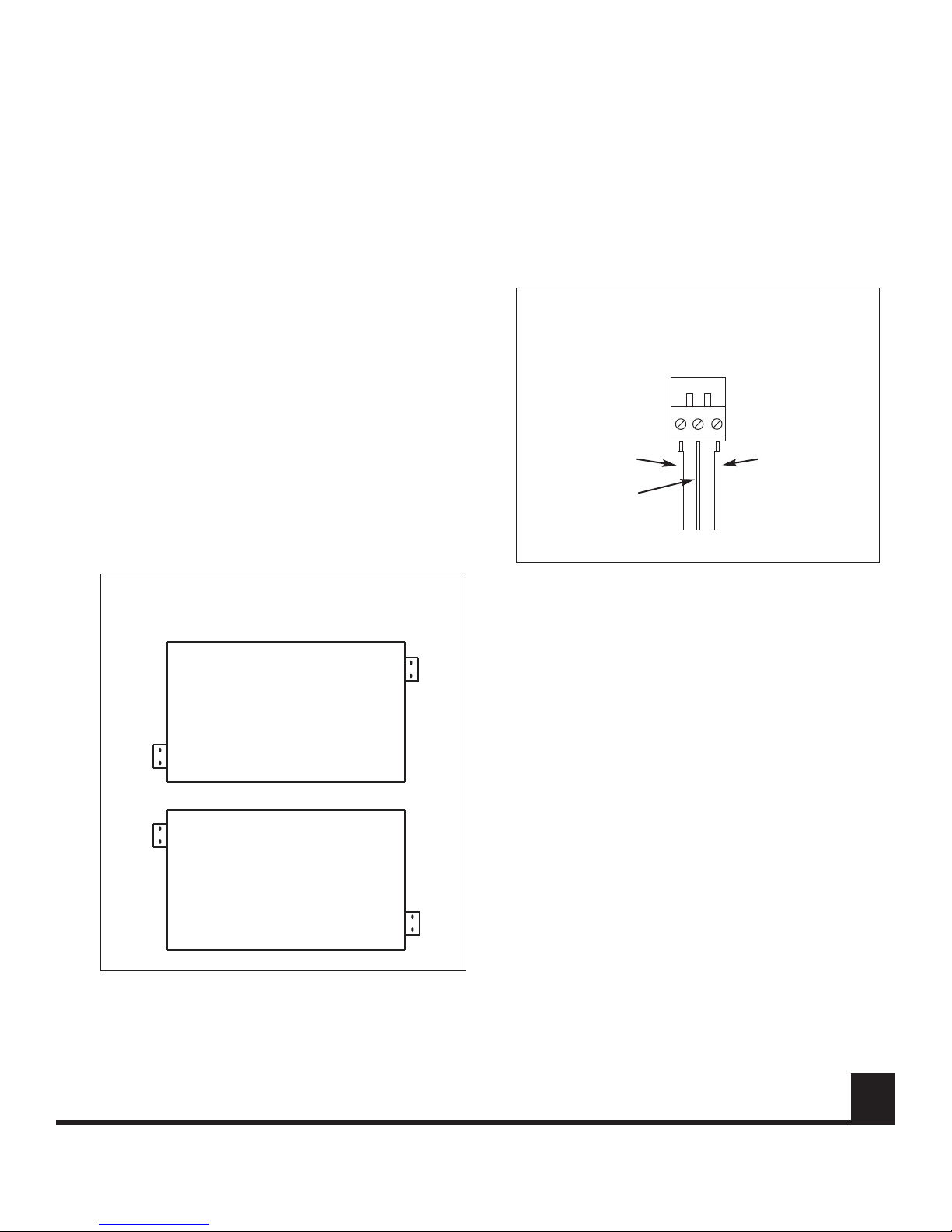
Connecting Channels 12 - 20
Units designed for transmission of more than 10 channels
(9912V - 9920V) consist of two 1-RU units and a fiber
jumper at each end of the link.
One of the two 9900V units will have BNC connections for
channels 1 - 10 . These units are the primary units in the
link and can complete the link with or without the second-
ary units. Secondary units
have BNC connections for
channels 11 and 12 and may
have connections for addition-
al channels, always in pairs,
up to channels 19 and 20.
Primary units have two optical
ports each, one labeled IN
and one labeled OUT.
Secondary units each have
only one optical port, labeled
OUT on the transmitter and IN
on the receiver. At each end of
the link, use the provided fiber
jumper to connect the second-
ary unit’s optical port to the
opposite port on the primary
9900V unit. In other words,
connect OUT to IN, and IN to
OUT (see Figure 8). Both
units at each end of the link
should now be joined with a
fiber jumper. The appropriate
fiber port should be free to
complete the link - OUT on the
transmitter side and IN on the
receiver side.
Video Cables
Video signals are sent over a
75 ohm coaxial cable termi-
nated in a BNC connector
(e.g., RG 59/U with a BNC
connector).
1. At the transmitter end, connect the video source to
one of the numbered VIDEO connectors.
2. At the receiver , connect the corresponding VIDEO
BNC to monitoring equipment.
Data Connection
The 9900VD series units support RS232, RS442,
Manchester, and Biphase data formats. All are connected
a male RJ-45 plug which is then inserted into the corre-
sponding RJ-45 socket on the rear of the 9900VD unit.
Data connection must be made according to the tables on
page 4 depending upon the data format being used. Refer
to Figure 6.
Connection to the RJ-45 plug may also be made using a
cable adapter which is provided with the 9900VD unit.
Refer to Figure 7.
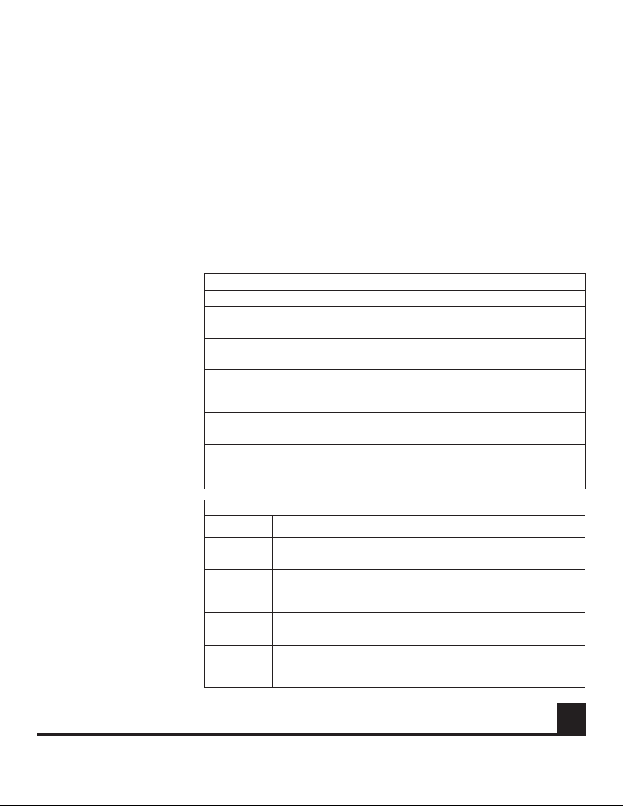
Table 2: Receiver LED Indicators
Green or flashing green - data is being transmitted. No action needed.
Unlit -no data transmitted (not used in 9900V series without data capabili-
ties). Verify that the data input is properly connected and that the data
source is operating properly.
DATA
TX
Green - communication is established with the transmitter. No action.
Unlit - no communication established. Verify that the transmitter is on and
operating and that the fiber is connected to both units.
LINK READY
Green - adequate optical signal received. No action needed.
Red - inadequate optical signal. Check Fiber connection and optical
cable. Verify optical budget is not exceeded. Verify that the transmitting
unit is connected and operating.
LEVEL/
LOSS
Green - AC power is present. No action needed.
Unlit - no power present. Check connection to AC outlet, check outlet for
AC if connection is good.
POWER
Indication - Suggested ActionLED Name
Green - Laser functioning properly. No action needed.
Unlit - laser has failed. Contact Fiber Options technical support for assis-
tance.
LASER
TX
Green - camera (video) signal normal on this channel. No action needed.
Unlit - video is not being received on this channel. Check coaxial cable
input for this channel. Verify that the video source (camera) is operating
and is properly connected.
Table 1: Transmitter LED Indicators
VIDEO
STATUS
Green - Received optical signal is adequate. No action needed.
Unlit - Inadequate optical signal. Check Fiber connection and optical
cable. Verify optical budget is not exceeded. Verify that the transmitting
unit is connected and operating.
DATA
RX
Unused in current models.
Reserved for future use.
COMMAND
TX
Green - AC power is present. No action needed.
Unlit - no power present. Check connection to AC outlet, check outlet for
AC if connection is good.
POWER
Indication - Suggested ActionLED Name

All specifications are subject to change without notice. Information furnished by FIBER OPTIONS is believed to
be accurate and reliable. However, no responsibility or liability is assumed by FIBER OPTIONS for its use, nor
for any infringement of patents or other rights of third parties which may result from its use. No license is grant-
ed by implication or otherwise under any patent or other rights of FIBER OPTIONS.
Copyright 2000 by FIBER OPTIONS.
All rights reserved.
www.fiberoptions.com
Fiber Options 80 Orville Drive, Bohemia, NY 11716
Receivers
Transmitters
Table 3: 9900V Series Model Variations
10
Channels
8
Channels
6
Channels
4
Channels
2
Channels
10
Channels
8
Channels
6
Channels
4
Channels
2
Channels
20
Channels
18
Channels
16
Channels
14
Channels
12
Channels
9920V1-T-R9910VD2L-T-R9910VD2-T-R9910VD1-T-R9910V1L-T-R9910V1-T-R
9918V1-T-R9908VD2L-T-R9908VD2-T-R9908VD1-T-R9908V1L-T-R9908V1-T-R
9916V1-T-R9906VD2L-T-R9906VD2-T-R9906VD1-T-R9906V1L-T-R9906V1-T-R
9914V1-T-R9904VD2L-T-R9904VD2-T-R9904VD1-T-R9904V1L-T-R9904V1-T-R
9912V1-T-R9902VD2L-T-R9902VD2-T-R9902VD1-T-R9902V1L-T-R9902V1-T-R
1 Fiber
1310/1550 nm
20
Channels
18
Channels
16
Channels
14
Channels
12
Channels
9920V1-R-R
9918V1-R-R
9916V1-R-R
9914V1-R-R
9912V1-R-R
1 Fiber
1310/1550 nm
2 Fiber / Data
1550 nm
2 Fiber / Data
1310 nm
1 Fiber / Data
1310/1550 nm
1 Fiber
1550 nm
1 Fiber
1310 nm
9910VD2L-R-R9910VD2-R-R9910VD1-R-R9910V1L-R-R9910V1-R-R
9908VD2L-R-R9908VD2-R-R9908VD1-R-R9908V1L-R-R9908V1-R-R
9906VD2L-R-R9906VD2-R-R9906VD1-R-R9906V1L-R-R9906V1-R-R
9904VD2L-R-R9904VD2-R-R9904VD1-R-R9904V1L-R-R9904V1-R-R
9902VD2L-R-R9902VD2-R-R9902VD1-R-R9902V1L-R-R9902V1-R-R
2 Fiber / Data
1550 nm
2 Fiber / Data
1310 nm
1 Fiber / Data
1310/1550 nm
1 Fiber
1550 nm
1 Fiber
1310 nm
OPERATION
To operate the 9900V or 9900VD transmission
system, connect the power supply to a ground-
ed AC outlet, using the supplied detachable
power cord.
See Tables 1 and 2 below for LED indication
values and suggested corrective actions.
MAINTENANCE
There is no operator maintenance other than
keeping the units clean. Wipe the outside of the
9900V with a damp cloth as needed.
INSTRUCTION
MANUAL
. . . light years ahead 11-9900V-000918
FIGURE 8: FIBER JUMPER CONNECTION

nc = no connection
Pin No. Function
8Ground
7nc
6nc
5RS232 IN
4nc
3nc
2RS232 OUT
1Ground/Shield
Mode Switch SW1: Position 1
RS232 Interface
Pin No. Function
8Ground
7nc
6RTS/CTS IN
5RS232 IN
4nc
3RTS/CTS OUT
2RS232 OUT
1Ground/Shield
Mode Switch SW1: Position 2
RS232 with Handshaking Interface
Pin No. Function
8Ground
7nc
6TTL IN
5tie to pin 1
4nc
3TTL OUT
2nc
1Ground/Shield
Mode Switch SW1: Position 3
TTL Interface
Pin No. Function
8Ground
7nc
6RS422 IN +
5RS422 IN -
4nc
3RS422 OUT +
2RS422 OUT -
1Ground/Shield
Mode Switch SW1: Position 4
RS422 Interface
Pin No. Function
8Ground
7RS485 termination; tie to pin 5
6RS485+
5RS485 -
4+5 VDC BIAS OUT
3nc
2nc
1Ground/Shield
Position 8 = 2V offset
Mode Switch SW1:
RS485 2-Wire Interface
Position 7 = 1V offset
Position 6 = standard offset
Pin No. Function
8Ground
7RS485 termination; tie to pin 5
6RS485 in +
5RS485 in -
4+5 VDC BIAS OUT
3RS485 out +
2RS485 out -
1Ground/Shield
Position B = 2V offset
Mode Switch SW1:
RS485 4-Wire Interface
Position A = 1V offset
Position 9 = standard offset
Pin No. Function
8Ground
7nc
6Manchester/Biphase in +
3nc
5Manchester/Biphase in -
4nc
2Manchester/Biphase out +
1Manchester/Biphase out -
Mode Switch SW1: Position 5
Manchester/Biphase Interface
Pin No. Function
8Ground
6Manchester/Biphase in +
3nc
5Manchester/Biphase in -
4nc
2Manchester/Biphase out +
1Manchester/Biphase out -
7
Manchester/Biphase
termination
tie to pin 5
Mode Switch SW1: Position 5
Manchester/Biphase Interface
Termination Unit
Pin No. Function
8Ground
7nc
6tie to pin 3
5tie to pin 2
4nc
3tie to pin 6
2tie to pin 5
1nc
Mode Switch SW1: Position F
Test Mode Loopback Interface
TABLE 1: TABLE 2: TABLE 3:
TABLE 4:
TABLE 9:TABLE 8:TABLE 7:
TABLE 5: TABLE 6:
9900VMPD: DATA CONNECTIONS
INSTRUCTION
MANUAL
ADDENDUM
14-9900-010907
. . . light years ahead™
www.fiberoptions.com
80 Orville Drive, Bohemia, NY 11716 631.567.8320 or 800.342.3748 fax: 631.567.8322 or 877.342.3732
See reverse for International contact information.

9900VMPD: DATA SELECT SWITCH SETTINGS
INSTRUCTION
MANUAL
ADDENDUM
14-9900M-010907
www.fiberoptions.com
80 Orville Drive, Bohemia NY 11716-2533
US Tel: 631-567-8320 Fax: 631-567-8322
800-342-3748 877-FiberFax (877-342-3732)
UK Tel: +44 113 238 1668 Fax: +44 113 253 8121
Australia Tel: +61 3 9370 9192 Fax: +61 3 9370 9936
France Tel: +33 01 60 86 54 53 Fax: +33 01 60 86 86 04
Germany Tel: +49 700 34237678 Fax: +49 36256 21991
Hong Kong Tel: +852 2907 8108 Fax: +852 2142 5063
Latin America Tel: 800-342-3748 Fax: 877-342-3732
. . . light years ahead™
FIGURE 1: ROTARY SWITCH SETTINGS TABLE 10: ROTARY SWITCH SETTINGS
Setting Mode
0 Disable (factory preset)
1 RS232 (3-wire)
2 RS232 + handshake (5-wire)
3 TTL
4 RS422
5 Manchester/Biphase
6 RS485 2-wire standard
7 RS485 2-wire 1V
8 RS485 2-wire 2V
9 RS485 4-wire standard
A RS485 4-wire 1V
B RS485 4-wire 2V
C,D,E Not Used
F Test Mode
0
E
F
D
1
2
3
5
6
7
8
C
B
A
9
4
This manual suits for next models
54
Table of contents
Other Fiber Options Multiplexer manuals
Popular Multiplexer manuals by other brands

Memorylink
Memorylink Flanger 4 Plus Deployment guide

Racal Instruments
Racal Instruments 1260-30 Series manual

metraTec
metraTec hfMux-X Technical documentation

GRASS VALLEY
GRASS VALLEY 8920MUX - instruction manual

National Instruments
National Instruments SCXI -1122 user manual

Fisher
Fisher MPX-CD163 instruction manual

TC Communications
TC Communications TC8614 user manual

Keysight Technologies
Keysight Technologies E1460A Service manual

National Instruments
National Instruments NI PXIe-2526 manual

Lanex
Lanex TM-81.1 operating manual

CTC Union
CTC Union ERM-MUX user manual

Raisecom
Raisecom OPCOM3100 series Configuration guide