FiberHome GZF1900-VH User manual

FiberHome/SM/GZF1900-VH
GZF1900-VH Repeater
(B40Y01JW02YF)
User Manual
Nov. 2010

i
FiberHome reserves the right to make changes without further notice to any
products herein to improve reliability, function or design. FiberHome does not
assume any liability arising out of the application or use any product or circuit
described herein.
No part of this documentation may be excerpted, reproduced, translated, annotated
or duplicated, in any form or by any means without the prior written permission of
FiberHome Corporation.
All rights reserved.
Copyright © 2010 FiberHome Corporation.

ii
Instruction for your safety
Please be sure to pay attention to all cautions and warnings
before using the system.
Incorrect usage could lead to an electrical shock, damage to
the system or a fire hazard.
■Warning
Do not modify, disassemble or remove the cover. These actions could cause electrical
shock. We shall never be responsible for any problems caused by your reconstruction or
modification.
Do not touch the internal components. They may have high voltage or high temperature.
You may get electrical shock or burnt.
When the system is operating, keep your hands and face away from it. Otherwise, you
may get injured by an accident.
■Caution
Please read catalogue and instruction manual carefully before use.
Use the products within the specified input voltage, temperature and humidity. Use of
products in non-specified condition may damage the product.
Connect the frame ground terminal to the ground terminal of the device for safety. Use
of the products without ground connection may cause an electrical shock.
Do not use the product in the environment with strong electromagnetic field, gas and
conductive substances.

iii
Preface
GZF1900-VH Repeater is widely used for constructing a hybrid mobile communications
network. It receives and amplifies forward and reverse Radio Frequency (RF) signal to
extend the coverage of base station. This user manual covers the system frame, technical
specification, operation and maintenance of software of the repeater.

iv
INDEX
1. GENERAL ...........................................................................................................................................1
1.1 SYSTEM FRAME................................................................................................................................1
1.2 PRODUCT FEATURES.........................................................................................................................2
1.3 HARDWARE AND SOFTWARE CONFIGURATION REQUIREMENT..........................................................3
1.3.1 Computer Hardware.............................................................................................................3
1.3.2 Computer Software...............................................................................................................3
1.4 TECHNICAL SPECIFICATION ..............................................................................................................3
1.4.1 Specification of GZF1900 –VH..........................................................................................3
1.4.2 Other Specification ...............................................................................................................3
1.5 INTERFACES......................................................................................................................................4
1.6 STRUCTURE ......................................................................................................................................5
1.6.1 Figure of Repeater................................................................................................................5
1.6.2 Figure of Side Panel.............................................................................................................5
1.6.3 Dimension..............................................................................................................................6
2. APPLICATIONS..................................................................................................................................6
3 INSTALLATION....................................................................................................................................8
3.1 INSTALLATION FLOW ........................................................................................................................8
3.2 PROJECT PREPARATIONS ...................................................................................................................9
3.2.1 User’s Cooperation...............................................................................................................9
3.2.2 On-site Survey.......................................................................................................................9
3.2.3 Installation Tools ...................................................................................................................9
3.2.4 Technical Documentation...................................................................................................10
3.3 INSTALLATION CONDITIONS............................................................................................................10
3.3.1 Basic Installation Conditions.............................................................................................10
3.3.2 Recommended Environment Requirements...................................................................10
3.4 EQUIPMENT CHECK ........................................................................................................................11
3.4.1 Counting the Goods ...........................................................................................................11
3.4.2 Unpacking Inspection.........................................................................................................11
3.5 INSTALLATION OF THE MAIN CHASSIS OF THE REPEATER ...............................................................12
4. SITE COMMISSIONING..................................................................................................................13
4.1 CONFIGURE THE SOFTWARE ...........................................................................................................13
4.1.1 Configure the Communication Server..............................................................................13
4.1.2 Configure the Monitor Software........................................................................................16

User Manual
1
1. General
1.1 System Frame
The following figure shows the system frame of GZF1900-VH repeater.
Power Supply
RF signal flow Monitoring signal flow Antenna
Modem
Monitor
& Battery
Door
Sensor
BTS
Reverse
Forward
LNA
PA
BCS
BCS
PD PD
D
L
X
C
P
D
L
X
C
P
PA
LNA
MS
GZF1900-VH
(B40Y01JW02YF)

User Manual
2
1.2 Product Features
Excellent RF performance: FiberHome provides wireless repeaters with
state-of-the-art performance such as minimized noise figure, time delay and IMD,
excellent link balance and out-of-band suppression.
Modular design: Modular design is easier for operators to make upgrade and
maintenance.
Monitor and control (M&C): The interior M&C module is the core to control the whole
repeater and implements four functions: detection, control and communication.
Perfect query, statistic and report: It can support query, statistic and report for the
history data including log, repeater data and query data etc.
Reliability: Industrial-level components are used, which can sustain a temperature
range of -25°C ~ +55°C (for outdoor repeater only) so that the product can work
reliably in a wide range of environments; the power supply of the integrated system is
designed with high redundancy to make sure that the power module can work under
normal load in 55°C and start normally in -25°C; the repeater is provided with
multi-level lightning protection devices to ensure reliable lightning protection for the
power supply, antenna and feeder. The lightning protection device of the power supply
is a combination of a gas discharge tube and a piezo-resistor and is designed with
2-level protection, so that it can absorb very high lightning strike energy as well as
remove residual voltage satisfactorily.

User Manual
3
1.3 Hardware and Software Configuration Requirement
1.3.1 Computer Hardware
CPU primary frequency:1.8G or above, 256M memory or above, above 16M
graphic memory, 15" display with pixel of 800×600;
Options: 16-bit sound card, sound box, laser or jet printer.
1.3.2 Computer Software
If installing V5.1.0 (Local version), it is suggested to install Window2000/
XP/Window2003. It is necessary to install DirectX (8.0 or above) for
Window98/ME.
There is no special requirement for configuring communication server.
1.4 Technical Specification
1.4.1 Specification of GZF1900 –VH
Technical Specification
Uplink
Downlink
Frequency Band
1850 ~ 1910MHz
1930 ~ 1990MHz
Number of Band adjustable Modules
2
System Gain
90±2dB
Total Output Power
33±2dBm
40±2dBm
ATT Range in 1dB Step
0~25dB
Noise Figure
≤6dB
Pass Band Ripple
≤6dB
Group Delay
≤9μs

User Manual
4
Automatic Level Control
Within 2dB or shut off
Spurious
Emission(out
of working
band 2.5MHz
9kHz~1GHz/100kHz
≤-36dBm
1GHz~12.75GHz/1M
Hz
≤-30dBm
VSWR
≤1.5
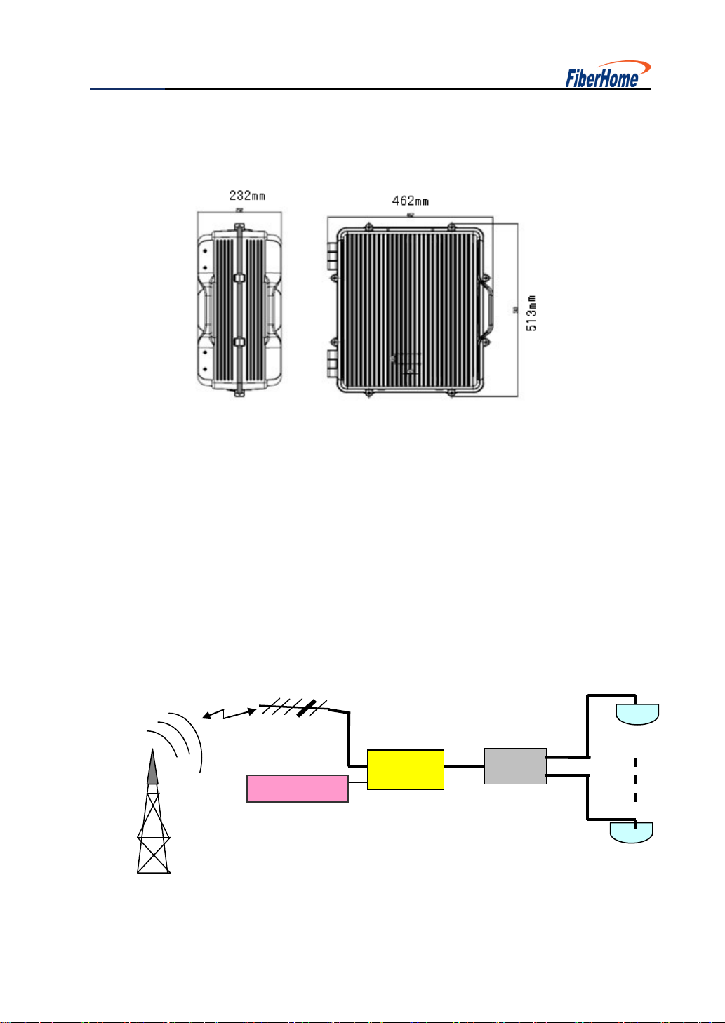
1.4.2 Other Specification
MECHANICAL SPECIFICATION
Dimensions Approx.
513×462×232mm
Weight Approx.
17.4kg
Ingress Protection Class
IP65
ENVIRONMENT SPECIFICATION
Operating Temperature
-25 ~+55℃
Humidity
≤95%
OTHER SPECIFICATION
System Impedance
50Ω
RF Connector
N-type
Power Supply
AC 220V 45 ~ 65Hz
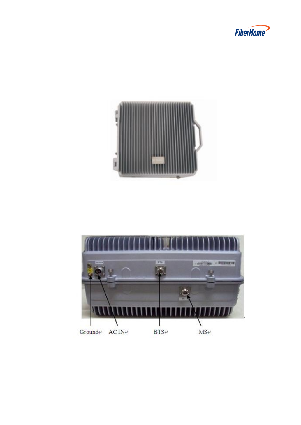
1.5 Interfaces
Antenna interface: N-type connector
Laptop interface: RS232
User Manual
5
1.6 Structure
1.6.1 Figure of Repeater
1.6.2 Figure of Side Panel
User Manual
6
1.6.3 Dimension
2. Applications
Accessing the signal by using a small Yagi antenna or Logarithm period antenna, low
power repeater amplifies the signal and combines the indoor distribution system, which
quickly improve the signal in shadowy or blind zones.
Cable
Repeater
Splitter
CeilingANT
Ceiling ANT
Yagi ANT
Power Switch
User Manual
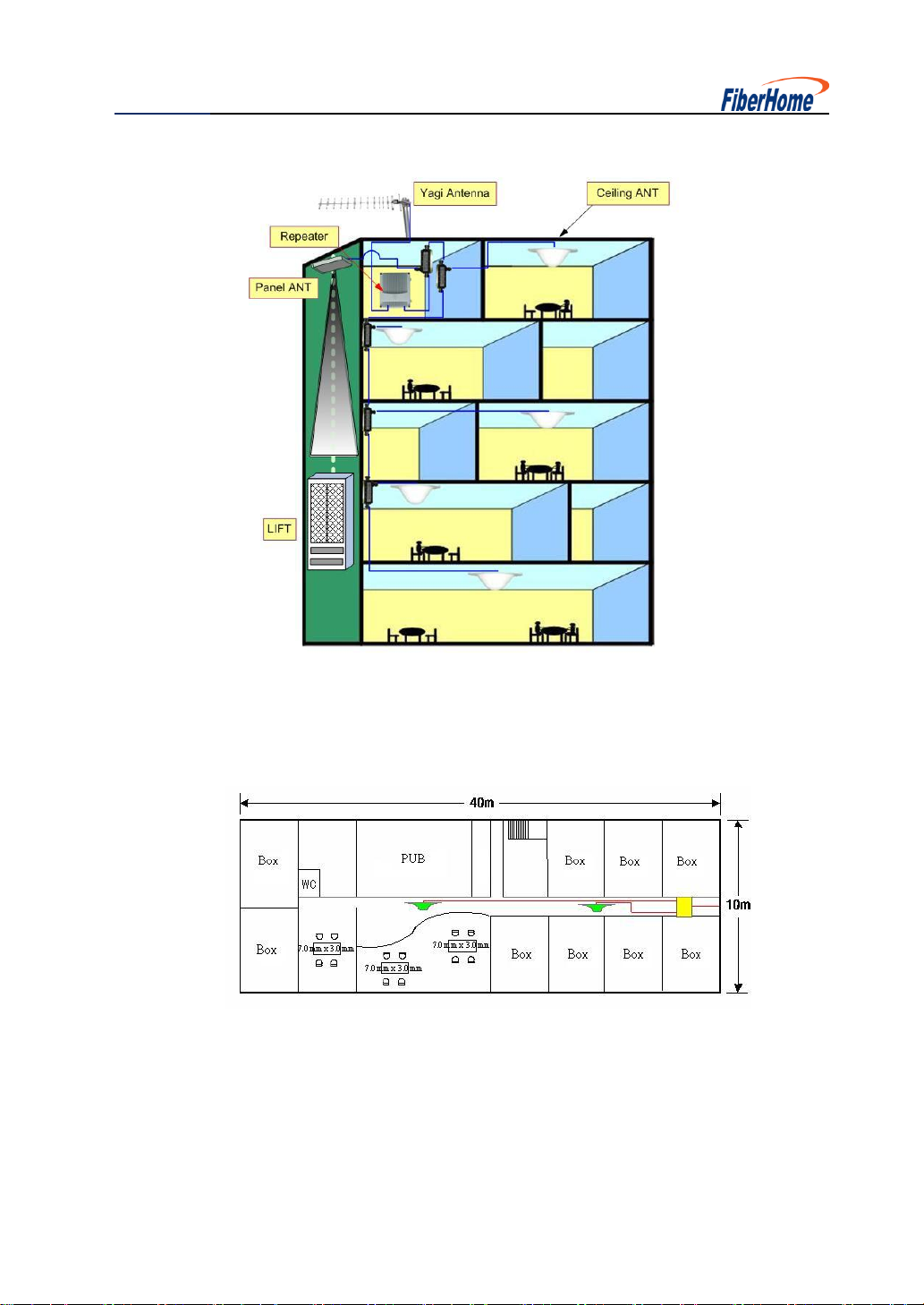
7
Indoor Distribute System
User Manual
8
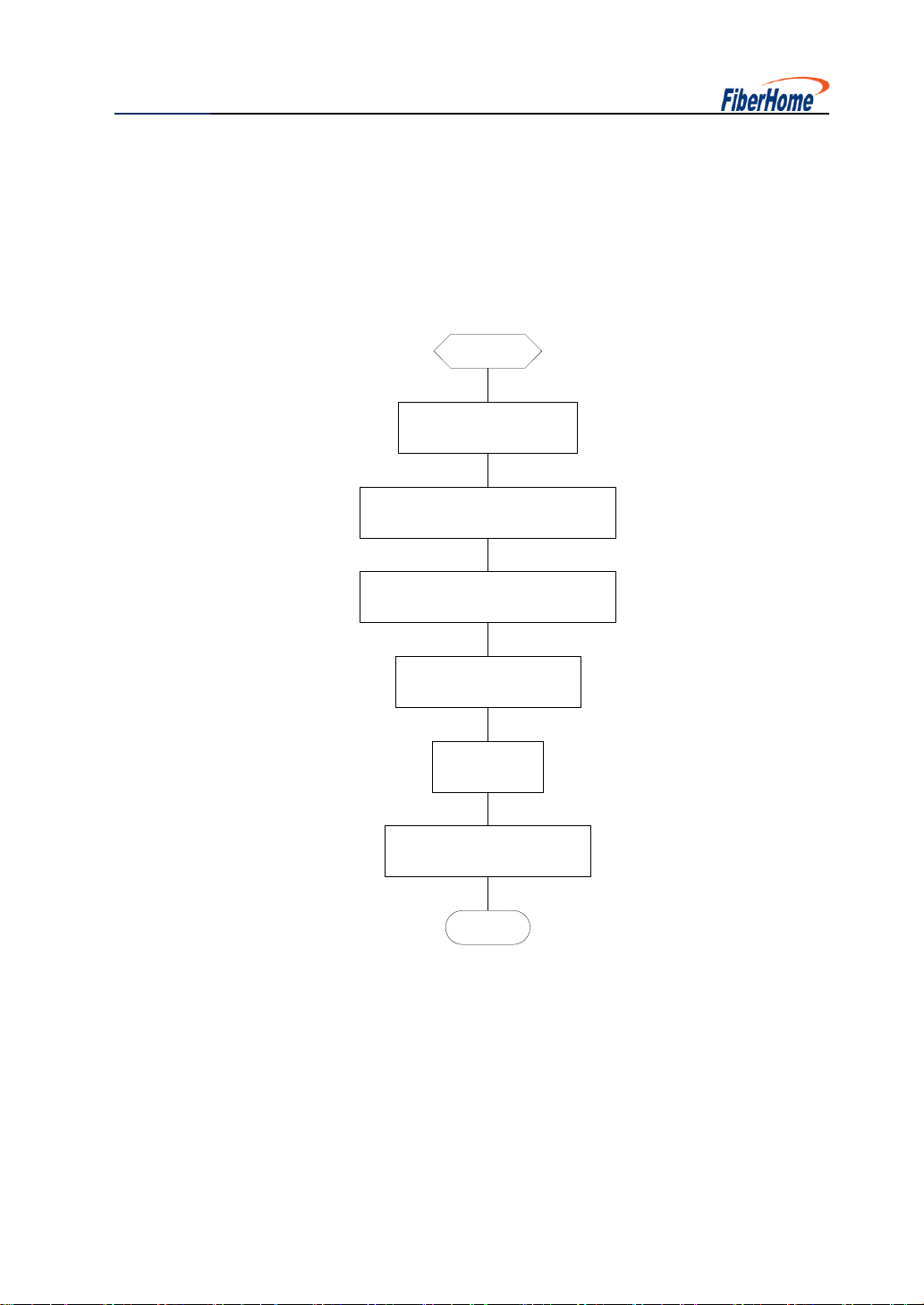
3 Installation
3.1 Installation Flow
The general workflow of the repeater is shown in Fig. 3-1.
Start
End
Project Preparation
Unpacking&goods checking
Antenna&feeder installation
Repeater installation
Grounding
AC power connection
Fig.3-1. the general workflow of the repeater
To ensure safety during the installation, make sure to wear safety belt for
overhead operations and wear safety hats for on-the-ground operations, and
take care never to work in rainstorms.

User Manual
9
3.2 Project Preparations
3.2.1 User’s Cooperation
Technicians will take charge of the equipment installation and the user’s technicians
should provide help if necessary. To ensure the normal running and maintenance of
the equipment, the user’s technicians should proactively work together with engineers
and technicians and get familiar with the installation, structure, cabling, debugging
procedure, etc.
3.2.2 On-site Survey
Before installation, the installation technicians should consult with the project manager
of the user and learn whether the installation site is ready for equipment installation.
Specifically, they should survey such items as the installation site, iron tower or high
pole, surrounding environment (temperature and humidity) and power supply. Where
conditions permit, they should make an on-site survey together with the relevant
persons of the user.
3.2.3 Installation Tools
Installation tools include: electric percussion drill, iron hammer, pulley, rope, safety
belt, safety hat, ladder, screwdriver, hacksaw, knife, pliers, spanner, compass, tape,
tweezers, electric iron, etc.

User Manual
10
3.2.4 Technical Documentation
The installation technicians should keep on hand, and read in advance, such
documents as Project Design Document, Equipment Installation Specifications, and
User Manual for the GZF1900-VH.
3.3 Installation Conditions
3.3.1 Basic Installation Conditions
The repeater is designed to work outdoors under the temperature -25℃~55℃and
relative humidity up to 95%, so it can work in the indoor/outdoor natural environments
in most areas. The following basic conditions should be ready before installation:
1. 220V AC power is available.
2. A grounding bar is available nearby.
3. There are appropriate buildings, iron towers or high poles to mount the donor
antenna and service antenna.
3.3.2 Recommended Environment Requirements
1. The installation height should be such as to facilitate RF cabling, heat radiation,
safety protection and maintenance.
2. Independent and stable 220V AC Power should be provided, which mustn’t be
shared with other large-power communication equipment and electric appliances.
3. The installation building, iron tower or high pole should be provided with lightning
protection facilities and should be strong and stable enough.
4. The antenna backstay or roof should be provided with a pole to help mount the

User Manual
11
antenna. The diameter of the pole may be 50mm ~ 105mm, depending on the
antenna to be mounted. A ladder should also be available to help mount the
antenna. All metal parts should be properly grounded and provided with lightning
protection facilities.
3.4 Equipment Check
3.4.1 Counting the Goods
Check whether the packing box is intact in appearance. If any goods are wrong or
missing or if the outer package is damaged seriously, stop unpacking immediately and
find out the cause, and report to the relevant department.
3.4.2 Unpacking Inspection
Open the packing box if it is intact. Handle with care to avoid damaging anything.
After the packing box is opened, check whether the goods inside match the packing
list and whether the packing list matches the inspection list in the Unpacking
Inspection Report. If any goods are wrong or missing or if the outer package is
damaged seriously, find out the cause, and report to the relevant department.
After unpacking inspection, fill out the Unpacking Inspection Report. Both parties shall
sign the Report, and then the goods shall be handed over to the user. Each party shall
hold one copy of the Unpacking Inspection Report, and the project supervisor should
feed back the “Inspection Conclusion” within seven days to the vendor for
documentation.
User Manual
12
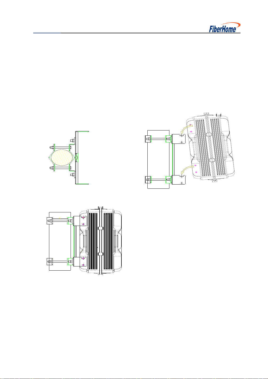
3.5 Installation of the Main Chassis of the Repeater
The repeater is attached with such installation fittings as installation board and fixing
pieces. The chassis of the repeater can be mounted either on the wall or on a high
pole. The bottom of the equipment is usually about 1.2 m above the ground.
Aluminum mould case mounting is shown below.

User Manual
13
4. Site Commissioning
Note: Please excuse us for not giving any further notice about any changes of
operation. FiberHome privileges to the final explanation of LMS.
We take local version software as an example to explain how to configure the
parameters. It is applicable in the windows2000, and windows XP operation system.
4.1 Configure the Software
The following steps are the process of connecting PC or laptop to the repeater on the
site. Be sure the connecting cable is RS232.
4.1.1 Configure the Communication Server
Open the LMS software file, running the LMS firstly, click the icon of LMS with the right
button of the mouse, and then choose open to get access into the LMS.
Then you will see the interface below:

User Manual
14
Step1: Choose the “Serial”which connect with testing equipment, then Click “open
serial”. We need RS232 cable to connect the repeater with the PC or laptop.
Port 2Port 1
1
2
3
4
5
6
7
8
9
1
2
3
4
5
6
7
8
9

User Manual
15
The pin 2 and pin 3 of the RS232 cable are crossing connected, and two pins 5 of the
two tie-ins are connected directly. Pins left are not connected.
Step 2: Click “on-line”to connect with testing equipment
Step 3: Click “save configuration”
Table of contents
Other FiberHome Repeater manuals


