FiberHome GZF850-VL User manual

FiberHome/SM/GZF850-VL
GZF850-VL Repeater
(C27Y02JW01YF)
User Manual
Nov. 2010

i
FiberHome reserves the right to make changes without further notice to any
products herein to improve reliability, function or design. FiberHome does not
assume any liability arising out of the application or use any product or circuit
described herein.
No part of this documentation may be excerpted, reproduced, translated, annotated
or duplicated, in any form or by any means without the prior written permission of
FiberHome Corporation.
All rights reserved.
Copyright © 2010 FiberHome Corporation.

ii
Instruction for your safety
Please be sure to pay attention to all cautions and warnings
before using the system.
Incorrect usage could lead to an electrical shock, damage to
the system or a fire hazard.
■Warning
Do not modify, disassemble or remove the cover. These actions could cause electrical
shock. We shall never be responsible for any problems caused by your reconstruction or
modification.
Do not touch the internal components. They may have high voltage or high temperature.
You may get electrical shock or burnt.
When the system is operating, keep your hands and face away from it. Otherwise, you
may get injured by an accident.
■Caution
Please read catalogue and instruction manual carefully before use.
Use the products within the specified input voltage, temperature and humidity. Use of
products in non-specified condition may damage the product.
Connect the frame ground terminal to the ground terminal of the device for safety. Use
of the products without ground connection may cause an electrical shock.
Do not use the product in the environment with strong electromagnetic field, gas and
conductive substances.

iii
Preface
GZF850-VL Repeater is widely used for constructing a hybrid mobile communications
network. It receives and amplifies forward and reverse Radio Frequency (RF) signal to
extend the coverage of base station. This user manual covers the system frame, technical
specification, operation and maintenance of software of the repeater.

iv
INDEX
1. GENERAL ...........................................................................................................................................1
1.1 SYSTEM FRAME................................................................................................................................1
1.2 PRODUCT FEATURES.........................................................................................................................2
1.3 HARDWARE AND SOFTWARE CONFIGURATION REQUIREMENT..........................................................3
1.3.1 Computer Hardware.............................................................................................................3
1.3.2 Computer Software...............................................................................................................3
1.4 TECHNICAL SPECIFICATION ..............................................................................................................3
1.4.1 Specification of GZF850 –VL.............................................................................................3
1.4.2 Other Specification ...............................................................................................................4
1.5 INTERFACES......................................................................................................................................4
1.6 STRUCTURE ......................................................................................................................................5
1.6.1 Figure of Repeater................................................................................................................5
1.6.2 Figure of Side Panel.............................................................................................................5
1.6.3 Indication Specification........................................................................................................6
1.6.4 Dimension..............................................................................................................................6
2. APPLICATIONS..................................................................................................................................7
3. INSTALLATIONS...............................................................................................................................8
4. SITE COMMISSIONING....................................................................................................................9
4.1 INSTALL THE SOFTWARE .................................................................................................................10
4.1.1 Install the Communication Server ....................................................................................10
4.1.2 Install the Local Version Monitor Software......................................................................12
4.2 CONFIGURE THE SOFTWARE ...........................................................................................................15
4.2.1 Configure the Communication Server..............................................................................15
4.2.2 Configure the Monitor Software........................................................................................17
4.3 INITIAL MONITOR SETTINGS...........................................................................................................18
4.4 MONITOR INTERFACE ILLUSTRATION..............................................................................................22
4.5PRINCIPLE SETTINGS .......................................................................................................................24
4.5.1 Power Limit..........................................................................................................................24
4.5.2 ATT Settings ........................................................................................................................24
4.5.3 On-off Setting ......................................................................................................................25
4.5.4 Frequency Configuration ...................................................................................................26
4.6 EXTEND PARAMETER SETTINGS......................................................................................................27
4.6.1 Repeater Information..........................................................................................................27

User Manual
1
1. General
1.1 System Frame
The following figure shows the system frame of repeater.
DonorANT
Duplex
ServiceANT
LNA
UL ATT
DL ATT
Duplex
PA
PA
LNA
Uplink
Power
Supply
TCXO
Battery
RF signal flow M&C signal flow Antenna
Downlink
GZF850 –VL
(C27Y02JW01YF)

User Manual
2
1.2 Product Features
Excellent RF performance: FiberHome provides wireless repeaters with
state-of-the-art performance such as minimized noise figure, time delay and IMD,
excellent link balance and out-of-band suppression.
Modular design: Modular design is easier for operators to make upgrade and
maintenance.
Monitor and control (M&C): The interior M&C module is the core to control the whole
repeater and implements four functions: detection, control and communication.
Perfect query, statistic and report: It can support query, statistic and report for the
history data including log, repeater data and query data etc.
Reliability: Industrial-level components are used, which can sustain a temperature
range of -25°C ~ +55°C (for outdoor repeater only) so that the product can work
reliably in a wide range of environments; the power supply of the integrated system is
designed with high redundancy to make sure that the power module can work under
normal load in 55°C and start normally in -25°C; the repeater is provided with
multi-level lightning protection devices to ensure reliable lightning protection for the
power supply, antenna and feeder. The lightning protection device of the power supply
is a combination of a gas discharge tube and a piezo-resistor and is designed with
2-level protection, so that it can absorb very high lightning strike energy as well as
remove residual voltage satisfactorily.
User Manual
3
1.3 Hardware and Software Configuration Requirement
1.3.1 Computer Hardware
CPU primary frequency:1.8G or above, 256M memory or above, above 16M
graphic memory, 15" display with pixel of 800×600;
Options: 16-bit sound card, sound box, laser or jet printer.
1.3.2 Computer Software
If installing V5.1.0 (Local version), it is suggested to install Window2000/
XP/Window2003. It is necessary to install DirectX (8.0 or above) for
Window98/ME.
There is no special requirement for configuring communication server.
1.4 Technical Specification
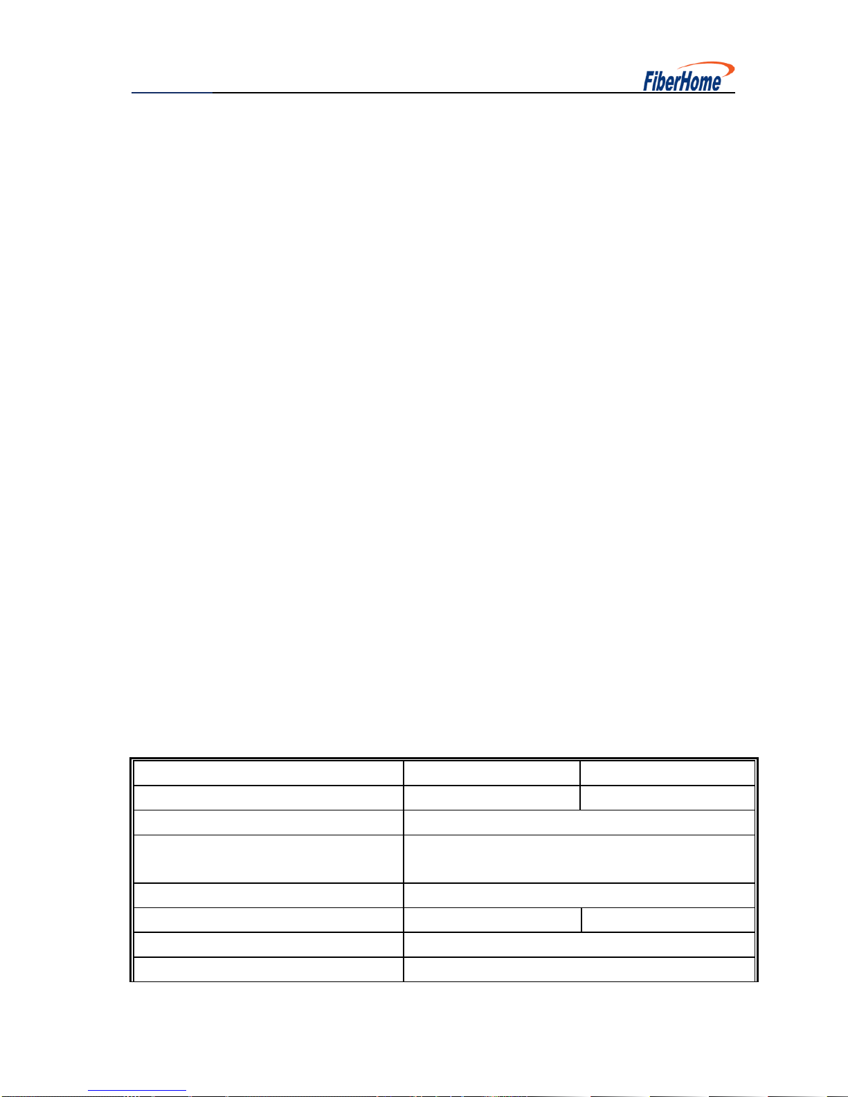
1.4.1 Specification of GZF850 –VL
Technical Specification
Uplink
Downlink
Frequency Band
824 ~ 849MHz
869 ~ 894MHz
Number of Band adjustable Modules
2
Operating Frequency for Each Band
adjustable Module
2-15MHz and 1-6MHz
System Gain
75±2dB
Total Output Power
17±2dBm
27±2dBm
ATT Range in 1dB Step
0~25dB
Noise Figure
≤6dB

User Manual
4
Pass Band Ripple
≤6dB
Group Delay
≤9μs
Automatic Level Control
Within 2dB or shut off
Spurious
Emission(out
of working
band 2.5MHz
9kHz~1GHz/100kHz
≤-36dBm
1GHz~12.75GHz/1M
Hz
≤-30dBm
VSWR
≤1.5
1.4.2 Other Specification
MECHANICAL SPECIFICATION
Dimensions Approx.
420×270×70mm
Weight Approx.
9.0kg
Ingress Protection Class
Indoor use
ENVIRONMENT SPECIFICATION
Operating Temperature
-25 ~+55℃
Humidity
≤95%
OTHER SPECIFICATION
System Impedance
50Ω
RF Connector
N-type
Power Supply
AC 220V 45 ~ 65Hz
1.5 Interfaces
Antenna interface: N-type connector
Laptop interface: RS232
User Manual
5
1.6 Structure
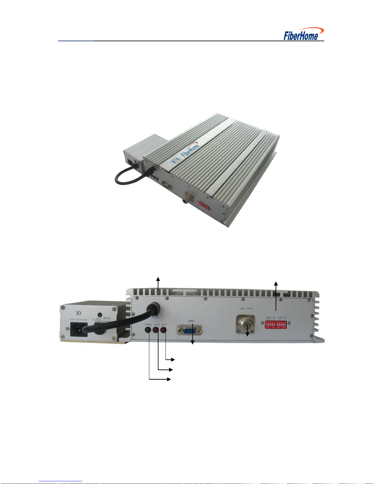
1.6.1 Figure of Repeater
1.6.2 Figure of Side Panel
DC IN
Local interface: RS232
UL/P Status LED
DL/P Status LED
Power Status LED
Donor ANT
ATT

User Manual
6
1.6.3 Indication Specification
DonorANT: to be connected outdoor antenna.
ServiceANT: to be connected indoor antenna.
POWER: when normal working, power supply status is green.
1.6.4 Dimension
W: 270mm
H: 70mm
L: 420mm
70mm
125mm
40mm
m
Service ANT
User Manual
7
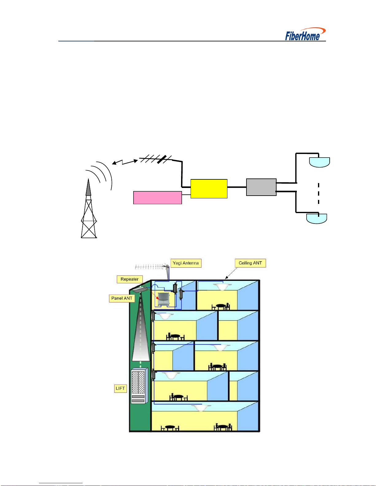
2. Applications
Accessing the signal by using a small Yagi antenna or Logarithm period antenna, low
power repeater amplifies the signal and combines the indoor distribution system,
which quickly improve the signal in shadowy or blind zones.
Cable
Repeater
Splitter
CeilingANT
Ceiling ANT
Yagi ANT
Power Switch

User Manual
8
Indoor Distribute System
3. Installations
Sketch Map
Firstly, select an appropriate position to mount. The signal booster is better to be
mounted close to walls.At the position selected, punch a hole in the wall as shown
in the diagram and aim the bolt at the hole. Then fasten and fix with expansion
bolts.
To be connect the service ANT Port with out door reverse antenna through radio
frequency cable. In general, the reverse antenna is mounted at a higher position.
Yagi antenna and panel antenna may be used. The main lobe of the antenna
radiation is oriented towards the base station and the reverse antenna and base
station antenna should be visible as possible.

User Manual
9
Connect donor ANT Port with the ports of indoor covering system or indoor relay
antenna. In general, the indoor covering system is composed of several splitters,
couplers, expansion amplifiers and antennas and applied as per specific
engineering design for the purpose of satisfying the signal covering demands in
large area or complicated terrain indoor space. In the case of small area indoor
space, the requirements for covering can be satisfied by using single relay
antenna with the option of hanging antenna or ceiling antenna.
Finally, connect the power interface shown as in the diagram to power adapter
and power on the adapter with 220V AC. The signal amplifier installation is thus
completed.
4. Site Commissioning
Note: Please excuse us for not giving any further notice about any changes of
operation. FiberHome privileges to the final explanation of EMS.
Our EMS has two sets of software, one is local version monitor software, and the
other is the SQL version monitor software. We take local version software as an
example to explain how to configure the parameters.
In the local version software has two parts: communication server and monitor
software. It is applicable in the windows2000, and windows XP operation system.
User Manual
10
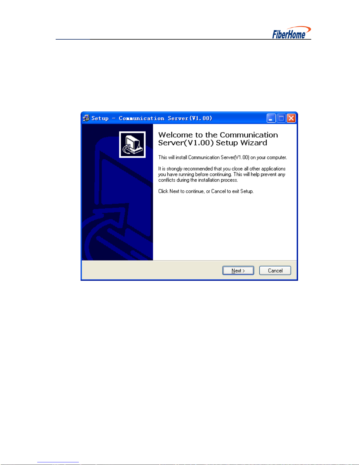
4.1 Install the Software
4.1.1 Install the Communication Server
Set up the communication server as follows:

User Manual
11

User Manual
12
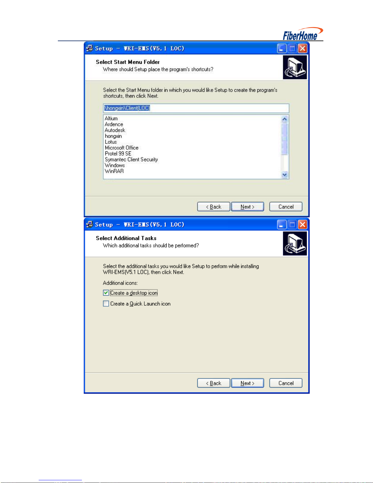
4.1.2 Install the Local Version Monitor Software
User Manual
13

User Manual
14
Click the “Finish”button, the monitor software can be installed successfully.

User Manual
15
4.2 Configure the Software
The following steps are the process of connecting PC or laptop to the repeater on the
site. Be sure the connecting cable is RS232.
4.2.1 Configure the Communication Server
Running the communication server first, click the icon of the communication server
with the right button of the mouse, and then choose configure to get access into the
Communication Server Configuration.
Then you will see the interface below:
Table of contents
Other FiberHome Repeater manuals


