FiberHome AN5121-4GP User manual

An Expert in Optical Communications
User Manual
AN5121-4GP
PON Optical Network
Unit
Version: A
Code: MN000001901
Date: September 2014
FiberHome Telecommunication Technologies Co., Ltd.

Version
Version Description
A Initial version.
are trademarks of FiberHome Telecommunication Technologies Co., Ltd.
(Hereinafter referred to as FiberHome)
All brand names and product names used in this document are used for
identification purposes only and are trademarks or registered trademarks
of their respective holders.
All rights redserved
No part of this document (including the electronic version) may be
reproduced or transmitted in any form or by any means without prior
written permission from FiberHome.
Information in this document is subject to change without notice.

Contents
1 Safety Precautions ............................................................. 1
2 Product Introduction.......................................................... 3
2.1 Product Overview ...........................................................3
2.2 Network Application........................................................6
2.3 Technical Specifications..................................................7
3 Product Appearance........................................................ 10
3.1 Appearance..................................................................10
3.2 Indicator LED Description .............................................13
3.3 Interface Description.....................................................15
3.3.1 Interfaces of the Waterproof Shell .......................15
3.3.2 Interface of the Equipment..................................15
3.3.3 Introduction to the Pole Components ..................17
3.3.4 Introduction to the Cabinet Components .............18
4 Product Installation.......................................................... 19
4.1 Installation Preparation .................................................19
4.2 Plane Mounting Mode...................................................19
4.3 Pole-holding Mounting Mode.........................................20
4.3.1 Installation Flow Chart ........................................20
4.3.2 Pole Mounting Mode...........................................21
4.3.3 Securing the Equipment .....................................24
4.3.4 Connecting Wires and Cables.............................26
4.4 Wall Mounting Mode .....................................................37
4.4.1 Installation Flow Chart ........................................37

4.4.2 Wall Mounting Mode ...........................................38
4.4.3 Securing the Equipment .....................................41
4.4.4 Connecting Wires and Cables.............................42
4.5 Cabinet Mounting Mode................................................42
4.5.1 Installation Flow Chart ........................................42
4.5.2 Installing the Mounting Ears................................43
4.5.3 Cabinet Mounting Mode......................................44
4.5.4 Connecting Wires and Cables.............................46
4.6 Post-installation Inspection ...........................................47
5 FAQ ...................................................................................... 49

1 Safety Precautions
1 Safety Precautions
Large-power laser is dangerous to human body, especially
to eyes. Do not face the pigtail fiber of the optical
transmitter or the end of the fiber cable connector to eyes.
Power sockets with too heavy load or damaged cables and
connectors may cause electric shock or fire. Regularly
check related electric cables. If any electric cable is
damaged on appearance, replace the electric cable
immediately.
When inserting the power connector of the device into an
external power socket, make sure that the external power
socket is close enough to the device, for easy operation.
If the power cable of the device is straightly connected to
an external power supply, switch off the external power
supply before connecting the power cable. Hot-line
operation is prohibited.
Do not fix the product on an unstable support.
Do not use the device when the grounding cable is
damaged or no proper grounding cable is used. Perform
regular electric inspection. If the grounding cable is
damaged, replace it immediately.
1

1 Safety Precautions
Install the silicon rubber waterproof band into the recess on
the lower cover of the device case to ensure water
proofing.
2

2 Product Introduction
2 Product Introduction
The following introduces the functions, network applications and
technical specifications of the AN5121-4GP.
2.1 Product Overview
The AN5121-4GP is a GPON FTTB / FTTV type remote terminal
specially developed for the network access at the outdoor
environment, the video monitoring, the Wi-Fi hot spot deployment,
etc. It has the data service access and Power over Ethernet (PoE)
functions and can form a gigabit GPON system with the FiberHome
GPON station central office devices.
The AN5121-4GP has one GPON uplink port, whose uplink
transmission distance can reach 20 km, so as to deploy the
equipment conveniently. Its four GE interfaces can act as the data
and power supply interfaces at the same time, so as to provide the
power supply and data services for the downlink equipment.
The PoE function for the AN5121-4GP is to provide the power
supply for the remote equipment via the network cable directly. This
can lower the deployment costs and difficulty of some types of
remote equipment sets.
It can be used together with the assorted protection case. This
device features lightning protection, water proofing, power surge
prevention, high and low temperature resistance, oxidation
resistance, acid, base and corrosion resistance, and high reliability.
It can be installed and operates under unfavorable outdoor
conditions.
3

2 Product Introduction
Function
The AN5121-4GP supports the following functions:
uBasic PON functions:
4Uses the GPON connection in the uplink direction, meeting
the ITU-T G.984 standard.
4Supports multiple authentication modes, including the
physical ID authentication, the password authentication,
and the logical SN authentication.
4Supports the downlink data encryption through the
AES128 algorithm.
uBasic Ethernet functions:
4Supports the statistics about the Ethernet interface
performance.
4Supports the Ethernet interface working mode selection.
The Ethernet interface can work under the 10 / 100 / 1000
Mbit/s, full-duplex / half-duplex status in the auto
negotiation or the forced mode.
4Supports the LAN-port-based rate control function and the
MAC address limit function.
uVLAN related functions:
4Supports the 802.1P and 802.1Q VLAN protocols.
4Supports VLAN stacking and selective QinQ.
4Supports the VLAN transparent transmission and VLAN
translation in the 1:1 mode.
4Supports VLAN tags carried by the multicast packets.
4Supports the rate limiting function based on VLAN.
uMulticast related functions:
4Supports the multicast protocols such as the IGMP
Snooping and the IGMP V2 / V3.
4Supports the IPv6 multicast protocols such as the MLD
Snooping and the MLD V1 / V2.
4

2 Product Introduction
uQoS and ACL related functions:
4Supports the ACL function, which means traffic matching
according to the ACL rules.
4Provides powerful QoS capabilities and supports three
scheduling modes: SP, WRR and SP + WRR.
4Supports the queue mapping. The system can map to the
corresponding priority queue according to the 802.1P
priority and the DSCP priority.
4Supports the flow rate control based on the flow
classification rule and the re-marking of priority.
4Supports bandwidth rate control based on the ONU, and
guarantees the services with higher priorities.
uAccess control functions:
4Supports the DHCP line label function.
4Supports the PPPoE+ function, used to identify users
exactly.
4Supports the DHCPv6 protocol (without the status
information) and the PPPoEv6 protocol.
uEquipment management and maintenance functions:
4Supports the local WEB network management function.
The operators can log in via the user LAN port to view the
information of the AN5121-4GP and modify the logical SN
and password of the ONU.
4Supports managing the ONU remotely in the Telnet mode,
and users can view the ONU status information and print
the debug information.
4Supports the log management and status viewing functions,
enabling users to obtain the equipment debugging
information.
4Supports alarm reporting and filtering functions.
uSecurity related functions:
5

2 Product Introduction
4Supports limiting the quantity of MAC addresses at a
certain port.
4Supports the broadcast storm restriction function for the
user port and the uplink port.
4Supports protection against various network attacks
(including ARP attack, ICMP attack, DOS attack, and
BPDU attack).
uLayer-3 related functions:
4Supports the NAT address translation function.
4Supports the IPv4 / IPv6 double stacking.
uPoE functions:
4Supports the IEEE 802.3 AF / AT standard, and the
maximum power of the integrated equipment is 120 W.
4Supports the automatic / manual feed mode.
4Supports querying the feed status of a port.
Product Model
AN5121-4GP with four GE interfaces.
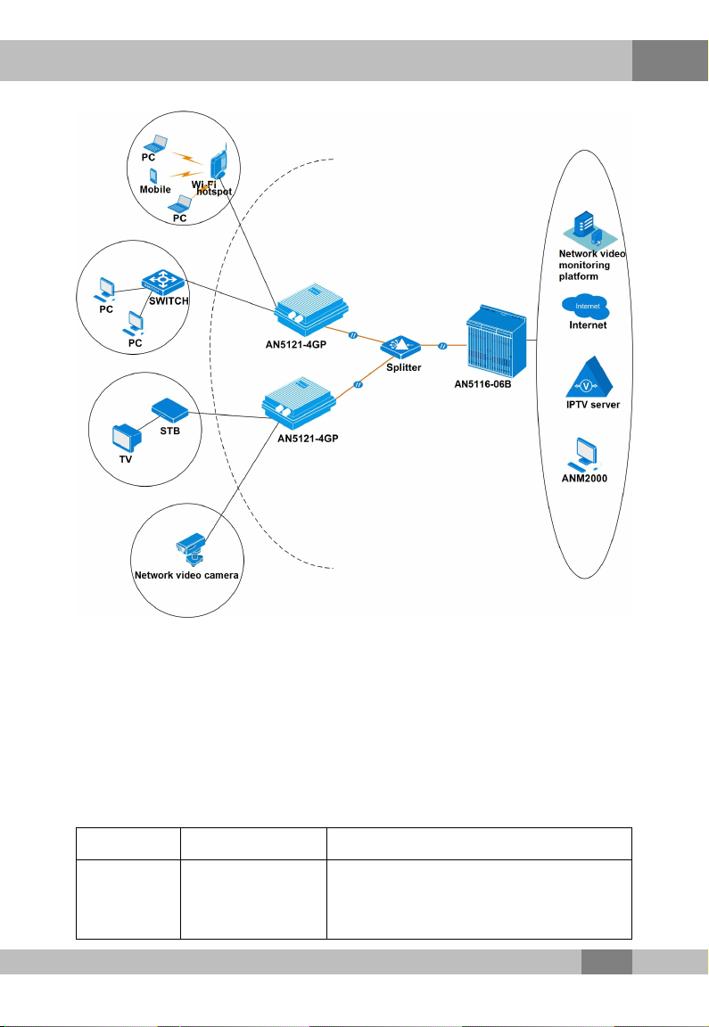
2.2 Network Application
The AN5121-4GP is mainly used in the FTTB / FTTV type access
scenarios, providing the power supply for some equipment sets and
the access of the data services for users.
The AN5121-4GP is characterized by its adaptability to multiple
outdoor installation scenarios. Therefore, it can serve as the network
access equipment in the field or at public locations.
The network of the equipment in the common application scenario is
shown in Figure 2.1.
6
2 Product Introduction
Figure 2.1 The AN5121-4GP Application Network
2.3 Technical Specifications
The technical specifications of the AN5121-4GP are listed in Table
2.1.
Table 2.1 The AN5121-4GP Technical Specifications
Type Item Description
Service
parameters VLAN
Supports the IEEE 802.1Q / 802.1P
VLANs and VLAN-based selective QinQ.
Supports 4095 VLANs at most.
7

2 Product Introduction
Table 2.1 The AN5121-4GP Technical Specifications (Continued)
Type Item Description
MAC address The capacity of the system MAC address
table is 1K.
Layer 2 line rate
forwarding All ports support line rate forwarding.
QoS
Supports eight priority queues at most.
Supports the SP, WRR, and SP + WRR
scheduling modes. The SP scheduling
mode is used by default.
Network
side
interface
GPON interface One GPON interface is available, which
meets the ITU-T G.984 standard.
User side
interface GE interface
Four GE interfaces are available, whose
type is RJ-45. They support 10 / 100 /
1000 Mbit/s full-duplex / half-duplex
adaptation.
Network cables are category-5
waterproof cables.
Supports the PoE function, based on the
IEEE 802.3AF / AT standard. For the
PoE, the maximum output power of the
integrated equipment is 120 (4×30) W,
and the maximum output power of a
single interface is 30 W.
Mechanical
parameters
Waterproof shell
size
80mm × 280mm × 340mm (height x
width x depth).
Equipment size 45 mm × 240 mm × 150 mm (H × W × D)
Weight <1.5kg
Power
supply
parameters
AC AC 220 V
8

2 Product Introduction
Table 2.1 The AN5121-4GP Technical Specifications (Continued)
Type Item Description
Power
consump-
tion
parameters
Full load <130W
Empty load <10W
Environ-
ment
parameters
Operating
temperature -30℃to 55℃
Storage
temperature -55℃to 125℃
Environmental
humidity 0% to 80% (no condensation).
9
3 Product Appearance
3 Product Appearance
3.1 Appearance
The following introduces the appearance of the AN5121-4GP and
the waterproof shell for it.
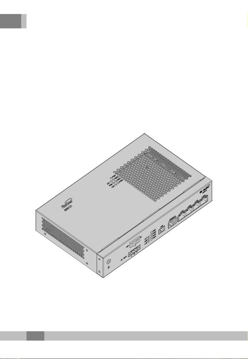
The AN5121-4GP
The overall appearance of the AN5121-4GP is shown in Figure 3.1.
Figure 3.1 The Appearance of the AN5121-4GP
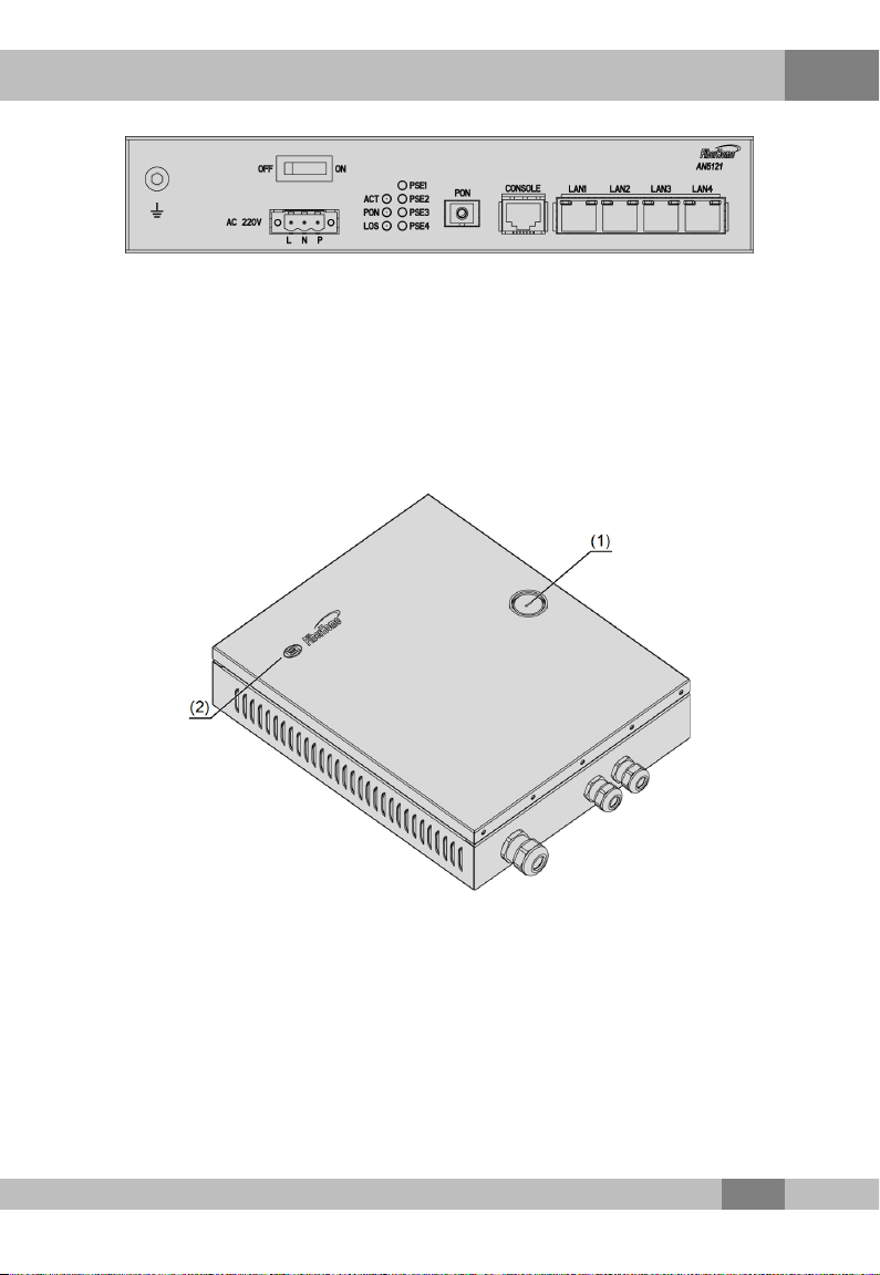
The panel of the AN5121-4GP is shown in Figure 3.2.
10
3 Product Appearance
Figure 3.2 The AN5121-4GP Panel
Waterproof Shell
The waterproof shell can be used together with the AN5121-4GP. Its
top internal side is equipped with the waterproof bumper case, which
can prevent the rain from entering the shell via the gaps. The
appearance of the waterproof shell is shown in Figure 3.3.
(1) Lock (2) LOGO (can be customized)
Figure 3.3 Appearance of the Waterproof Shell
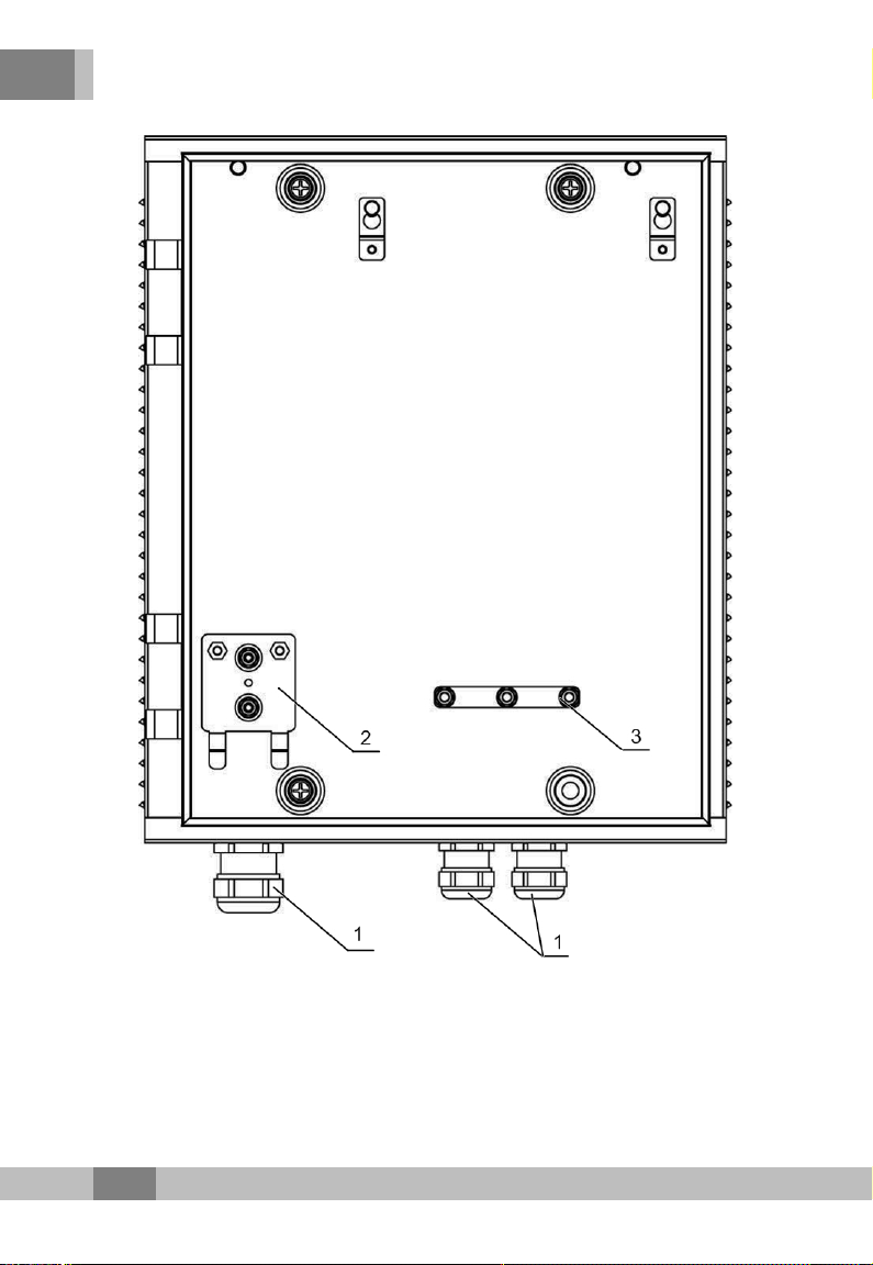
The internal structure of the waterproof shell is shown in Figure 3.4.
11
3 Product Appearance
(1) Wiring hole
(optional)
(2) Earth ground
component (optional)
(3) Cable fixing
component (optional)
Figure 3.4 Internal Structure of the Waterproof Shell
12

3 Product Appearance
The main components inside the waterproof shell are described in
Table 3.1.
Table 3.1 The Main Components inside the Waterproof Shell
Component Name Component Description Component
Quantity
Wiring hole (optional) For leading the wires and cables into
the equipment from the external. 3
Earth ground
component (optional)
Used to provide the earth ground
point for the equipment earth ground
cable and the optical cable reinforced
core inside the shell.
1
Cable fixing
component (optional)
For securing multiple network cables
from the AN5121-4GP to the external. 1
3.2 Indicator LED Description
The AN5121-4GP has multiple types of indicator LEDs on it. Except
for the four indicator LEDs (ACT, PSE, PON, and LOS), the link
status and duplex status indicator LEDs are located beside each
LAN port. The description on each indicator LED is shown in Table
3.2.
Table 3.2 Description on Indicator LEDs of the AN5121-4GP
Silk-
screen
Name
Meaning Color Status Indicator LED Description
ACT
Working
status
indicator
LED
Green
Blinking The logical link has been set
up.
OFF The logical link has not been
set up.
13

3 Product Appearance
Table 3.2 Description on Indicator LEDs of the AN5121-4GP (Continued)
Silk-
screen
Name
Meaning Color Status Indicator LED Description
LOS
Optical
signal status
indicator
LED
Red
ON The Rx optical power of the
PON port is too low.
OFF The Rx optical power of the
PON port is normal.
PON
PON status
indicator
LED
Green
ON The AN5121-4GP is
registered.
OFF The AN5121-4GP is not
registered
LAN
Link status
indicator
LED (left)
Orange
ON
A certain equipment set is
connected to the LAN port,
without data transmission.
Blinking
A certain equipment set is
connected to the LAN port,
with data transmission.
OFF No equipment set is
connected to the LAN port.
Duplex
status
indicator
LED (right)
Green
ON The port operates in the full-
duplex mode.
OFF The port operates in the half-
duplex mode.
PSE
Power
supply status
indicator
LED
Green
ON
The PSE equipment has
been connected to the
interface and is receiving the
power supply.
OFF
The PSE equipment is not
connected to the interface
and is not receiving the
power supply.
14
3 Product Appearance
3.3 Interface Description
3.3.1 Interfaces of the Waterproof Shell
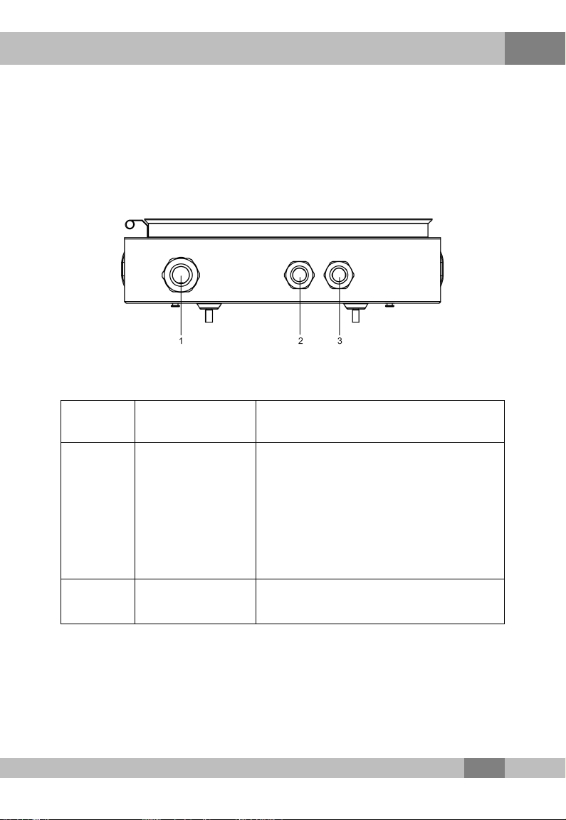
The interfaces on the waterproof shell are shown in Figure 3.5.
Figure 3.5 Interface of the Waterproof Shell
Table 3.3 Interfaces on the Waterproof Shell
Serial
Number Interface Description
(1)
Wiring hole for the
earth ground
cable,
Wiring hole for the
power cable,
Wiring hole for the
optical cable.
The earth ground cable, the power cable
and the optical cable are led into the
waterproof shell through this interface.
(2), (3) Network cable
wiring hole
The network cable is led in or out of the
waterproof shell through these interfaces.
3.3.2 Interface of the Equipment
The AN5121-4GP's interfaces are all located on the front panel, as
shown in Figure 3.6.
15

3 Product Appearance
Figure 3.6 The AN5121-4GP Panel
(1) Earth ground cable
interface (2) Power switch (3) AC power interface
(4) GPON interface (5) Console interface (6) Ethernet / PoE
interface
See for detailed introduction to each interface.
Table 3.4 Introduction to the Equipment Interfaces
Interface Description
Earth ground
cable interface Used for the earth grounding of the equipment.
Power switch Used to switch on or off the AN5121-4GP.
AC power
interface
Used to induct the 220 V AC power supply from the
external.
GPON interface The uplink PON interface, complying with the ITU-T G.
984 standard.
Console interface The debugging serial port, used to debug the AN5121-
4GP in the local connection mode.
Ethernet / PoE
interface
Four GE interfaces totally, used for the PoE feed or
accessing the downlink equipment via the network
cable.
16
Table of contents
Popular Switch manuals by other brands

GE Zenith Controls
GE Zenith Controls ZTX Operation and maintenance manual

Contemporary Controls
Contemporary Controls CTRLink Skorpion Series installation guide

Process Technology
Process Technology DLC16 manual

IBM
IBM RackSwitch G8264CS installation guide

ORiNG
ORiNG IBS-102FX Quick installation guide

MaxLux
MaxLux МХ0096 quick start guide


