FIC FIPO 10 User manual

Termoregolatore
Thermoregulator
FIPO 10
v.1
Manuale Tecnico
Technical manual
Redazione a cura dell’Ufficio Tecnico della FIC s.p.a.
Le specifiche tecniche sono passibili di cambiamenti senza preavviso, proprietà riservata protetta
a norma di legge.
Drawn up by Technical Office of FIC s.p.a.
Technical specifications may be changed without notice. All rights reserved.
FIC
S.p.a.
Via Trivulzia 54 23020 Mese (SO) ITALY
Tel. +39 0343 41051 Fax +39 0343 41304
Internet www.fic.com
E-mail: fic@fic.com


Indice
Index
1 Caratteristiche............................................................................................................................................1
Propeties .................................................................................................................................................7
2 Quadro di controllo.....................................................................................................................................1
Control panel..............................................................................................................................................7
3 Segnalazioni..............................................................................................................................................2
Indications .................................................................................................................................................7
4 Messaggi sul visore....................................................................................................................................2
Display message........................................................................................................................................8
4.1 Temperatura.............................................................................................................................2
Temperature.............................................................................................................................8
4.2 Compressore............................................................................................................................2
Compressor..............................................................................................................................8
4.3 Agitatori....................................................................................................................................2
Agitators...................................................................................................................................8
4.4 Pompa1....................................................................................................................................3
Pump1......................................................................................................................................8
4.5 Pompa2....................................................................................................................................3
Pump2......................................................................................................................................8
4.6 Ciclo di funzionamento..............................................................................................................3
Running cicle............................................................................................................................9
5 Programmazione cost.................................................................................................................................4
Cost programming....................................................................................................................................10
6 Bootstrap o reimpostazione dati..................................................................................................................5
Bootstrap or data resetting........................................................................................................................10
7 Programmi di funzionamento......................................................................................................................5
Running charts.........................................................................................................................................11
8 Ricerca guasti............................................................................................................................................6
Trouble shooting guide.............................................................................................................................11
9 Schema di allacciamento............................................................................................................................6
Wiring diagram.........................................................................................................................................12


FIPO10 V.1 – Fic S.p.a. Via Trivulzia 54, 23020 Mese (SO) 1
Termoregolatore FIPO 10
1. Caratteristiche
Il termoregolatore FIPO10 è un microcomputer dell’ultima generazione con memoria non volatile, permette cioè la
ritenuta dei dati impostati senza l’ausilio di unità tampone esterne ed è abilitato per il comando ed il controllo di un
compressore e di due elettropompe (se previste) secondo un programma settimanale da stabilire a cura del Cliente.
Sul frontale, oltre ai ben contrassegnati comandi per ogni funzione, trova spazio un display ad alta luminosità che
visualizza le varie grandezze rappresentate; una serie di lampadini indicherà progressivamente le funzioni che si
staranno svolgendo.
Il controller permette la segnalazione delle anomalie presenti nell'impianto, prevedendo un'uscita supplementare alla
quale l’Utilizzatore può collegare un segnalatore acustico e/o luminoso.
Tutto ciò è stato programmato nell’ottica di garantire all’Utente la MASSIMA SICUREZZA con la MAGGIORE
SEMPLICITA’ d’uso.
E’ bene inoltre ricordare che FIPO-10 racchiude in sè tutte le funzioni necessarie all’utilizzo del refrigeratore di acqua ad
espansione diretta.
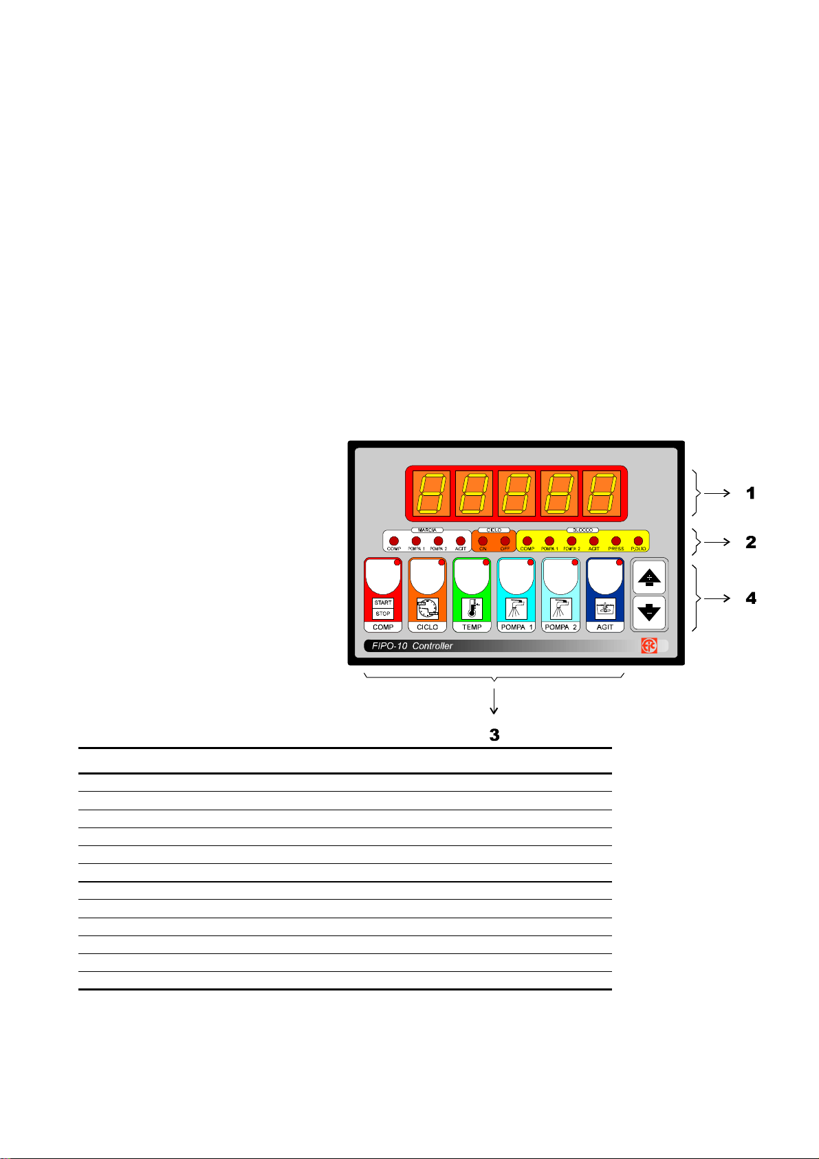
2. Quadro di controllo
Il frontale dello strumento è composto:
1 - da un display di cinque cifre ad alta
luminosità che visualizza sia le
grandezze rappresentate che le
variabili da programmare;
2 - dai lampadini di segnalazione che
indicano gli azionamenti, in
particolare:
- la marcia (visore di colore bianco);
- la ciclo (visore di colore rosso);
- la blocco (visore di colore giallo);
3 - dai tasti per l’attivazione dei
programmi;
4 - dal tasto per la programmazione.
2
3. Segnalazioni
Lampadino Operazione Contatti Relè
COMP Compressore On 3 - 4 1
POMPA 1 Pompa 1 ON 5 - 6 2
POMPA 2 Pompa 2 ON 7 - 8 3
AGIT Agitatori ON 9 - 10 4
CICLO ON Ciclo tempo ON
CICLO OFF Ciclo tempo OFF
BL. COMP Blocco compressore
BL. POMPA 1 Blocco pompa 1
BL. POMPA 2 Blocco pompa 2
BL. AGIT Blocco agitatori
PRESS Blocco pressione gas
P. OLIO Blocco pressione olio
Lampadini tasto POMPA 1 e POMPA 2 lampeggianti per la chiusura del consenso esterno.
4. Messaggi sul visore
- ALL.tE lampeggiante per intervento allarme temperatura.
- -oFF- per intervento stato di OFF (periodo giornaliero).
- StOP a compressore spento.
4.1. Temperatura
Premendo TEMP (lampadino del tasto lampeggiante) viene visualizzato il messaggio t.SET in alternanza
al valore di temperatura impostata; agendo sui tasti + e- è possibile variare la temperatura di lavoro
desiderata.
Premere TEMP per la conferma.
4.2. Compressore
Premere COMP per avviare, se spento, il compressore (lampadino tasto acceso).
Sul visore comparirà la temperatura rilevata dalla sonda; se il valore di temperatura indicato è maggiore di
quello impostato TEMP il compressore partirà. In ogni modo la macchina non partirà se il Programma Ciclo
è in OFF (lampadino CICLO OFF lampeggiante, vedi tasto CICLO).
Premere COMP per spegnere, se accesa, la macchina (lampadino tasto lampeggiante).
Sul visore comparirà il messaggio StOP.
Durante il funzionamento del compressore partono gli agitatori, a compressore fermo si fermano anche gli
agitatori.
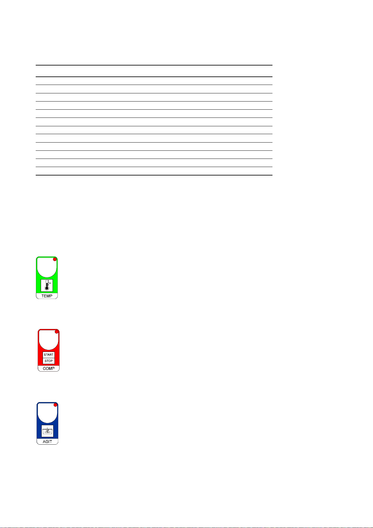
4.3. Agitatori
Premere AGIT per inserire gli agitatori; l'accensione degli agitatori è visualizzata dal lampadino AGIT.
Gli agitatori si spegneranno alla prima fermata del compressore, e ripartiranno assieme al compressore.
Con una delle due pompe accese gli agitatori funzionano.

FIPO10 V.1 – Fic S.p.a. Via Trivulzia 54, 23020 Mese (SO) 3
4.4. Pompa 1
Premere POMPA 1 per accendere la pompa 1; l'accensione della pompa è visualizzata dal lampadino
POMPA 1.
L'accensione della pompa fa partire anche gli agitatori, che alla prima partenza del compressore si
agganciano al funzionamento del compressore.
Durante la fase di CICLO OFF (programmazione a tempo) e alla ripartenza (CICLO ON) lo stato delle
pompe è quello programmato nelle COSt nella funzione P.on.
L'accensione della POMPA 1 può essere effettuato anche da contatto esterno (vedi schema di
allacciamento).
In queste condizioni il lampadino del tasto POMPA 1 lampeggia.
Nel caso di contrasto (con il tasto POMPA si vuole spegnere, con il contatto esterno accendere) comanda
il contatto esterno.
4.5. Pompa 2
Premere POMPA 2 per accendere la pompa 2; l'accensione della pompa è visualizzata dal lampadino
POMPA 2. L'accensione della pompa fa partire anche gli agitatori, che alla prima partenza del compressore
si agganciano al funzionamento del compressore. Durante la fase di CICLO OFF (programmazione a
tempo) e alla ripartenza (CICLO ON) lo stato delle pompe è quello programmato nelle COSt nella funzione
P.on.
L'accensione della POMPA 2 può essere effettuato anche da contatto esterno (vedi schema di
allacciamento).
In queste condizioni il lampadino del tasto POMPA 2 lampeggia. Nel caso di contrasto (con il tasto
POMPA si vuole spegnere, con il contatto esterno accendere) comanda il contatto esterno.
4.6. Ciclo di funzionamento
Prima di provvedere alla programmazione del ciclo di lavoro bisogna mettere a punto l'orologio nel seguente modo:
premere il tasto CICLO per più di 4 secondi per entrare nella programmazione dell'orario; sul visore
comparirà l'orario (hh.mm), agire sui tasti +o - per variarlo, premere CICLO a conferma.
A questo punto sul visore comparirà il giorno della settimana ( d= ), agire sui tasti + o -per variarlo,
premere CICLO a conferma. Dopodichè premere CICLO per programmare i periodi di funzionamento
settimanale. Sul visore comparirà il messaggio -SI- ad indicare che la programmazione è inserita (se si
vuole disinserire la funzione a tempo agire sul tasto -e far comparire sul visore il messaggio -no-; a questo
punto premendo CICLO si esce dalla programmazione e la funzione tempo non condiziona più il
funzionamento della macchina; questa condizione è visualizzata dallo spegnimento di entrambe i lampadini
CICLO).
Se invece si vuole continuare nella programmazione della funzione tempo (messaggio -Si- sul visore)
premere CICLO; sul visore comparirà il messaggio dAy.1 ad indicare la programmazione del primo giorno
della settimana. Premendo il tasto CICLO a conferma, sul visore comprarià il messaggio -On- in
alternanza al valore impostato di ora e minuti di partenza della macchina nel giorno 1. Agire sui tasti + o -
per variarlo, premere CICLO a conferma.
Alla fine della programmazione del dAy.7 (ultimo giorno della settimana) il programma si riporta in
visualizzazione della temperatura della zona programmata.
Per uscire in ogni istante dalla programmazione premere TEMP.
Al messaggio dAy indicato sul display è possibile premendo i tasti +o - far avanzare o retrocedere i
giorni della settimana.
ATTENZIONE !
Se un giorno è di continuo ON programmare -On- = 0.00 e -oFF- = 23.59.
Se si usa la funzione CICLO ricordarsi di inserire l'ora esatta ed il giorno della settimana.
Ovviamente questa operazione è da eseguire solo alla prima accensione, oppure al cambio dell'ora
legale.

4
Manuale tecnico termoregolatore
5. Programmazione cost (Constanti di impianto)
Premere contemporaneamente + / - e COMP per più di un secondo, sul visore comparirà il messaggio C.O.S.t. .
Premere AGIT fino a portarsi sul messaggio della variabile interessata (vedi tabella sottoriportata), sul visore comparirà il
valore impostato di tale variabile, in alternanza al messaggio.
Agire su + o -per impostare un nuovo valore, premere AGIT a conferma. A questo punto comparirà la varibile
successiva in alternanza al valore impostato.
Agire come precedentemente spiegato per procedere nella programmazione, premere AGIT per più di due secondi per
uscire in ogni istante dalla programmazione e ritornare in Funzionamento Normale.
Messaggio Valore Descrizione Note
diF.C 1.0° °C differenziale compressore 1 A
rEL.A 2.0° °C temperatura allarme relativa al °C Se t. B
t.ALL 0' Minuti tempo ritardo allarme temperatura da ON Compress. B
rEL.2 0.0° °C set compressore 2 riferito al t.Set. A
diF.2 1.0° °C differenziale compressore 2 A
t.Con 10” Secondi ritardo inserzione compressore 2 A
t.on 0' Minuti tempo funzionamento CICLO AGITATORI (0=escluso) C
t.oF 0' Minuti tempo attesa CICLO AGITATORI (0=escluso) C
rit.C 10" Secondi tempo ritardo compressore al power on D
P.on =1 Stato delle pompe all'ON CICLO E
Ad.tE 0,0° °C correzione temperatura sonda (+ o -) F
Note:
A- Il (vedi diagramma 11.3)
B- Il valore impostato rEL.A (es. +2 °C) si somma al valore di t.SEt (es. +4 °C). Se i +6 °C risultanti
(rEL.A+t.SEt) non vengono raggiunti dopo il tempo t.ALL impostato il sistema prevede l'intervento dell'allarme di
temperatura segnalato dal messaggio ALL.tE lampeggiante sul visore.
Con impostato t.ALL = 0' l'allarme è escluso.
C- Gli agitatori partono assieme al compressore e si fermano allo stop del compressore, a questo punto si inserice il
funzionamento ciclico in on e in off.
Con impostato t.on = 0' oppure t.oF = 0' il ciclo a tempo degli agitatori non viene inserito.
D- Alla partenza "on" (se richiesta) il compressore si avvia con tempo di ritardo impostato. Durante questo tempo il
lampadino COMP lampeggia.
E- P.on = 1 : in CICLO OFF si spegne tutto, anche le pompe (se inserite); alla ripartenza (CICLO ON) rimangono
spente (si possono ovviamente riaccendere con il tasto POMPA1 e POMPA 2 oppure da contatto esterno).
P.on = 2 : in CICLO OFF si spegne tutto, anche le pompe (se inserite); alla ripartenza (CICLO ON) le pompe
ritornano nello stato inserito prima dello spegnimento (CICLO OFF).
F- E' possibile correggere la lettura della sonda temperatura inserendo una correzione positiva (tasto +) o negativa
(tasto -).

FIPO10 V.1 – Fic S.p.a. Via Trivulzia 54, 23020 Mese (SO) 5
6. Bootstrap o reimpostazione dati
Questo processore è preprogrammato.
Per ritornare in qualsiasi istante a queste preimpostazioni procedere nel seguente modo:
- premere contemporaneamente + / - e AGIT per più di un secondo, sul visore comparià il messaggio boot
(a questo punto lasciare il tasto AGIT);
dopo qualche istante il processore tornerà in Funzionamento Normale, con inserito i seguenti parametri standard
programmati in fabbrica:
t.SEt = 2.0°C
stato StoP
dAY 1 = -on- = 8.00 -oFF- =18.0
ciclo -Si-
L'utente dovrà riprogrammare gli eventuali valori impostati, se diversi dallo standard.
Per facilitare l'operatore riportiamo una tabella, dove nella colonna A sono indicati i valori standard, mentre nella colonna
B lo spazio per le eventuali modifiche.
Messaggio Colonna A Colonna B
t.SEt +2,0 °C
diF.1 1.0 °C
rEL.A 2.0°C
t.ALL 0’
rEL.2 0.0 °C
diF.2 1.0 °C
t.Con 10”
t.On 0’
t.OF 0’
rit.C 10”
P.on =1
Ad.tE 0.0°
CICLO SI
-on- -oFF- -on- -oFF-
dAY 1 8.00 18.00
dAY 2
dAY 3
dAY 4
dAY 5
dAY 6
dAY 7
7. Programmi di funzionamento
ALLARME
ON ALLARME TEMPERATURA :
in azine dopo il tempo t.ALL dalla
partenza del Compressore
Escluso con t.ALL=0
0.2°
OFF
ALLARME
TEMPERATURA rEL.A
rEL.2
COMP 2 COMPRESSORE 2
Solo in fase di START COMP
Condizionato da t.Con (vedi COSt).
diF.2
OFF
COMPRESSORE 2
ON
diF.1
COMP 1
COMPRESSORE 1
Solo in fase di START COMP
Condizionato da rit.C (vedi COSt).
OFF
COMPRESSORE 1
ON
t.SEt

6
- Gli agitatori partono assieme al compressore e si fermano col compressore, se inserito.
- Il ciclo a tempo degli agitatori (vedi COSt t.on, t.oF) si avvia al fermo del compressore.
-
L'accensione della POMPA 1 e della POMPA 2 fà partire gli agitatori. Al primo fermo del compressore si
arrestano.
8. Ricerca guasti
Per facilitare la fase di collaudo generale e la ricerca guasti della macchina è pratico simulare i vari azionamenti.
Per far ciò agire nel seguente modo:
- premere contemporaneamente + / - e TEMP per più di un secondo, sul visore comparirà il messaggio HAnd;
- agire sul tasto +fino a far comparire sul display il numero del relè da manualizzare (vedi tabelle Lampadini di
stato), dopodichè premere AGIT per inserire il relè.
Quando si agisce di nuovo su + per portarsi su un'altro numero di relè, il relè precedentemente inserito si
disinserisce. Per uscire dalla condizione manuale premere AGIT per più di un secondo; il processore ritornerà in
Funzionamento Normale.
Nel caso di apertura del circuito della sonda di temperatura sul visore comparirà il messaggio -O.C.-.
Per cortocircuito il messaggio -S.C.-.
9. Schema di allacciamento
FIPO10 V.1 – Fic S.p.a. Via Trivulzia 54, 23020 Mese (SO) 7
Thermoregulator
1. Properties
FIPO-10 is a microcomputer of the last generation equipped with a ROM memory. This means that data can be stored
with no need of external units. It is able to drive and control one compressor and two pumps (if provided) in accordance
with a weekly program to be set by the Customer.
On the front panel, besides the well marked controls for each operation, is placed a high density display that shows the
various parameters under examination; a range of diods will indicate, progressively, the operations that are being
executed.
The controller is able to show eventual anomalies in the appliance. It is also provided with an extra socket to which the
final user can easily connect an acustic and/or bright alarm.
What forecomes has been arranged with the aim of ensuring the User the LARGER SECURITY with the HIGHER
SEMPLICITY of use.
It is worth reminding that FIPO-10 encloses all the necessary functions to operate the direct expansion water cooler and
2. Control panel
The front panel is made out of:
1 - a display with five high density figures
that shows both the parameters and
the variables to be programmed;
2 - diods that indicate the operations:
- white sector for on (marcia);
- red sector for cycle (ciclo);
- yellow sector for alarm (blocco);
3 - starting buttons.
3. Indications
Led Operation Contacts Relay
COMP Compressor On 3 - 4 1
POMPA 1 Pump 1 ON 5 - 6 2
POMPA 2 Pump 2 ON 7 - 8 3
AGIT Agitators ON 9 - 10 4
CICLO ON Time cycle ON
CICLO OFF Time cycle OFF
BL. COMP Compressor halt
BL. POMPA 1 Pump 1 halt
BL. POMPA 2 Pump 2 halt
BL. AGIT Agitators halt
PRESS Gas pressure halt
P. OLIO Oil pressure halt

8
Diods of buttons PUMPA 1 and PUMPA 2 flash on closure of external consent.
4. Display messages
- ALL.tE flashes for temperature alarm intervention.
- -oFF- for intervention of OFF mode (daily period).
- StOP when compressor is off.
4.1. Temperature
Pushing TEMP (the diod of the button flashes) the message t.SET is shown alternate to the set temperature value;
operating on the buttons + and - the working temperature desired can be modified.
Push TEMP to confirm the value.
4.2. Compressor
Press COMP to start the compressor if it is off (button diod on).
The display will show the temperature read by the sensor. The compressor starts if the temperature value is
higher than the one set with TEMP.
The appliance will not start anyway if the Cycle Program is OFF (CICLO OFF diod flashing, see CICLO
button).
Press COMP to stop the compressor if the appliance is on (button diod flashing).
The display will show message StOP.
When the compressor is on also the agitators are on. Compressor off mode will turn off also the agitators.
4.3. Agitators
Press AGIT to insert agitators.
Diod AGIT shows when agitators are on.
Agitators will stop at the first compressor stop and will start again with the compressor.
Agitators run when one of the pumps is on.
4.4. Pump 1
Press POMPA 1 to insert pump 1.
Diod POMPA 1 shows when the pump is on.
The pump insertion starts also the agitators. They will follow the compressor operation after its first start.
Pumps mode during CICLO OFF phase (timed program) and at the reinsertion (CICLO ON) is the one
programmed in COSt with function P.on.
PUMP 1 can be activated also with an external contact (see connection diagram).
With these conditions the button diod POMPA 1 flashes.
The external contact has priority in case of conflict (button POMPA to switch off - external contact switch on).
4.5. Pump 2
Press POMPA 2 to insert pump 2.
Diod POMPA 2 shows when the pump is on.
The pump insertion starts also the agitators. They will follow the compressor operation after its first start.
Pumps mode during CICLO OFF phase (timed program) and at the reinsertion (CICLO ON) is the one
programmed in COSt with function P.on.
PUMP 1 can be activated also with an external contact (see connection diagram).
With these conditions the button diod POMPA 1 flashes.
The external contact has priority in case of conflict (button PUMP to switch off - external contact switch on).

FIPO10 V.1 – Fic S.p.a. Via Trivulzia 54, 23020 Mese (SO) 9
4.6. Running cycle
Before proceeding to program the working cycle it is necessary to adjust the clock as follows:
press button CICLO for more than 4 seconds to enter into the time program. The display shows the time
(hh.mm). Operate on + or - to change it, press CICLO to confirm.
Now the display shows the week day (d=). Operate on + or - to change it, press CICLO to confirm.
Press CICLO to program the weekly working periods. The display shows the message -SI- that indicates that
program mode is on (if the timed function is not required press button -that turns the message to -no-; at this
stage press CICLO to exit from program mode with timed function that does not run anymore the appliance;
this state is shown with the turn off of both the CICLO diods).
Otherwise if timed function is required (message -SI- on the display), press CICLO. The display shows message dAy.1
to set the program for the first day of the week. Press CICLO to confirm.
The display will show the message -On- alternate to the set value of hours and minutes for the appliance start on day 1.
Operate on +or -to change it, press CICLO to confirm.
At the end of dAy.7 programming (last day of the week) the program returns to display the temperature of the
programmed area.
Press TEMP to escape at any time from program mode.
It is possible to step through the week days pressing + or - when message dAy is diplayed.
WARNING !
If a day is completely ON, program -On- = 0.00 and -oFF- = 23.59.
Remember to set time and week day if function CICLO is required.
Obviously this operation is required just at the first start-up or at summer hour change.

10
Technical manual thermoregulator
5. Cost programming (System constants)
Press + / -and COMP together for more than one second; the message COSt will be displayed.
Press AGIT to move ahead until the desired variable (see table below).
The display will show the pre set value of the selected variable alternate to the messsage.
Press +or -to set a new value; press AGIT to confirm. Next variable will be displayed alternate to the pre set value.
Operate as described to proceed the program. Press AGIT for more than two seconds at any time to escape and return
to the Standard Mode.
Message Value Description Notes
diF.C 1.0° °C Compressor 1 differential A
rEL.A 2.0° °C temperature alarm for °C SET B
t.ALL 0' Delay minutes from temp. alarm from ON COMPR. B
rEL.2 0.0° °C compressor 2 set referred to t.Set. A
diF.2 1.0° °C Compressor 2 differential A
t.Con 10” Delay seconds compressor 2 startup A
t.on 0' Working minutes for AGITATORS CYCLE (0=ecxluded) C
t.oF 0' Working minutes for AGITATORS CYCLE (0=ecxluded) C
rit.C 10" Compressor start delay time seconds D
P.on =1 Pump state at ON CYCLE E
Ad.tE 0,0° °C correction of probe temperature F
Notes:
A- (see Diagram 11.3)
B- The set value rEl.A (ex. +2°C) is added to the value t.SEt (ex. +4°C). The system will go into warning cond ition if
the resulting +6°C ( rEl.A+t.SEt ) are not reached after time t.ALL. Message ALL.tE flashes on the display.
Alarm is excluded with t.ALL = 0 '.
C- Agitators start and stop with compressor. At compressor stop comes in force the cyclic mode with on and off.
With setting t.on=0' or t.oF=0' the cyclic time for the agitator is not inserted.
D- At “on” start (if required) the compressor starts with the set delay time. During this time the diod COMP
flashes.
E- P.on = 1 : with CICLO OFF everything is switched off, also the pumps (if on). At new start (CICLO ON) pumps
remain off (they can obviously be switched on with button POMPA 1 and POMPA 2 or from external contact).
P.on = 2 : with CICLO OFF everything is switched off, also the pumps (if on).At new start (CICLO ON) pumps go
back to the mode previous to the switch off (CICLO OFF).
F- It is possible to adjust the temperature read from the sensor inserting a positive ( button + ) or a negative (
button - ) correction.
6. Bootstrap or data re-setting
This processor is pre-programmed (see paragraph 1.0).
Proceed as follows to go back at any moment to the defaults programmed data:
- press together + / - and AGIT for more than one second. The display shows the message boot (then
release button AGIT);
- after a while the appliance will go back to standard run mode with the following default data set at factory:
t.SEt = 2.0°C
mode StoP
dAY 1 = -on- = 8.00 -oFF- = 18.0
cycle -Si-
The user will have to set again eventual other values if different from the default.
To help the user we write hereafter a table with default values on column A and empty space for eventual changes in
column B.

FIPO10 V.1 – Fic S.p.a. Via Trivulzia 54, 23020 Mese (SO) 11
Messaggio Column A Column B
t.SEt +2,0 °C
diF.1 1.0 °C
rEL.A 2.0°C
t.ALL 0’
rEL.2 0.0 °C
diF.2 1.0 °C
t.Con 10”
t.On 0’
t.OF 0’
rit.C 10”
P.on =1
Ad.tE 0.0°
CICLO SI
-on- -oFF- -on- -oFF-
dAY 1 8.00 18.00
dAY 2
dAY 3
dAY 4
dAY 5
dAY 6
dAY 7
7. Running charts
- Agitators start and stop together with compressor if this is on.
- Timed agitators cycle (see COSt t.on, t.oF) starts at compressor stop.
- POMPA 1 and POMPA 2 switch on causes also agitators start. Agitators switch off at first compressor stop.
8. Trouble shooting guide
It is useful to simulate the different working phases to make the general test and the troubles detection in the appliance
easy.
To do that, follow the here listed instructions:
- press together + / - and TEMP for more than one second, the display will show HAnd;
- act on the button + until the display shows the number of the relay to be handled (see state diods
tables), then press AGIT to insert the relay.
When you act on + again to shift to another number of relay, the relay previously inserted will disconnect
itself. To exit from the manual condition push AGIT for at least one second; the processor will come back to the
standard run mode.
If the circuit of the temperature bulb opens, the display will show the message -O.C.-.
In case of short circuit the message will be -S.C.-.
ALLARME
ON TEMPERATURE ALLARM :
Active after t.ALL time from
compressor start.
Excluded with t.ALL = 0
0.2°
OFF
TEMPERATURE
ALLARM rEL.A
rEL.2
COMP 2 COMPRESSOR 1
Only in START COMP phase.
Ruled by t.Con (see COSt)
diF.2
OFF
COMPRESSOR 2
ON
diF.1
COMP 1
COMPRESSOR 1
Only in START COMP phase.
Ruled by rit.C (see COSt)
OFF
COMPRESSOR 1
ON
t.SEt

12
9. Wiring diagram
Table of contents
Languages:
Popular Thermostat manuals by other brands


Gewiss
Gewiss Chorus GW 14 764H Programming manual

Lux Products
Lux Products T10-1141 Installation and operating instructions

Lux Products
Lux Products PSD010BFc Installation and operating instructions

Johnson Controls
Johnson Controls T600HPN-4 installation instructions

DELTA DORE
DELTA DORE Tybox 1117 quick start guide

Herschel
Herschel T-BT Installation and operating instructions


