FICEP 1001 DFB User manual

Line Model: 1001 DFB
Serial number: 32292
Programming
and operating manual

Programming and operating manual Model 1001 DFB
2 FICEP S.p.A.
Blank page

Model 1001 DFB Programming and operating manual
FICEP S.p.A. 3
INTRODUCTION
This manual provides people involved with all information about operating use and programming of the
machine or of the production line which refers to. It has to be considered like an important part of the ma-
chine supply and must follow the machine until its demolition.
This manual has to be kept with care in a place near by the machine and within reach of all operating and
programming people concerned, who have to be aware of its contents, provided that it can’t substitute the
experience and common sense of a qualified and well trained staff.
Keep this manual for all future references; in the event of loss or damage, ask for a new copy to FICEP
After Sales Service.
The technical information included in this manual are property of FICEP S.p.A. and must be considered
reserved. Law forbids the reproduction, even if partial, of the graphic work, the text or the images.
Some details described in the texts and/or represented in the illustrations of this manual could be slightly
different from the machine which refers to, or in the figures some element could have been omitted to en-
sure the illustrations understanding.
This manual has been divided into chapters to make the consultation easier.
The subjects covered in this manual are exactly the ones required by “CE Machine Directive 98/37”.
The manual reflects the technological development at the moment the machine is manufactured and
could not be considered obsolete and incomplete only because it has been updated in a consequent date.
Ficep S.p.A., with the aim of a continuous technical and technologic improvement of its products, reserves
the right to modify the production and the manual without being bound to update previous editions.
READ CAREFULLY THIS MANUAL BEFORE OPERATING WITH THE MACHINE OR THE LINE.
STRUCTURAL STEEL WORK DIVISION
SALES DEPARTMENT – AFTER-SALES SERVICE
21045 - GAZZADA - SCHIANNO (VA) ITALY
Tel +39 (0332) 876111 - Fax +39 (0332) 462459

Programming and operating manual Model 1001 DFB
4 FICEP S.p.A.
Blank page

Model 1001 DFB Programming and operating manual
FICEP S.p.A. 5
Symbols used in this manual
Warnings included in the paragraphs
marked by this symbol, if disregarded
can be dangerous for things and/or per-
sons.
Subjects dealt with in the paragraphs
marked by this symbol are particularly im-
portant and related to programming.
Subjects dealt with in the paragraphs
marked by this symbol are particularly
important and related to machine setup.
Subjects dealt with in the paragraphs marked
by this symbol attain to procedures and rep-
resent the practical operative guide.
Subjects and concepts expressed in the
paragraphs marked by this symbol are par-
ticularly important.

Programming and operating manual Model 1001 DFB
6 FICEP S.p.A.
Blank page

Model 1001 DFB Programming and operating manual
FICEP S.p.A. 7
INDEX
INTRODUCTION ............................................................................................................. 3
Symbols used in this manual ................................................................................................................. 5
INDEX ............................................................................................................................. 7
CHAPTER 1: SYSTEM DESCRIPTION ........................................................................ 11
Introduction of the system ................................................................................................................... 11
Possible layout of a standard system .................................................................................................. 11
Identification of the machine plates position........................................................................................ 11
Electrical data plate ............................................................................................................................. 12
Machine identification data plate ......................................................................................................... 12
CNC controlled positioning .................................................................................................................. 13
Introduction .......................................................................................................................................... 13
Axes table ............................................................................................................................................ 13
Origins and sign conventions of the axes............................................................................................ 14
Controls and signalling ........................................................................................................................ 15
Main electric cabinet ............................................................................................................................ 15
Switching ON procedure ..................................................................................................................... 15
Operator’s position .............................................................................................................................. 16
CHAPTER 2: CNC DESCRIPTION ............................................................................... 19
Introduction of the CNC operating environment................................................................................ 19
Touch screen ......................................................................................................................................... 19
Fixed elements for all pages ................................................................................................................ 19
CHAPTER 3: THE CNC WORKING ENVIRONMENT .................................................. 21
CNC Software sections ......................................................................................................................... 21
Line start up ........................................................................................................................................... 21
The main push-button panel ................................................................................................................ 22
Control and protections zone .............................................................................................................. 23
Axes zero cycle ...................................................................................................................................... 24
Preliminary remarks ............................................................................................................................ 24
Procedure to execute the axes zero cycle .......................................................................................... 25
CHAPTER 4: MANUAL CONTROLS ............................................................................ 28
Procedure to activate the manual control of the axes ....................................................................... 28
Procedure to manual control the axes ................................................................................................ 29
Manual control of the auxiliary devices and adjustments ................................................................ 30
The auxiliary push-buttons panel ........................................................................................................ 30
Functions of the auxiliary push buttons panel ..................................................................................... 30
Soft-keys for adjustment and setup operations of the machine .......................................................... 31
Soft-keys window for drilling unit ......................................................................................................... 31
Function of the drilling unit soft-keys ................................................................................................... 32
Soft-keys window for sawing unit ........................................................................................................ 33
Function of the sawing unit soft-keys .................................................................................................. 34
CHAPTER 5: TOOLS SETUP ....................................................................................... 36
Machine setup ....................................................................................................................................... 36
Drilling tools ......................................................................................................................................... 36
Band of the cutting unit ........................................................................................................................ 37
Portable push buttons panel for service operations ............................................................................ 38
CNC preparation .................................................................................................................................... 39
Tables ..................................................................................................................................................... 40

Programming and operating manual Model 1001 DFB
8 FICEP S.p.A.
Drilling-milling operations table ........................................................................................................... 40
Cutting operations table ...................................................................................................................... 42
Setup ...................................................................................................................................................... 43
Drilling-Milling operations setup window ............................................................................................. 43
Cutting operation setup window .......................................................................................................... 47
Codes describing the tool and the operations types ........................................................................... 48
Setup general page ............................................................................................................................ 50
CHAPTER 6: PROGRAMMING .................................................................................... 52
Preliminary remarks ............................................................................................................................. 52
Terminology ........................................................................................................................................ 52
The programming window .................................................................................................................. 53
To input a new program ...................................................................................................................... 54
Editing a program: preliminary remark .............................................................................................. 57
Programming: single hole ................................................................................................................... 58
Programming: linear pattern of holes with same diameter ................................................................. 59
Programming: matrix pattern of holes with same diameter ................................................................ 60
Programming: pattern of holes with same diameter arranged on an arc of circle or a whole circle ... 61
Programming: marking operations ..................................................................................................... 62
Programming: special functions ......................................................................................................... 63
Use of the absolute and incremental coordinates .............................................................................. 63
Temporary repositioning of the part origin .......................................................................................... 64
Permanent repositioning of the piece origin ....................................................................................... 65
Programming of special functions ...................................................................................................... 65
Milling operations ................................................................................................................................ 67
Automatic execution of particular drilling and pointing operations ...................................................... 69
Edit of program remarks ..................................................................................................................... 70
Bar nesting ............................................................................................................................................ 70
Basic procedure for nesting execution ............................................................................................... 72
Variants for basic nesting procedure: how to use the push-button “Rotation” .................................... 74
Variants for basic nesting procedure: manual nesting ....................................................................... 75
Variants for basic nesting procedure: automatic nesting ................................................................... 76
Bars list ............................................................................................................................................... 76
Execution parameters ......................................................................................................................... 77
CHAPTER 7 : PROGRAM EXECUTION ...................................................................... 80
Execution of working operations: introduction................................................................................. 80
Procedure to execute a program of a single piece ............................................................................. 82
Procedure to execute a program of a nesting .................................................................................... 86
The execution window ........................................................................................................................ 89
Operator controls during automatic execution .................................................................................... 90
Procedure to restart the line after emergency .................................................................................... 91
Procedure to restart the line after unexpected power shut off ........................................................... 91
CHAPTER 8: SPECIAL AND ADDITIONAL OPERATIONS ........................................ 92
Alternatives using the pincher ............................................................................................................ 92
Working flat profiles ............................................................................................................................ 92
Working “U” profiles and square tubes ............................................................................................... 92
Working “D” profiles (different flanges)............................................................................................... 93
Change of pincher orientation ............................................................................................................. 93
Procedure for semi-automatic cut....................................................................................................... 94
Test working ....................................................................................................................................... 96
Operator parameters for basic operations ......................................................................................... 96
Verifying the correct axes displacement ............................................................................................ 97
CHAPTER 9: ARCHIVE OPERATIONS ....................................................................... 98
File management .................................................................................................................................. 98
Import operations ................................................................................................................................. 98
Import of DSTV files ........................................................................................................................... 98
Import of single piece or bar programs generated by third applications ............................................. 99
Final working data of the line ............................................................................................................ 101

Model 1001 DFB Programming and operating manual
FICEP S.p.A. 9
CHAPTER 10: MAINTENANCE AND TROUBLE SHOOTING ................................... 102
Signalling and messages ................................................................................................................... 102
Display of Input/Output (I/O) condition ............................................................................................. 103
Dynamic synoptic ................................................................................................................................ 105
Summary of all commands of menu “View” and “Setup”............................................................... 106
“Debug” window ................................................................................................................................. 106
Graphic push-button “Installation-Servicing”.................................................................................. 107
General rule ....................................................................................................................................... 107
Contents of each tab ......................................................................................................................... 107
CHAPTER 11: PROCEDURE TO SHUT OFF THE LINE ........................................... 110
APPENDIX A – DIAGNOSTICS .................................................................................. 112
List of more frequent signals ............................................................................................................. 112
Service messages class 200 – Operator Messages ......................................................................... 113

Programming and operating manual Model 1001 DFB
10 FICEP S.p.A.
Blank page

Model 1001 DFB Programming and operating manual
FICEP S.p.A. 11
CHAPTER 1: SYSTEM DESCRIPTION
Introduction of the system
Possible layout of a standard system
The standard system is complete with:
1) rollers (loading side)
2) carriage
3) pincher
4) drilling unit
5) drilling head
6) cutting unit (saw)
7) marking unit (optional)
8) main switch
9) articulated arm
10) CNC and Operator’s position
11) rollers (unloading side)
Identification of the machine plates position
The plate with rating data is near the main electric switch while the plate with machine identification data is
fixed on the machine left lower corner, looking the machine from the loading (carriage) side.
1
2
3
4
6
7
8
5
9
10
11

Programming and operating manual Model 1001 DFB
12 FICEP S.p.A.
Electrical data plate
Machine identification data plate
The serial number identifies the system all over the world; for any spare-parts, assistance or technical
support requests use this number as reference.
GAZZADA SCHIANNO (VA) - ITALY
Type
XXXXX
Serial Number
XXXXX
Drawing number
DES XXXXX
Year
XXXX
XXX V
XX Hz
3 ~
XX A
Voltage
Frequency
Phases
Max load
XXX A
Max load current
● GAZZADA SCHIANNO ● VARESE ● ITALIA ●
SERIAL NUMBER
XXXXX
YEAR OF CONSTRUCTION
XXXXX
V/Hz
XXXXX
MACHINE MODEL
XXXXX
SECTIONS TO BE PROCESSED
mm
MAX Ø
mm
MAX THICKNESS
Kg
MAX WEIGHT
N/mm2
TENSILE STRENGHT
BAR
PNEUMATIC SYSTEM
BAR
CUTTING GAS
BAR
HYDRAULIC SYSTEM
WORKING PRESSURES
+39(0332)-876111
FAX +39(0332)-462459

Model 1001 DFB Programming and operating manual
FICEP S.p.A. 13
CNC controlled positioning
Introduction
1. In this manual the expressions “side A”, “side B”, “side C” and “side D” are often used; these expres-
sions refer to the profile sides as shown in the following pictures. Note that the “A” refers always to the
profile side on the datum line of the machine, “B” to the mobile vice reference, “C” to upper side and
“D” to lower side of the profile.
The pictures on the left are applicable for each type of profiles except angles; while those on the right
are valid only for angles.
2. In this manual, we call “axes” all the CNC automatic controlled movements.
Axes table
Name
Description
Function
AXX
Carriage axis for longitudinal positioning of material
Material handling
AXP
Pincher positioning axis to suit profiles height (optional)
APE
Magnet positioning axis for transferring of cut pieces (optional)
AMM
Mobile vice axis
Material holding
AXY
Traverse axis for the horizontal positioning of the drilling unit 1
Drilling
operations
(standard head)
AXZ
Traverse axis for the vertical positioning of the drilling unit 1
MDY
Spindle rotation axis (stationary vice side)
AXV
Traverse axis for the horizontal positioning of the drilling unit 2 (op-
tional)
Drilling opera-
tions (second op-
tional head)
AXW
Traverse axis for the vertical positioning of the drilling unit 2 (op-
tional)
MDZ
Spindle rotation axis (mobile vice side) (optional)
AP1
Probe axis on the stationary vice side (optional)
Probing
operations
AP2
Probe axis on the mobile vice side (optional)
A
B
C
D
A
B
B
A
C
D
B
A
Programming and operating manual Model 1001 DFB
14 FICEP S.p.A.
Name
Description
Function
ADM
Marking unit disc rotation axis (optional)
Marking
operations
APD
Counteracting axis of marking unit (optional)
AXU
Scribing axis for the lower side of the web (optional)
AXR
Saw mitering axis
Cutting
operations
AXS
Saw band feedrate axis
All axes tagged with a star are shown in the following pictures
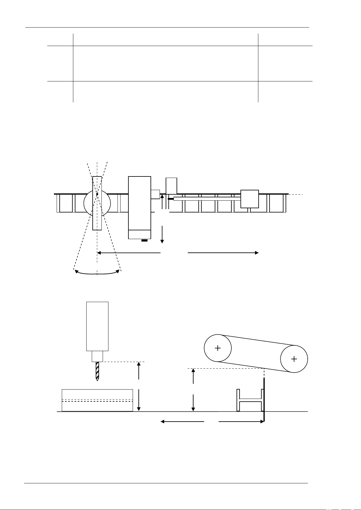
Origins and sign conventions of the axes
NOTE The above pictures refer to a 1001 DFB machine with right datum line (represented by the thick
line); the system can be assembled with left datum line (in accordance with the selected layout).
AXX
0
-
+
AXY
AMM
-
+
AXR
+
-
AXY = 0
AMM = 0
AXZ = 0
+
-
AXZ
AXS = 0
+
-
AXS
AXY
AMM
AXY = 0
AMM = 0
-
+

Model 1001 DFB Programming and operating manual
FICEP S.p.A. 15
Controls and signalling
Main electric cabinet
On the electric cabinet, there are the main switch and the “RESET” push-button with blue warning light.
To power the line it is necessary to rotate the main switch in “ON” position; to start up the line it is neces-
sary to push the “RESET” push-button to switch the blue warning light OFF. Meaning of the blue warning
light: line powered but not ready.
Switching ON procedure
On the others electric cabinets, there are no controls or signalling for the operator.
ON
OFF
ON
OFF
1 ÷ 2 seconds
1)
2)
3)
RESET

Programming and operating manual Model 1001 DFB
16 FICEP S.p.A.
Operator’s position
The operator’s position, connected to the drilling machine, is build up from a colour video, some push-
button stations and a PC keyboard.
Through screen and keyboards, the operator can program and completely control the line.
1) Main push-button panel: push-button and selectors switches necessary for the manual or auto-
matic execution of the main operative functions.
2) Colour screen: with touch screen function
3) Auxiliary push-button panel: this includes special functions typical of each line (ex. vices,
pincher controls, etc…)
In this zone, there is an emergency push-button with mechanical reset. When activated, all
actuators on the machine and the auxiliary circuits are immediately switched OFF. To re-
store the normal functioning, it is necessary to unlock the push-button (depending on the
different model it is required to pull or to clockwise rotate the red head) and to push again
the “RESET” push-button with blue warning light sideways to the main electric switch.
Another emergency push-button is on the portable push buttons panel for maintenance
operations (see “Portable push buttons panel for service operations”, page 38).
4) Controls and protections zone: Key type selector switch to lock the machine in safety mode for
tool setup, STOP push-button for drilling cycle and protections alarm RESET push-button (acti-
vated by interruption of protection barriers round the machine, if provided).
5) Alphanumeric keyboard: standard PC keyboard having letters, numbers and others symbols; it
is used to input data and information, to edit programs, etc…
Main and auxiliary push-button panels - Push buttons with LED included may properly be considered true
two-position selector switches:
If the LED is not illuminated, the selector switch is in OFF position and the relevant command is
not activated. To move the selector switch to ON position, just press the push button and wait till
when the LED is illuminated.
If the LED is illuminated, the selector switch is in ON position and the relevant command is acti-
vated. To move the selector switch to OFF position, just press the push button and wait till when
the LED is no more illuminated.
If the LED is blinking, it signals the system availability to accept the command of the push-button.
1
3
4
5
2
Model 1001 DFB Programming and operating manual
FICEP S.p.A. 17
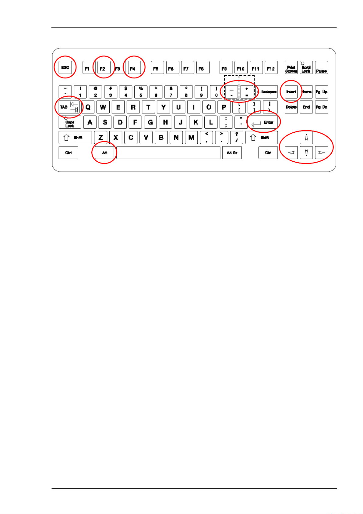
Alphanumeric PC keyboard
Some keys have particulars functions:
ESC:
To escape from an application, coming back to the previous level.
TAB:
To move the cursor on different boxes.
ENTER:
To open the selecting window evidenced by the cursor, or to confirm the execution
of a common request (OK).
ARROWS:
To move the cursor in the selected direction, on a field or on a list.
F2:
To modify data already input or to confirm modifications executed.
F4:
To open lists of options to be used when programming or in processing operations
(Aided programming).
INSERT:
To move the curser on a blank table, and input new working data (it is named INS
in the example).
+/- :
To increase (+) or decrease (-) the axes speed, or to program negative/positive
incremental or absolute coordinates.
DELETE
To delete characters on the right of the cursor position
BACKSPACE
To delete characters on the left of the cursor position
Keys combinations:
ALT+H:
Opens the windows describing messages.
ALT+TAB:
Enables to select one of the already opened applications or activates the actual
page on the video
CTRL+ESC:
Opens the Windows menu list (ESC to close)
CTRL+X:
Stores and removes the data evidenced by the cursor
CTRL+C:
Stores the data evidenced by the cursor to be copied
CTRL+V:
Paste the stored data in the actual position of the cursor

Programming and operating manual Model 1001 DFB
18 FICEP S.p.A.
Blank page

Model 1001 DFB Programming and operating manual
FICEP S.p.A. 19
CHAPTER 2: CNC DESCRIPTION
Introduction of the CNC operating environment
The CNC operating environment is called “Minosse” and the previous picture represents the introduction
screen page.
There are five graphic push-buttons which define four different working sections (Programming, Execu-
tion, Installation and Servicing, Communication CAM) and the system shut down (“OFF”).
To enter one of the four main pages or to shut down the system, it is necessary to press the key corre-
sponding to the underlined character of the word of each graphic push button or press the screen in the
graphic push-button corresponding area.
Press the ESC key on the PC keyboard to return to the first page.
Touch screen
To carry out a touch screen command, just gently touch the area on the screen where the relevant push-
button is displayed.
Clean the screen only when the system is shut down to avoid wrong commands.
Fixed elements for all pages
The background of all pages (1) is the one shown in the following picture.

Programming and operating manual Model 1001 DFB
20 FICEP S.p.A.
2, 3 Box signalling a current alarm, error or messages (numerical code and brief description). To open
the alarm window press the combination ALT+H on the PC keyboard.
4 shows the current time in the following format: hh:mm:ss = hours:minutes:seconds, of the clock
inside the PC.
5 per cent value of the AXX axis movement speed (from a min. of 10% up to a max. of 100%). The
value, which has been set, is displayed by a filling bar and by a value written as percent. The speed
variation is made by 10% steps.
6, 7 by “+” and “-“ graphic push buttons or the corresponding keys of the PC keyboard, the operator can
increase or decrease the speed.
This manual suits for next models
1
Table of contents
Popular Industrial Equipment manuals by other brands


transnorm
transnorm TS 2733 operating instructions

Atlanta Attachment Company
Atlanta Attachment Company 1390HCB Technical Manual & Parts Lists

BERRIDGE
BERRIDGE TZ-21 Operation manual

Can Industrial
Can Industrial W40H21P Series Assembly manual

Grundfos
Grundfos IO 113 Installation and operating instructions

Simplex
Simplex LT0290 User manual and reference guide


