Fidelity Measurement AFM18 User manual
AFM18 / FM18 / FM18S
ELECTRONIC WEIGHING INDICATOR
OPERATION MANUAL
PLEASE READ THIS MANUAL VERY CAREFULLY BEFORE ATTEMPT TO
OPERATE THIS INSTRUMENT
Specifications subject to change without prior notice
V118 December 2015 Rev1

1
www.fi-measurement.com

2
www.fi-measurement.com
Content
1. Installation......................................................................................................5
2. Specifications .................................................................................................6
3. Keys, Display & Connections.........................................................................7
3.1 Keys & Display Indicators.........................................................................7
3.2 Connection Points ..................................................................................11
4. Getting Started .............................................................................................13
4.1 Built-In Rechargeable Battery.................................................................13
4.2 Power Adaptor........................................................................................13
4.3 Connecting Other Devices......................................................................14
4.3.1 Connection with Weighing Platform (Load Cell)..............................14
4.3.2. Connecting RS232 to Computer.....................................................14
4.3.3 Connecting RS232 to Printer (DB25)...............................................15
4.3.4 Connecting the Optional External Relay Output Module.................15
4.3.5 Connecting to TTL Relay Devices by Others...................................15
4.3.6 Connecting the Optional Wireless Data Communication Module....15
4.3.7 Connecting Devices by Others to TTL Comport..............................16
4.4 Setting up the Preferred Operation Parameters.....................................16
5. Initial Setup...................................................................................................18
5.1 Internal Settings......................................................................................18
5.2 How to Enter & Select Internal Function ................................................18
5.3 Key Function during Internal Function Mode..........................................18
5.4 Internal Function Table ...........................................................................19
6. Instruction for Use........................................................................................25
6.1 Power On................................................................................................25
6.2 Start Weighing ........................................................................................25
6.3 About Weigh Unit Conversion.................................................................25
6.3.1 Conversion between Metric Weight Units (kg and g).......................25
6.3.2 Conversion between Metric (kg and/or g) and Imperial (lb) weight
units (F9)...................................................................................................26
6.4 Tare Off the Weight Of A Container ........................................................26
6.4.1 Manual Tare.....................................................................................26
6.4.2 Auto Tare (F12)................................................................................26
6.4.3 Repeated Tare (F13)........................................................................27
6.4.4 Preset Tare (F63).............................................................................27
6.5 Memory Accumulation Function .............................................................28

3
www.fi-measurement.com
6.5.1 To Accumulate a Transaction to Memory .....................................28
6.5.2 Memory Recall and Clearance ........................................................28
6.6 Function Modes......................................................................................29
6.7 To Enter & Quit from Supplementary Function Mode.............................29
6.7.1 To Enter a Function Mode................................................................29
6.7.2 To Enter & Quit from a Function Mode ............................................29
6.8 Piece Count Function.............................................................................29
6.8.1 Sampling Process............................................................................30
6.8.2 Shift among Quantity, Average Piece Weight and Weight Info........30
6.8.3 To quit Piece Count Function...........................................................30
6.9 Percentage Function ..............................................................................31
6.9.1 To Quit Percentage Function ...........................................................31
6.10 Animal Weighing Function ................................................................31
6.10.1 Weighing Animal............................................................................33
6.10.2 To Update Weight Value Manually.................................................33
6.10.3 To Quit Animal Weighing Function.................................................33
6.11 Checkweighing Mode ........................................................................34
6.11.1 To Trigger Checkweighing Mode 1 and Mode 2.............................34
6.12 Standard / Dynamic Checkweighing Mode (F25 = Mode 1).................35
6.12.1 Relay Output Assignment Table (F25 = Mode 1)...........................35
6.12.2 About Near Zero Value (F26).........................................................36
6.13 Inflow/Outflow Control Logic Mode (F25 = Mode 2).............................37
6.13.1 Diagram: - Inflow / Outflow ............................................................37
6.13.2 Relay Output Assignment Table (F25 = Mode 2)...........................37
6.14 Constant Feeding (F25 = Mode 3) & Dispensing (F25 = Mode 4) Modes
......................................................................................................................38
6.14.1 Control Parameters........................................................................38
6.14.2 Key Functions during Operation and Parameters Setting.............40
6.14.3 To Enter and Set Parameters for Mode 3 & Mode 4......................41
6.14.4 To Trigger/Stop Feeding / Dispensing Mode 3 and Mode 4...........41
6.14.5 Constant Feeding and Dispensing Control Logic Outputs.............41
6.15 Constant Feeding Mode .......................................................................42
6.15.1 Constant Feeding Illustration System Block Diagram ...................42
6.15.2 Constant Feeding Sequence Diagram...........................................43
6.15.3 Constant Feeding Sequence Description......................................43
6.15.4 Constant Feeding Auto Printout.....................................................45

4
www.fi-measurement.com
6.16 Constant Dispensing Mode ..................................................................46
6.16.1 Constant Dispensing Illustration System Block Diagram...............46
6.16.2 Constant Dispensing Sequence Diagram......................................47
6.16.3 Constant Dispensing Sequence Description .................................47
6.16.4 Auto Reservoir Refill Function .......................................................49
6.16.5 Auto Reservoir Refill Sequence Description..................................49
6.16.6 Constant Dispensing Auto Printout................................................50
7. RS232 Data Output Mode............................................................................52
7.1 Auto Weight Format String ....................................................................52
8. Ticket / Receipt Printing ...............................................................................53
8.1 Standard Print Output Format ...............................................................53
8.1.1 Standard Output Print Format..........................................................53
8.1.2 Standard Output Print Format of Checkweighing Mode ..................56
8.2 Custom Print Output Format .................................................................59
8.2.1 To Edit Custom Print Output Format................................................59
8.2.2 Print Output Format Variants Table..................................................60
8.2.3 Edit Sample for Custom Print Output Format..................................61
9. Label Printing (LP-50 or Compatible)...........................................................62
9.1 Label Format Groups & Label File Names.............................................62
9.1.1 For 1 (Label Format Group 1)..........................................................62
9.1.2 For 2 (Label Format Group 2)..........................................................63
9.2 Label Programming................................................................................63
9.2.1 Label Programing Information Table................................................64
9.2.2 Label Programming Sample ............................................................65
10. Battery Power & Recharging......................................................................66
10.1 Symbols And Remaining Power...........................................................66
10.2 Battery Operation Time.........................................................................66
10.3 Recharge Battery..................................................................................66
11. Error Codes................................................................................................68
12. Daily Care & Maintenance .........................................................................69
Appendix A: - Bi-Directional Communication Jumper Setting..........................70
Appendix B: - Bi-Directional Communication Commands ...............................71
A. Direct Control Commands (F18 = Mode 1, 2 And 4)................................71
B. Information Request Commands (F18 = Mode 4) ...................................71
B.B.1 Information Request Commands Table...........................................72
B.B.2 Data Format ..................................................................................73

5
www.fi-measurement.com
1. Installation
Because of metrological legislation, installation / some metrological parameter
settings are limited to be done by authorized personnel only. Do not attempt to
change any of the built-in parameters. Contact your dealer for installation and
technical assistance.
Caution: -
This instrument is legal for trade only when it is sealed (and/or stamped) and
bearing a serial number. Do not attempt to break the seal (or stamp) affixed to
this instrument and/or remove the serial number. Contact your dealer for more
information and after sales service.
For most accurate weighing result, do not use the unit in where or when the
environment condition falls beyond as those listed on Specifications.
Do not attempt to open this instrument or conduct any trouble shootings.

6
www.fi-measurement.com
2. Specifications
Maximum Capacity
Single Range Mode: -
•Max = 1 ~ 999,999 (kg or lb)
Dual Range Mode: -
•Max1 = 1 ~ 999,998(kg or lb)
•Max2 = 2 ~ 999,999(kg or lb)
•Condition = Max1 <Max2
External Resolution
Single Range Mode: -
•Recommend = 15,000 ~ 30,000
•High = 30,000 ~ 60,000
Dual Range Mode: -
•Recommend (Max2/ d1) = 15,000 ~ 30,000
•High (Max2/ d1) = 30,000 ~ 60,000
•Condition = d1 <d2
Weight Units
Kg, g, lb
Offset Range
≥0.2mv (10000 Count)
Tare Range
- Max (Subtractive Tare)
Max. Measuring Range
15 mV
A/D Sampling Speed
15 times/ second
Power Voltage
Requirements
Built-in Rechargeable Battery = 6V DC
External Power Adaptor = 12V DC, 800mA
Load Cell Excitation
Voltage
5 VDC
Minimum/Maximum Load
Cell Impedance
350Ω/1000Ω
Load Cell Connection
Supports 4-wire and 6-wire Load Cell
Connections
Maximum Load Cell
Connection
8 x 350ΩLoad Cells, or
16 x 700ΩLoad Cells
Operation Environment
-10 ~ 40oC. Non-condensed. R.H.≦85%
In the interest of improvement, specifications may change prior to notice
7
www.fi-measurement.com
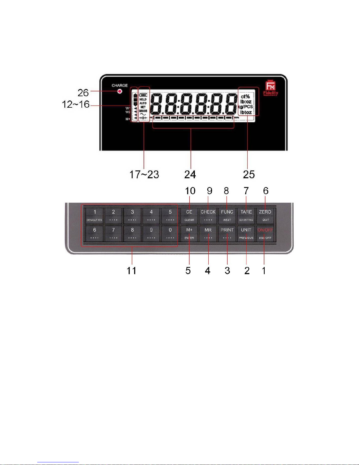
3. Keys, Display & Connections
3.1 Keys & Display Indicators
1. ON/OFF KEY
Press this key to turn this instrument on or off.
2. UNIT KEY
Press this key to shift among various weight units (if weight unit conversation
is enabled).

8
www.fi-measurement.com
3. PRINT KEY
1
Press this key to print the results to a computer or a printer through the
RS-232 output.
4. MR KEY
Press this key to recall total stored transactions.
5. M+ KEY
Press this key to accumulate current weight to memory manually.
6. ZERO KEY
Press this key to set weight displayed to zero when an empty scale has drifted
away from a true zero reading.
7. TARE KEY
Press this key to tare off the weight of a container.
8. FUNCTION KEY
Press this key to shift between percentage, piece count and animal
2
mode.
9. CHECK FUNCTION
Press this key to start check weighing function and to enter value for Hi and Lo
limits.
10. CE KEY
Press this key to clear value entered.
11. NUMERIC KEYS
Numeric keys 0 ~ 9.
1
This key is also used to accumulate the current weight value to memory when internal function
F17 is set to ON.
2
When F11 = ON.

9
www.fi-measurement.com
12. CHECK SYMBOLS
•Hi = Weight reading is higher than the Hi limit entered,
•OK = Weight reading is in between than the Lo and Hi limits entered,
•Lo = Weight reading is lower than the Lo limit entered.
13. W1INDICATOR
3
(When under dual weighing range mode
4
) Visible when this instrument is in the
first weighing range (W1).
14. W2INDICATOR
5
(When under dual weighing range mode) Visible when this instrument is in the
second weighing range (W2).
15. SPARE
Blank, no function assigned.
16. M+ INDICATOR
Visible when the total accumulated weight value is being displayed.
17. BATTERY POWER / LEVEL INDICATOR
Visible to show: -
•This instrument is being powered by the built-in rechargeable battery,
•Remaining battery level.
18. HOLD INDICATOR
(When under animal mode) Visible when weight reading being displayed is a
frozen value.
19. AUTO INDICATOR
Visible when the instrument is in animal weighing function.
3
This indicator will not appear when this instrument is in single range mode.
4
This instrument can support two weighing ranges with different maximum capacities (Max) and
different scale intervals (d), each range extending from zero to its maximum capacity.
5
This indicator will not appear when this instrument is in single range mode.

10
www.fi-measurement.com
20. NET INDICATOR
Visible when the tare function is in effect. Weight reading shown is net value.
21. GROSS INDICATOR
Visible when gross weight reading is displayed.
22. STABLE INDICATOR
Visible when weight reading is stable.
23. ZERO INDICATOR
Visible when instrument is at true zero weight status.
24. CAPACITY TRACK BAR
The ratio (increment = 10%) of applied & remaining weighing capacities are
shown here.
25. WEIGHT UNITS AND FUNCTIONS
•% = Percentage (when Percentage Mode in function),
•kg = kilogram,
•PCS = Pieces (when Piece Count Mode in function),
•kg/PCS and g/PCS = Weight per piece (when Piece Count Mode in
function),
•lb = pound.
26. CHARGE STATUS INDICATOR
•Red color: Recharging battery,
•Green color: Charging completed.

11
www.fi-measurement.com
3.2 Connection Points
AFM18 & FM18
FM18S

12
www.fi-measurement.com
A. DC Jack Input for Indicator
External power adaptor (DC9 ~ 12V) is plugged in here. Do not plug in any
other power adaptor than the one which comes with this instrument.
B. RESERVED
C. LOAD CELL CONNECTOR (7-Pin)
•AFM18 & FM18: - Signal wires from load cell (or junction box) are
connected here.
•FM18S: - Thread though signal cable from load cell (or junction
box) here.
D. TTL RELAY OUTPUT PORT (If equipped)
•AFM18 & FM18: - Optional Control output port.
•FM18S: - Thread through optional control put cable here.
E. TTL COMPORT (if equipped)
•AFM18 & FM18: - Comport 2 (serial).
•FM18S: - Thread through cable of Comport 2 (serial).
F. RS232 COMPORT
•AFM18 & FM18: - Comport 1 (serial or TTL)
•FM18S: - Thread through cable of Comport 1 (serial or TTL)

13
www.fi-measurement.com
4. Getting Started
In order to obtain an accurate weighing result, the weighing platform must be
placed on a strong and level surface. Avoid using the platform and this
instrument in environment where excessive wind flow, vibration and extreme
temperature change exist
General Warnings: -
•The instrument is not an explosion proof device.
•The instrument is not a water proof device.
•Do not open the instrument, no user serviceable parts inside. Always
contact your dealer for service.
•The instrument not to be subject to shock, excessive vibration or
extremes of temperature (before or after installation).
4.1 Built-In Rechargeable Battery
The instrument is equipped with a built-in rechargeable battery. Before first
time use, recharge it for at least 8 hours to ensure the best battery
performance.
4.2 Power Adaptor
Before plugging in the power adaptor, check and make sure the input voltage
of the adaptor matches with output voltage of the electricity outlet. If not,
contact your dealer immediately.
Note: - for FM18S
The DC input connector and the output plugs of the power adaptor both comes
with a cover. Always screw tightly the cover to the DC input connector when
not used and battery recharge is in process.
14
www.fi-measurement.com
4.3 Connecting Other Devices
6
4.3.1 Connection with Weighing Platform (Load Cell)
Connect this instrument with a weighing platform (load cell) through LOAD
CELL CONNECTOR located at the back according to the below pin
assignment table.
If a 4-wire load cell or junction box is used, short-circuit pin 1 & 2 and pin 3 & 4.
Otherwise, this instrument will not work.
LOAD CELL
CONNECTOR PIN #
ASSIGNMENT
1
EXCITATION +ve
2
SENSE +ve
3
EXCITATION –ve
4
SENSE –ve
5
SIGNAL +ve
6
SIGNAL –ve
7
GROUND
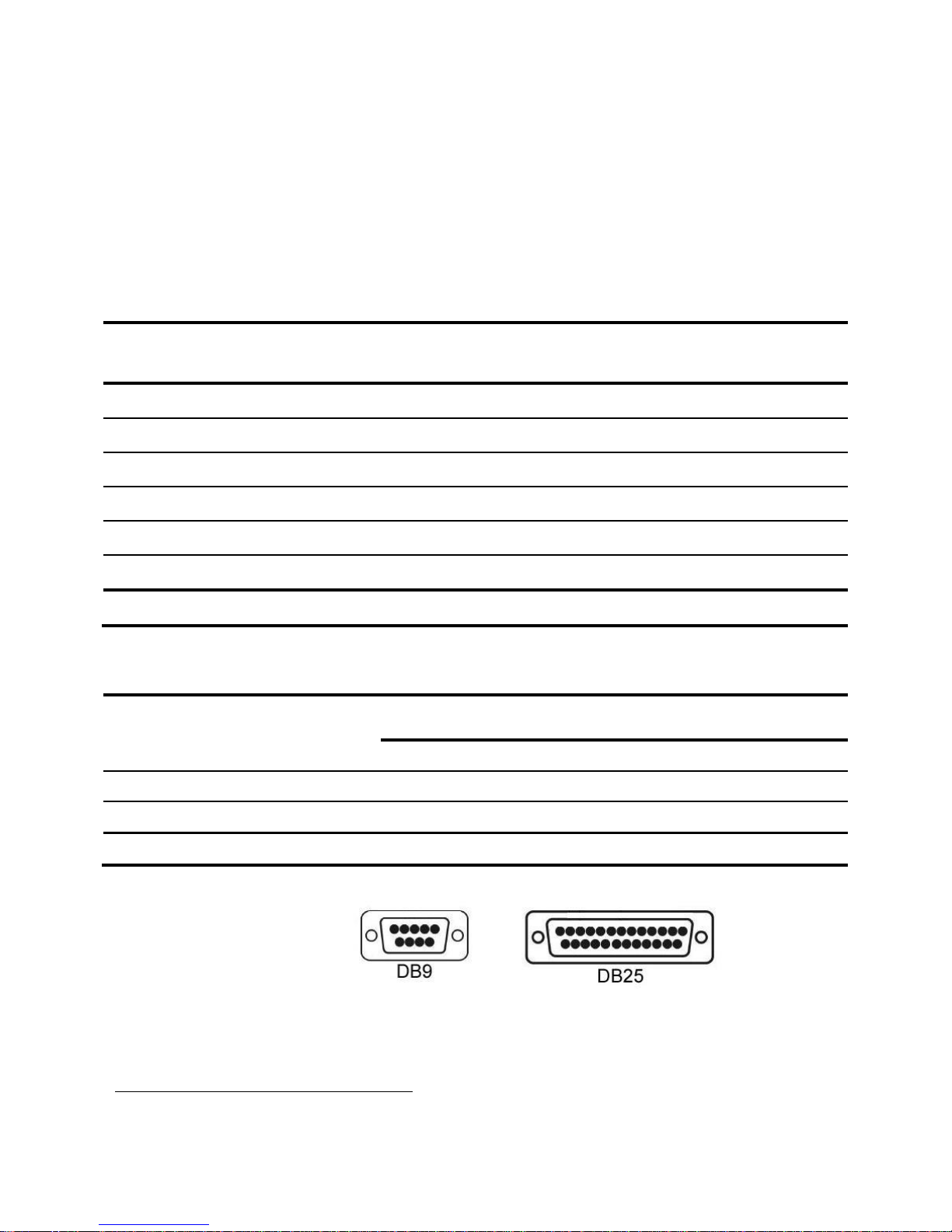
4.3.2. Connecting RS232 to Computer
RS232 COMPORT ON
INSTRUMENT
COM PORT ON COMPUTER
(DB9)
(DB25)
2 = RXD
3 = TXD
3 = TXD
3 = TXD
2 = RXD
2 = RXD
5 = GND
5 = GND
7 = GND
6
Turn this instrument off and cut off power before making any connections or disconnections.

15
www.fi-measurement.com
4.3.3 Connecting RS232 to Printer (DB25)
RS232 COMPORT (DB9) ON
INSTRUMENT
COMPUTER COM DB25
2 = RXD
3 = TXD
3 = TXD
2 = RXD
5 = GND
7 = GND
4.3.4 Connecting the Optional External Relay Output Module
If the optional relay output module is purchased, simply plug in the DB-25
connector of the relay output module to the TTL & relay output port by using
the accessory enclosed.
4.3.5 Connecting to TTL Relay Devices by Others
Follow the below TTL RELAY OUTPUT PORT PIN ASSIGNMENT TABLE for
connection.
This instrument provides low-active TTL relay signals. Do not connect the TTL
relay output port to any other non-TTL relay devices; they may cause
unrecoverable damages to this instrument.
TTL RELAY OUTPUT PORT PIN ASSIGNMENT TABLE (LOW-ACTIVE)
RELAY OUTPUT PIN #
ASSIGNMENT
1
BUZZER
3
LO
5
OK
7
HI
8
DC+5v Output
14
Ground
4.3.6 Connecting the Optional Wireless Data Communication Module
If the optional WM-SP wireless data communication module is purchased,
simply plug it into the TTL COMPORT.

16
www.fi-measurement.com
4.3.7 Connecting Devices by Others to TTL Comport
Follow the below TTL COMPORT PIN ASSIGNMENT TABLE for pin
assignment.
This instrument provides low-active TTL signals. Do not connect the wireless
data communication port to any other non-TTL devices; this may cause
unrecoverable damages to this instrument.
TTL COMPORT PIN ASSIGNMENT TABLE (LOW-ACTIVE)
TTL / WIRELESS DATA COMPORT
WIRELESS DATA
COMMUNICATION MODULE OR
DEVICES
2 = RXD
3 = TXD
3 = TXD
2 = RXD
5 = GND
5 = GND
9 = +5V Output
9 = +5V Input
Notes: -
1. Default setting of wireless data communication = send only. Position of
jumper J1 on main board needs to be changed in order to trigger
wireless data communication receive function (if it is the case, receive
function of the RS232 comport will then be disabled). Contact your
dealer for more information.
2. This instrument supports bi-directional data for either the RS232
comport or the TTL comport. Default setting of: -
•RS232 = bi-directional,
•TTL comport = single direction (transmission only).
If bi-directional TTL data communication is required, adjust jumper setting on
board. On board jumper setting may be required, refer to Appendix A
Bi-Directional Communication Jumper Setting for detailed information.
4.4 Setting up the Preferred Operation Parameters
Set all preferred operation parameters according to 5.4 Internal Function
Table.

17
www.fi-measurement.com
Notes: -
1. F1~F26 are accessible without restriction,
2. F60~F66 are restricted functions, which may request a password or
hardware key to access,
3. F80 ~ F99 are restricted functions, which may request a password or
hardware key to access. These functions are usually for dealer and
authorized personnel only and all settings these functions are monitored
and recorded. Do not change any settings of these functions to avoid
operation errors.

18
www.fi-measurement.com
5. Initial Setup
5.1 Internal Settings
Application parameters can be checked and set through internal functions.
Refer to 5.4 for description of all internal functions.
5.2 How to Enter & Select Internal Function
Follow the below steps to enter and select desired parameter of an internal
function.
a. Turn this instrument off and on again,
b. Press [TARE] during countdown,
c. Display F1,
d. This instrument is now in internal function,
e. Quick access to a function number
•Press [1] to go to F10,
•Press [2] to go to F20,
•Press [6] to go to F60 (for dealer and authorized personnel only),
•Press [8] to go to F80 (for dealer and authorized personnel only),
•Press [9] to go to F99 (for dealer and authorized personnel only),
•Press [0] to go to F1.
5.3 Key Function during Internal Function Mode
•[M+] = Enter, save and return,
•[ZERO] = Quit without saving,
•[FUNC] = Go next,
•[UNIT] = Go previous,
•[CE] = Clear,
•[TARE] = Go to internal function during power on countdown, or set F1
value being shown to zero and to display the net span gain by applying
additional load applied.
19
www.fi-measurement.com
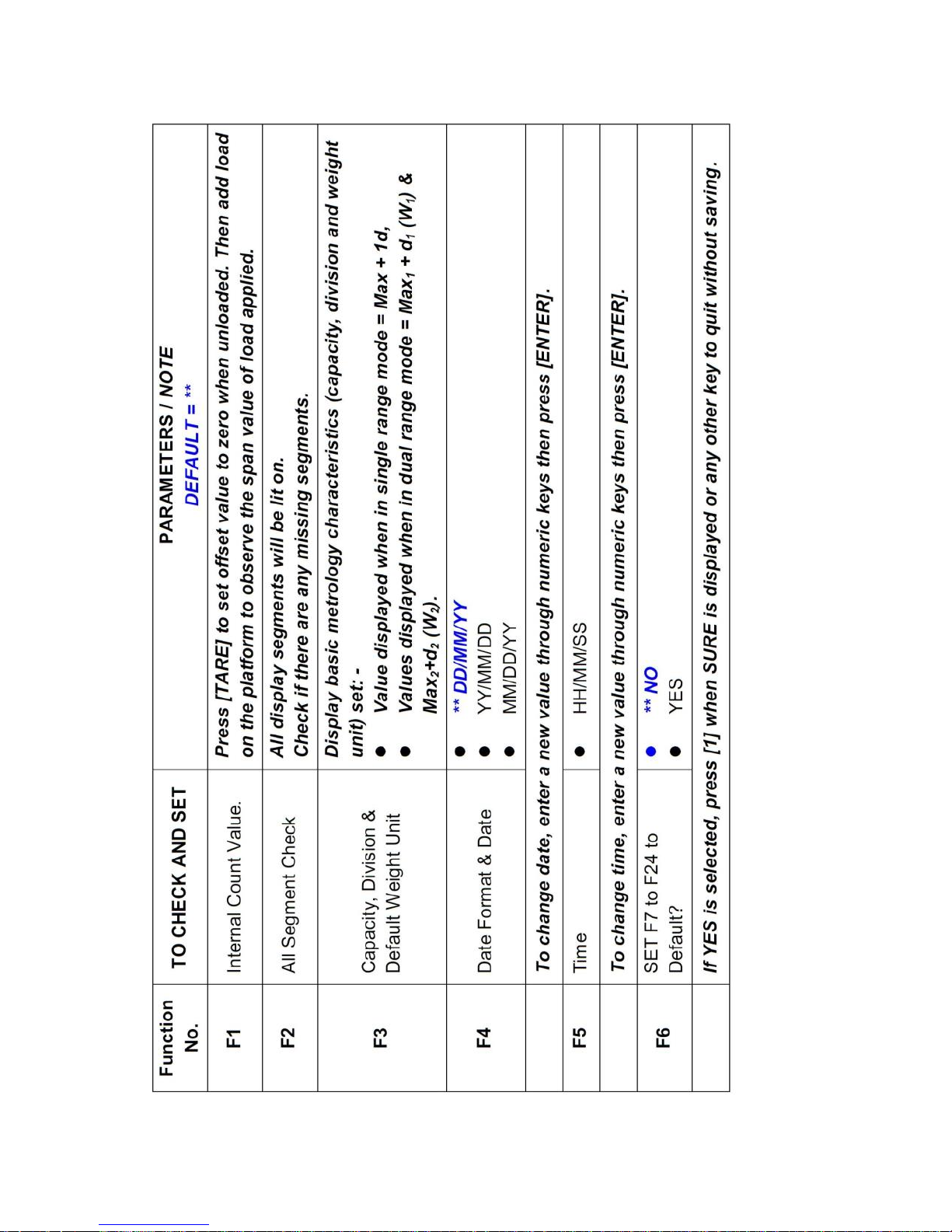
5.4 Internal Function Table
This manual suits for next models
2
Table of contents
Popular Accessories manuals by other brands


Belkin
Belkin SPORTCOMMAND FOR IPOD user manual

SOMFY
SOMFY Oximo WireFree Battery Stick instructions

Pepperl+Fuchs
Pepperl+Fuchs RMS-G-RC Brief instructions

Eufficio
Eufficio Innera Piatto installation instructions

Ventura
Ventura Prenox FREESTANDER 2009 Erection Instructions

Trivita
Trivita Essential Oils Diffuser Instructions & Care

ipf electronic
ipf electronic UT360321 manual

Elkay
Elkay EFOA Installation, care & use manual

PCB Piezotronics
PCB Piezotronics 622A01 Installation and operating manual

2gig Technologies
2gig Technologies ADC-IS-300-LP installation guide

enika
enika P8 T TempRh IP quick start guide

Rittal
Rittal SK 3185830 Assembly and operating instructions