FIEDLER FLA 1250 H User manual

Operating Instructions
FIEDLER®
Leaf vacuum machine
FLA 1250 H
HAKO Citytrac 4200


FLA 1250
INNOVATIVE TECHNOLOGY FOR ALL SEASONS
These operating instruction must always be kept close to the machine
in the driver's cab!
Operating Instructions
FIEDLER®
Leaf vacuum machine
FLA 1250 H
Dear Customer
With this
FIEDLER®
product,
you have selected a professional machine that
guarantees the highest quality and reliability.
We thank you for trusting
us.
We ask you to completely read through
the following instructions before starting,
so that you can use all the advantages of our products.
Machine No.: …………….

Date of publication: 12. June 2013

FLA 1250 H
INNOVATIVE TECHNOLOGY FOR ALL SEASONS
EU Declaration of Conformity
in accordance with the EU Machine Guideline 2006/42/EU dated 17 May 2006, Annex II A
Manufacturer: FIEDLER Maschinenbau und Technikvertrieb GmbH
Dresdner Straße 76c
D-01877 Schmölln-Putzkau
Tel.: +49 (0)3594 745 800
Person responsible for the
technical documentation: State approved technician
Maik Winkler
FIEDLER Maschinenbau und Technikvertrieb GmbH
Dresdner Straße 76c
D-01877 Schmölln-Putzkau
Description of the machine:
Product description: leaf vacuum machine FLA 1250 H
Function: Mechanical removal of leaves and light material like leaves (light
litter) in the green areas, pavements, parking places and roadsides
and/or footpaths
Date of manufacture: …………………
We declare herewith that the above-mentioned machine in its conception and type as well as in the
design being sold by us conforms to all pertinent regulations of the Machine Guideline 2006/42/EU.
If the machine is modified without our authorization, this declaration will become invalid.
The above-mentioned machine meets the requirements of the following guidelines:
•M
achine Guideline 2006/42/EU
The following harmonized standards have been used:
•DIN EN 12100-1 Safety of machines – basic terms, general layout guidelines, Part 1: Basic
terminology, Method
•DIN EN 12100-2 Safety of machines – basic terms, general
layout guidelines, Part 2: Technical guidelines and specifications
•DIN EN 60204-1 Safety of machines – electrical fittings of
machines, Part 1: general requirements
•DIN EN ISO 13849 Safety of machines – safety-related parts of control units
Schmölln-Putzkau, 18 October 2011 Frank Fiedler, BSc in engineering
Managing Director:

FLA 1250 H Table of contents
INNOVATIVE TECHNOLOGY FOR ALL SEASONS
1 General ................................................................................................................................ 8
2 Safety ................................................................................................................................... 9
2.1 General Instructions................................................................................................................... 9
2.2 Obligations of the operator......................................................................................................... 9
2.3 Permitted operators and the workplace of the operator.............................................................. 9
2.4 Symbol – and clarification of the instructions ........................................................................... 10
2.5 Proper use............................................................................................................................... 10
2.6 Safety labels on the machine................................................................................................... 10
2.7 Safety equipment..................................................................................................................... 11
2.8 Safety measures in the operation ............................................................................................ 11
2.9 Hazard due to the hydraulic energy ......................................................................................... 13
2.10 Machine noise........................................................................................................................ 13
2.11 In an emergency.................................................................................................................... 13
3 Technical data ................................................................................................................... 14
4 Assembly ........................................................................................................................... 15
4.1 Mounting the chassis frame to the machine ............................................................................. 15
4.2 Mounting on the vehicle ........................................................................................................... 16
4.3 Adjusting the working height .................................................................................................... 16
4.4 Dismantling the machine.......................................................................................................... 17
5 Hydraulics.......................................................................................................................... 18
5.1 Connections on the vehicle...................................................................................................... 18
5.2 Adjustment of the throttle valve................................................................................................ 18
6 Operation ........................................................................................................................... 19
6.1 Vehicle operation..................................................................................................................... 20
6.2 Operation of the working device............................................................................................... 20
6.2.1 Side brush/pick-up shaft.................................................................................................... 20
6.2.2 Large object flap................................................................................................................ 21
6.2.3 Collection container........................................................................................................... 21
6.2.4 Transport on the vehicle .................................................................................................... 21
7 Work on the machine........................................................................................................ 23
7.1 Adjusting the working height .................................................................................................... 23
7.2 Removing blockages ............................................................................................................... 23
7.3 Changing the cutter blader....................................................................................................... 24
7.4 Changing the pick-up shaft ...................................................................................................... 25
7.4.1 Disassembly...................................................................................................................... 25
7.4.2 Assembly .......................................................................................................................... 29
8 Maintenance and decommissioning ............................................................................... 30
8.1 Maintenance ............................................................................................................................ 30
8.1.1 Work before each use ....................................................................................................... 30
8.1.2 Work after each use: ......................................................................................................... 30

Table of contents FLA 1250 H
INNOVATIVE TECHNOLOGY FOR ALL SEASONS
8.1.3 Weekly work, or every 30 operating hours:........................................................................ 31
8.2 Decommissioning .................................................................................................................... 31
8.2.1 Temporary decommissioning............................................................................................. 31
8.2.2 Removal from service........................................................................................................ 31
Table of Contents
Tab. 1 Technical data........................................................................................................................ 14
Tab. 2 Briefing................................................................................................................................... 32

FLA 1250 H General
8
INNOVATIVE TECHNOLOGY FOR ALL SEASONS
1 General
These operating instructions give information about all the models, series and special attachments
of your machine/assembly device available at the time of the publication of these operating
instructions.
There may be country-specific deviations.
Please note that your model need not be equipped with all the functions described. This is also
applicable to the safety systems and functions. There may be deviations in the description or the
illustrations because of this.
The scope of the function and the list of special equipment have been given in the original purchase
agreement documents of your machine/attachment device.
In case of any queries related to equipping and operation, you can contact any authorized
FIEDLER®
dealer.
Special information on the carrier vehicles, such as assembling, installing and operation can be
found in the Annex of these operating instructions or in the operating handbook of the
corresponding vehicle manufacturer.
These operating instructions are an important document and must always be kept in the vehicle!

Safety FLA 1250 H
9
INNOVATIVE TECHNOLOGY FOR ALL SEASONS
2 Safety
2.1 General Instructions
The leaf vacuum machine FLA 1250 H has been manufactured in accordance with the current
level of technical expertise, the assembly guidelines of Hako – Werke GmbH and Multicar branch
of Hako – Werke GmbH.
Still, mishandling and incorrect operation can be hazardous:
•for the health and life of the operator and/or third party
•for the machine or other material objects of the operator
•for the problem-free operation of the machine
Therefore, the leaf vacuum machine must only be used for the purpose intended for it and
operated in a safe, perfect working order. Disturbances, which could compromise safety must be
removed completely.
2.2 Obligations of the operator
The operator is obligated to allow only those people to work on the leaf vacuum machine that:
•are at least 18 years old
•have a relevant driver's license and know the vehicle's operations
•have been technically briefed about the handling of the vehicle and the leaf vacuum
machine
•are familiar with the basic directives concerning occupational safety and avoidance of
accidents as well as the accident prevention guidelines of the Accident Prevention and
Insurance Association
•have read and understood the operating instructions and have confirmed it with their
signature
The operator is obligated to instruct his/her operating company that the key for unlocking
the access hatch must always be with the ignition key of the vehicle in order to ensure
that it can only be opened when the ignition is switched off!
If this requirement is not met and there are accidents as a consequence, all the liabilities
of the manufacturer are precluded!
(Refer to the last page of the operating instructions!)
It must be checked regularly that the personnel are working with safety in mind.
2.3 Permitted operators and the workplace of the operator
The leaf vacuum machine should only be operated, serviced and maintained by people that:
•are at least 18 years old
•have a relevant driver's license and know the vehicle's operations
•have been technically briefed about the handling of the leaf vacuum machine

FLA 1250 H Safety
10
INNOVATIVE TECHNOLOGY FOR ALL SEASONS
The workplace of the operator is exclusively in the driver's cab of the vehicle.
All people that must work with the vacuum machine must:
•read and understand these instructions and confirm this by signing on the last page
•follow the basic directives concerning occupational safety and avoidance of accidents as well
as the accident prevention guidelines of the Accident Prevention and Insurance Association
2.4 Symbol – and clarification of the instructions
WARNING!
Shows a possible hazardous situation
If this instruction is not followed, it can lead to death or grave injuries
CAUTION!
Shows a possible hazardous situation
Non-adherence to this instruction can lead to mild injuries or damage to the machine
IMPORTANT!
Shows user tips and useful information
Non-adherence to this instruction can lead to problems in the machine or in the
surroundings.
2.5 Proper use
The leaf vacuum machine is designed for the mechanical removal of leaves and
light materials like leaves (light litter) in green areas, pavements, parking places and footpaths.
The machine can only be mounted on a Hako Citytrac 4200 DA.
Proper use also includes the adherence to all the instructions from these operating
instructions and the adherence to the inspection and maintenance works!
2.6 Safety labels on the machine
Risk of injury due to moving parts!
–
It is prohibited to remove the safety equipment
during the operation!
Risk of injury due to the turning cutter shaft!
–
It is prohibited to remove the safety equipment
during the operation!
The cutter shaft runs for a minute after switching
off!

Safety FLA 1250 H
11
INNOVATIVE TECHNOLOGY FOR ALL SEASONS
Before using the leaf vacuum machine
–
Read the operating instructions!
In case of repairs and maintenance works
–
Stop the vehicle and remove the ignition key!
Follow the operating instructions!
2.7 Safety equipment
•The leaf vacuum machine FLA 1250 H has safety equipment. Before each use, it must be
ensured that this equipment is attached properly and is functioning correctly!
•Safety equipment must only be removed when the machine is at a standstill and secured
against restarting!
oHousing for pick-up shafts
oHousing on the blade cutter
oAccess hatches with locks
oChain guard
The access hatches must be kept closed during the operation; the key for it must always
be on the keyring for the ignition key!
2.8 Safety measures in the operation
WARNING!
Danger due to flying objects!
No person or animal should be within 5m of the machine when it is operational!
While operating in the proximity of public road traffic, the flashing warning
light must be kept on and the following traffic must be warned!
WARNING!
Risk of crushing in the lifting area of the leaf vacuum machine!
Maintenance and installation works must only be carried out when the turbine is
not operational, the vehicle is switched off and the hydraulic system is without
pressure.
Make sure that the access hatch is locked!
It must always be locked while operating the leaf vacuum machine.
WARNING!
Changed handling and steering of the vehicle!
Do not exceed a speed of 5km/h during the vacuuming work!
The maximum transporting speed must not exceed 50km/h!
WARNING!
Extra caution – increased front weight
The leaf vacuum machine will turn sideways if the steering wheel is turned too

FLA 1250 H Safety
12
INNOVATIVE TECHNOLOGY FOR ALL SEASONS
sharply!
WARNING!
Risk of injury due to the rotating sweeping brush and cutter blade!
The vacuum head must not be touched by the hands or feet when it is operational! It
is prohibited to insert or remove objects from the vacuum head during operation!
WARNING!
Breaking the collection hose and damage to the driver's cab!
The collecting hopper must be uncoupled while removing the leaf vacuum machine!
WARNING!
Risk of cutting and crushing by the cutter blade!
Manually turning the collecting shaft can cause the cutter blade to turn!
Never touch the area around the cutter blade!
The access hatches must be kept closed during operation, the key for it should
always be kept on the keyring for the ignition key!
CAUTION!
Damage to the engine due to dust in the vehicle radiator!
Check the vehicle's radiator every hour!
If required, clean when the engine is switched off and the vents are stationary.
CAUTION!
Damage to the hydraulic system due to increased hydraulic oil temperature!
Check the oil coolant and hydraulic hoses every hour!
•In addition to these operating instructions, the general and local regulations for
preventing accidents and for environmental protection as well as the regulations for
accident prevention of the Accident Prevention and Insurance Association must be kept
handy and followed!
•The machine must be checked for externally visible damage and the functionality of the
safety equipment before each use.
•Unauthorized modifications to the machine and its safety equipment are prohibited and
will preclude the manufacturer's liability!
•Bypassing and otherwise making the safety equipment ineffective is not permitted.
•All general safety and warning instructions must be kept in the machine in a legible form.
•These operating instructions must be kept in the driver's cab of the HAKO Citytrac
when the leaf vacuum machine is attached to it.

Safety FLA 1250 H
13
INNOVATIVE TECHNOLOGY FOR ALL SEASONS
2.9 Hazard due to the hydraulic energy
WARNING!
Risk of infection!
Hydraulic oil can cause skin rashes and other health problems!
Even a small amount of oil can penetrate the skin and cause serious injury!
Consult a doctor immediately in such cases!
WARNING!
Risk of injury due to spraying hydraulic oil!
The connection of the hydraulics must be made only when the vehicle is switched off
and the hydraulic system is without pressure!
IMPORTANT!
Possible environmental contamination!
Do not spill any hydraulic oil!
Take measures to collect any hydraulic oil that may have spilled!
The handling and disposal of hydraulic oils are subject to legal regulations!
Only people with special know-how and experience in hydraulics must handle hydraulic
equipment.
Check the hydraulic hoses regularly to ensure they are properly sealed!
They must be replaced regularly, even when there are no evident defects (see Maintenance
and inspection of the hydraulic unit in the vehicle's handbook).
2.10 Machine noise
The constant noise level of the machine is below 80dB.
Depending on the local conditions, there could be a higher noise level that could cause
difficulty in hearing due to the noise. In such cases, the personnel must have the necessary
safety equipment and/or safeguard themselves with safety measures.
2.11 In an emergency
Stop the vehicle and turn off the engine.
FLA 1250 H Technical data
14
INNOVATIVE TECHNOLOGY FOR ALL SEASONS
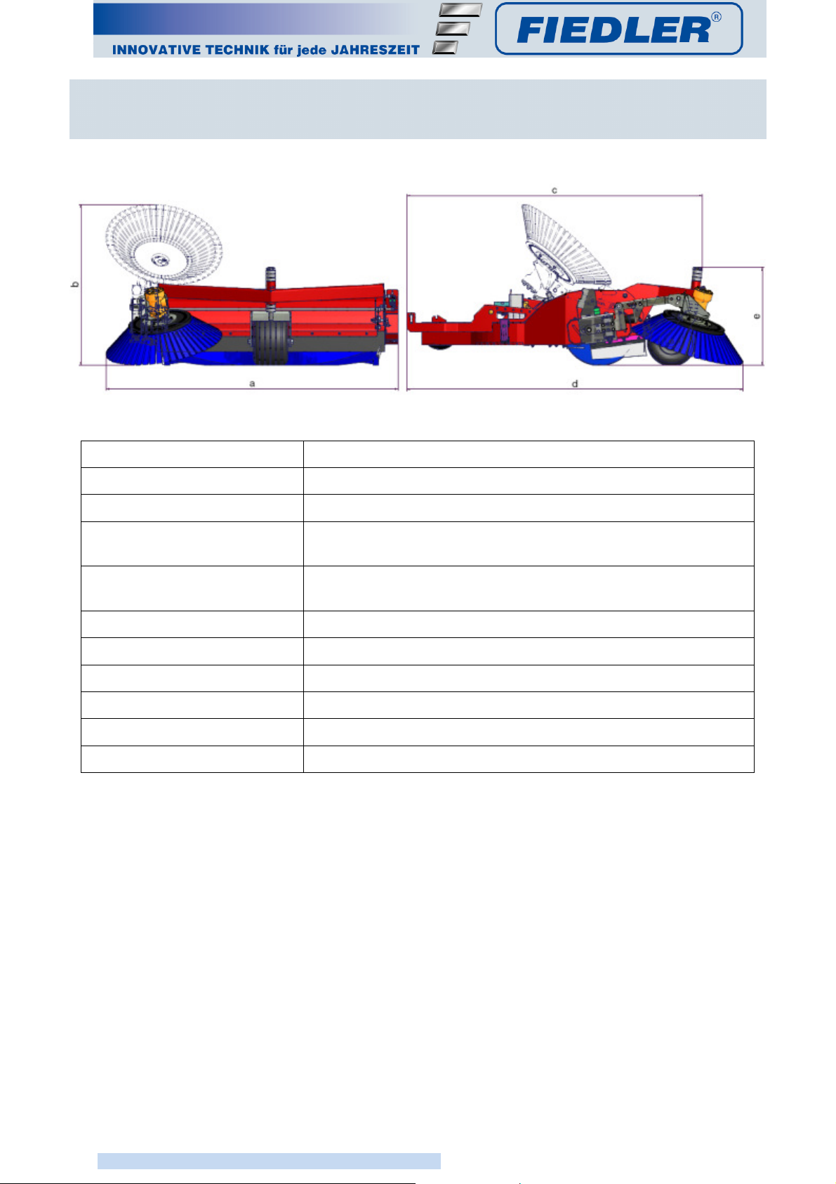
3 Technical data
a (machine width) 1,610mm
b (machine height, transport)
880mm
c (machine length, transport)
1,650mm
d (machine length, when
working)
1,850mm
e (machine height, when
working)
550mm
Work area 1.25m (1.50m with side brush)
Work width 1.25m (1.50m with side brush)
required oil quantity 40–45l/min at 180bar
Weight 200kg
Controls electro-hydraulically operated vehicle hydraulics
Hydraulic supply throughout the carrier vehicle
Tab. 1Technical data

Assembly FLA 1250 H
15
INNOVATIVE TECHNOLOGY FOR ALL SEASONS
4 Assembly
WARNING!
Risk of crushing in the lifting area of the leaf vacuum machine!
Maintenance and installation works must only be carried out when the turbine is
not operational, the vehicle is switched off and the hydraulic system is without
pressure.
Make sure that the access hatch is locked!
It must always be secured while working under the collector!
WARNING!
Risk of injury due to the rotating pick-up shaft and cutter blade!
The vacuum head must not be touched with the hands or feet during operation! It is
prohibited to insert or remove objects from the vacuum head during operation!
WARNING!
Breaking the collection hose and damage to the driver's cab!
The collecting hopper must be uncoupled while removing the leaf vacuum machine!
4.1 Mounting the chassis frame to the machine
The mounting is carried out with a Euro pallet and two open end spanners SW19.
1. Secure the machine to a Euro pallet to ensure it doesn't topple.
2. Hang the chassis frame from top, left, and right from the
stipulated points
3. tighten from both sides with a hexagonal screw M12×30
left holding
point
right holding
point
Chassis frame
Fig.
1
Assembling the chassis

FLA 1250 H Assembly
16
INNOVATIVE TECHNOLOGY FOR ALL SEASONS
4.2 Mounting on the vehicle
The mounting on the carrier vehicle without any tools!
1.Secure the vacuum machine on a level ground on a Euro pallet against toppling over
2.Remove the four retaining bolts, the assembly frame from the holders and remove all moving
objects from the coupling zones
3.Move the Citytrac slowly up to 20cm in front of the rear fastening points
connect the suction hopper of the Citytrac to the leaf vacuum machine in this position
4.Move the Citytrac as precisely as possible for the remaining 20cm to the leaf vacuum machine
– switch off the engine, switch on the ignition again and activate the floating position
5.Align the lower linkage eyes with the holes of the assembly frame and connect with the
provided mounting bolts
6.Secure the mounting bolts
7.Connect the vehicle hydraulic system to the machine's hydraulic system (also see Section 5.1)
8.If the leaf vacuum machine is hanging with the front mounting bolts, the Citytrac can be started
and the hoist can be lifted slowly until the rear holes of the collector are in position over the
rear fastening points on the lower linkage of the Citytrac – fasten in this position with the
required bolts and secure
4.3 Adjusting the working height
The working height can be adjusted without tools!
•to adjust the working height, raise the device completely so that the chassis hangs above
the ground
•by distributing the spacers on the top or bottom, the desired/required working height can
be set
1. remove the cotter pin
2. remove the wheel fork by pulling it down
3. distribute the spacers as desired – in case of first time assembly, the rings must be
spread out equally above and below the frame
4. replace the cotter pin
Fig.
2
Assembly on the Citytrac

Assembly FLA 1250 H
17
INNOVATIVE TECHNOLOGY FOR ALL SEASONS
The tyres air pressure should not exceed 2 bar, since it will otherwise lead to
unnecessary rubber wear by the scraper.
Fig. 3 Working height
4.4 Dismantling the machine
The dismantling is done in the reverse order of the assembly.
1. Lift the device completely
2. Switch off the ignition, apply the parking brake
3. Secure the vehicle against tipping over
4. Disconnect the hydraulics
5. Loosen the locking lever on the suction hopper and fold away downwards
(Work from the side, do not stand under the machine!)
6. Position the Euro pallet under the machine
7. Switch on the hydraulics and lower the hoist until the machine is on the Euro pallet
8. Remove the mounting bolts
9. Lower the hoist again until the machine is completely released from the vehicle
10. Drive the vehicle away carefully backwards
spacers
cotter pin
max.
2bar!

FLA 1250 H Hydraulics
18
INNOVATIVE TECHNOLOGY FOR ALL SEASONS
5 Hydraulics
5.1 Connections on the vehicle
IMPORTANT!
The hydraulic couplings can be under pressure.
Please follow the operating instructions of the vehicle!
5.2 Adjustment of the throttle valve
•Setting of the rotation speed of the pick-up shaft/side brushes
IMPORTANT!
If the throttle valve is turned all the way, the pick-up shaft and the side brush is
switched off.
Return line
Pressure
Leakage oil
Fig.
4
Front hydraulic connection
Throttle valve
Fig.
5
Rotational speed setting

Operation FLA 1250 H
19
INNOVATIVE TECHNOLOGY FOR ALL SEASONS
6 Operation
WARNING!
Danger due to flying objects!
No person or animal should be within 5m of the machine when it is operational!
Work only when the collection hose is attached.
While operating in the proximity of public road traffic, the flashing warning light must
be kept on and the following traffic must be warned!
WARNING!
Damage to the leaf vacuum machine and damage to the environment!
Never operate in water or other liquids!
WARNING!
Risk of crushing in the lifting area of the leaf vacuum machine!
Maintenance and installation works must only be carried out when the turbine and the
vehicle is switched off and the hydraulic system is without pressure.
Make sure that the access hatch is locked!
It must always be secured while working under the machine!
WARNING!
Changing the driving and turning behaviour of the vehicle
Do not exceed a speed of 5km/h during the vacuuming work!
The maximum transporting speed must not exceed 50km/h!
WARNING!
Extra caution – increased front weight!
Sharp turns cause the machine to sway sharply outwards!
WARNING!
Risk of injury due to the rotating sweeping brush and cutter blade!
The vacuum head must not be touched with the hands or feet during operation!
It is prohibited to insert or remove objects from the vacuum head during operation!
WARNING!
Breaking the collection hose and damage to the driver's cab!
The collecting hopper must be uncoupled while removing the leaf vacuum machine!
WARNING!
Risk of cutting and crushing by the cutter blade!
Manual turning of the pick-up shaft can cause the cutter blade damage!
Never touch the area around the cutter blade!
CAUTION!
Damage to the engine due to dust in the vehicle radiator!
Check the vehicle's radiator every hour!
If required, clean when the engine is switched off and the vents are stationary.

FLA 1250 H Operation
20
INNOVATIVE TECHNOLOGY FOR ALL SEASONS
CAUTION!
Damage to the hydraulic system due to increased hydraulic oil temperature!
Check the oil coolant and hydraulic hoses every hour!
6.1 Vehicle operation
The operating elements of the vehicle shown below are required for working with the leaf
vacuum machine.
Please read the operating handbook of the vehicle manufacturer for the exact functioning
of the operating elements.
6.2 Operation of the working device
•by pressing the red buttons on the middle console, the device can be lifted/lowered.
•by briefly pressing the “Lower” button a lowering pulse is initiated
•the device can be completely lowered by a longer press on the “Lower” button
6.2.1 Side brush/pick-up shaft
•the side brush can be set in the desired work setting by using the screws
•the required rotational speed for the side brush/pick-up shaft can be set with the throttle
valve
•the rotational speed of the brushes is the same as that of the pick-up shaft
•when setting the side brush, keep in mind that it must be positioned with a slight front and
right tilt so that leaves and litter are not simply tossed around in a circle
and are instead released after half a turn and picked up by the pick-up shaft
•in the travel direction, this vaguely represents one work cycle of the brush
on the ground, between 12 and 3 o'clock
•the brush starts simultaneously with the pick-up shaft
Lifting
Lowering
Hand throttle
Ignition
Working device On/Off
Fig.
6
Operating elements in the vehicle
Table of contents


