Fieldbus Specialists PCMCIA-FBUS User manual

Getting Started with
Your PCMCIA-FBUS and
the NI-FBUSSoftware
for Windows NT
February 1997 Edition
Part Number 321373B-01
© Copyright 1995, 1997 National Instruments Corporation.
All Rights Reserved.

Internet Support
E-mail: [email protected]
FTP Site: ftp.natinst.com
Web Address: http://www.natinst.com
Bulletin Board Support
BBS United States: (512) 794-5422
BBS United Kingdom: 01635 551422
BBS France: 01 48 65 15 59
Fax-on-Demand Support
(512) 418-1111
Telephone Support (U.S.)
Tel: (512) 795-8248
Fax: (512) 794-5678
International Offices
Australia 03 9879 5166, Austria 0662 45 79 90 0, Belgium 02 757 00 20,
Canada (Ontario) 905 785 0085, Canada (Québec) 514 694 8521, Denmark 45 76 26 00,
Finland 09 527 2321, France 01 48 14 24 24, Germany 089 741 31 30,
Hong Kong 2645 3186, Israel 03 5734815, Italy 02 413091, Japan 03 5472 2970,
Korea 02 596 7456, Mexico 5 520 2635, Netherlands 0348 433466,
Norway 32 84 84 00, Singapore 2265886, Spain 91 640 0085, Sweden 08 730 49 70,
Switzerland 056 200 51 51, Taiwan 02 377 1200, U.K. 01635 523545
National Instruments Corporate Headquarters
6504 Bridge Point Parkway Austin, TX 78730-5039 Tel: (512) 794-0100

Important Information
Warranty The PCMCIA-FBUS hardware is warranted against defects in materials and workmanship for a period of one year from the
date of shipment, as evidenced by receipts or other documentation. National Instruments will, at its option, repair or replace
equipment that proves to be defective during the warranty period. This warranty includes parts and labor.
The media on which you receive National Instruments software are warranted not to fail to execute programming
instructions, due to defects in materials and workmanship, for a period of 90 days from date of shipment, as evidenced by
receipts or other documentation. National Instruments will, at its option, repair or replace software media that do not
execute programming instructions if National Instruments receives notice of such defects during the warranty period.
National Instruments does not warrant that the operation of the software shall be uninterrupted or error free.
A Return Material Authorization (RMA) number must be obtained from the factory and clearly marked on the outside of
the package before any equipment will be accepted for warranty work. National Instruments will pay the shipping costs of
returning to the owner parts which are covered by warranty.
National Instruments believes that the information in this manual is accurate. The document has been carefully reviewed
for technical accuracy. In the event that technical or typographical errors exist, National Instruments reserves the right to
make changes to subsequent editions of this document without prior notice to holders of this edition. The reader should
consult National Instruments if errors are suspected. In no event shall National Instruments be liable for any damages
arising out of or related to this document or the information contained in it.
EXCEPT AS SPECIFIED HEREIN, NATIONAL INSTRUMENTS MAKES NO WARRANTIES, EXPRESS OR
IMPLIED, AND SPECIFICALLY DISCLAIMS ANY WARRANTY OF MERCHANTABILITY OR FITNESS FOR A
PARTICULAR PURPOSE. CUSTOMER’S RIGHT TO RECOVER DAMAGES CAUSED BY FAULT OR
NEGLIGENCE ON THE PART OF NATIONAL INSTRUMENTS SHALL BE LIMITED TO THE AMOUNT
THERETOFORE PAID BY THE CUSTOMER. NATIONAL INSTRUMENTS WILL NOT BE LIABLE FOR
DAMAGES RESULTING FROM LOSS OF DATA, PROFITS, USE OF PRODUCTS, OR INCIDENTAL OR
CONSEQUENTIAL DAMAGES, EVEN IF ADVISED OF THE POSSIBILITY THEREOF. This limitation of the liability
of National Instruments will apply regardless of the form of action, whether in contract or tort, including negligence. Any
action against National Instruments must be brought within one year after the cause of action accrues. National Instruments
shall not be liable for any delay in performance due to causes beyond its reasonable control. The warranty provided herein
does not cover damages, defects, malfunctions, or service failures caused by owner’s failure to follow the National
Instruments installation, operation, or maintenance instructions; owner’s modification of the product; owner’s abuse,
misuse, or negligent acts; and power failure or surges, fire, flood, accident, actions of third parties, or other events outside
reasonable control.
Copyright Under the copyright laws, this publication may not be reproduced or transmitted in any form, electronic or mechanical,
including photocopying, recording, storing in an information retrieval system, or translating, in whole or in part, without
the prior written consent of National Instruments Corporation.
Trademarks BridgeVIEW, Lookout, NI-FBUS, and natinst.comare trademarks of National Instruments Corporation.
Product and company names listed are trademarks or trade names of their respective companies.
WARNING REGARDING MEDICAL AND CLINICAL USE OF NATIONAL INSTRUMENTS PRODUCTS
National Instruments products are not designed with components and testing intended to ensure a level of reliability
suitable for use in treatment and diagnosis of humans. Applications of National Instruments products involving medical or
clinical treatment can create a potential for accidental injury caused by product failure, or by errors on the part of the user
or application designer. Any use or application of National Instruments products for or involving medical or clinical
treatment must be performed by properly trained and qualified medical personnel, and all traditional medical safeguards,
equipment, and procedures that are appropriate in the particular situation to prevent serious injury or death should always
continue to be used when National Instruments products are being used. National Instruments products are NOT intended
to be a substitute for any form of established process, procedure, or equipment used to monitor or safeguard human health
and safety in medical or clinical treatment.

FCC/DOC Radio Frequency Interference
Class A Compliance
This equipment generates and uses radio frequency energy and, if not installed and used in strict
accordance with the instructions in this manual, may cause interference to radio and television reception.
Classification requirements are the same for the Federal Communications Commission (FCC) and the
Canadian Department of Communications (DOC). This equipment has been tested and found to comply
with the following two regulatory agencies:
Federal Communications Commission
This equipment has been tested and found to comply with the limits for a Class A digital device, pursuant
to part 15 of the FCC Rules. These limits are designed to provide reasonable protection against harmful
interference when the equipment is operated in a commercial environment. This equipment generates,
uses, and can radiate radio frequency energy and, if not installed and used in accordance with the
instruction manual, may cause harmful interference to radio communications. Operation of this equipment
in a residential area is likely to cause harmful interference in which case the user will be required to
correct the interference at his own expense.
Notices to User: Changes or modifications not expressly approved by National Instruments could void
the user’s authority to operate the equipment under the FCC Rules.
This device complies with the FCC rules only if used with shielded interface cables of
suitable quality and construction. National Instruments used such cables to test this
device and provides them for sale to the user. The use of inferior or nonshielded
interface cables could void the user's authority to operate the equipment under the
FCC rules.
If necessary, consult National Instruments or an experienced radio/television technician for additional
suggestions. The following booklet prepared by the FCC may also be helpful: Interference to Home
Electronic Entertainment Equipment Handbook. This booklet is available from the U.S. Government
Printing Office, Washington, DC 20402.
Canadian Department of Communications
This Class A digital apparatus meets all requirements of the Canadian Interference-Causing Equipment
Regulations.
Cet appareil numérique de la classe A respecte toutes les exigences du Règlement sur le matériel
brouilleur du Canada.
© National Instruments Corporation v PCMCIA-FBUS for Windows NT
Table
of
Contents
About This Manual
How to Use the Manual Set...........................................................................................vii
Organization of This Manual.........................................................................................viii
Conventions Used in This Manual ................................................................................viii
Related Documentation .................................................................................................ix
Customer Communication.............................................................................................x
Chapter 1
Introduction
What You Need to Get Started......................................................................................1-1
Hardware Description....................................................................................................1-1
Software Description.....................................................................................................1-2
Optional Fieldbus Network Tools .................................................................................1-3
Chapter 2
Hardware Installation
Install the Hardware.......................................................................................................2-1
Chapter 3
Software Installation and Configuration
Evaluate the Default Settings.........................................................................................3-1
Install the Software........................................................................................................3-2
Configure the NI-FBUS Software.................................................................................3-3
Configure the Base Address and IRQ .............................................................3-3
Configure the Fieldbus Communication Parameters and Interface Name ......3-3

Table of Contents
PCMCIA-FBUS for Windows NT vi © National Instruments Corporation
Configure the Link Active Schedule File ....................................................... 3-4
Using the NI-FBUS Configuration Utility after Installation........................... 3-4
Test the Installation....................................................................................................... 3-5
Chapter 4
Begin to Use the NI-FBUS Software
Starting NI-FBUS ......................................................................................................... 4-1
Writing and Compiling Your Application .................................................................... 4-2
Using the NI-FBUS Dialog Utility................................................................................ 4-2
Appendix A
Specifications
Appendix B
Pinout Information
Appendix C
Customer Communication
Glossary
Figures
Figure 2-1. Inserting the PCMCIA-FBUS.................................................................. 2-2
Figure B-1. PCMCIA-FBUS Cable ............................................................................ B-1
Figure B-2. Fieldbus Connector Pinout ...................................................................... B-2
Figure B-3. Screw Terminal Block Pinout.................................................................. B-2
TablesTable 3-1. NI-FBUS Software Default Settings ....................................................... 3-1
Table A-1. Electrical Characteristics for the PCMCIA-FBUS .................................. A-1
Table A-2. Physical Characteristics for the PCMCIA-FBUS.................................... A-1
Table A-3. Environmental Characteristics for the PCMCIA-FBUS.......................... A-2

© National Instruments Corporation vii PCMCIA-FBUS for Windows NT
About
This
Manual
This manual contains instructions on how to install and configure the
National Instruments PCMCIA-FBUS interface card and the NI-FBUS
software for Windows NT. The PCMCIA-FBUS card is intended for use
in laptop computers equipped with a Type II PCMCIA socket. The
NI-FBUS software is intended for use with Windows NT. This manual
assumes that you are already familiar with Windows NT.
This manual is included with either the NI-FBUS Communications
Manager kit or the NI-FBUS Configurator kit.
How to Use the Manual Set
Use this getting started manual to install and configure your
PCMCIA-FBUS card and the NI-FBUS software.
Use the NI-FBUS Function Reference Manual for Windows NT to look
up specific information about NI-FBUS functions, such as input and
output parameters, syntax, and error messages.
Use the NI-FBUS User Manual for Windows NT to learn how to use the
NI-FBUS interface for your application.
If you are using the NI-FBUS Configurator, use the NI-FBUS
Configurator User Manual to install the NI-FBUS Configurator software
for Windows NT.

About This Manual
PCMCIA-FBUS for Windows NT viii © National Instruments Corporation
Organization of This Manual
This manual is organized as follows:
• Chapter 1, Introduction, lists what you need to get started and
includes a brief description of the PCMCIA-FBUS card and the
NI-FBUS software.
• Chapter 2, Hardware Installation, contains instructions on how to
install your PCMCIA-FBUS card.
• Chapter 3, Software Installation and Configuration, contains
instructions on how to install and configure your NI-FBUS software
for Windows NT.
• Chapter 4, Begin to Use the NI-FBUS Software, helps you get started
using the NI-FBUS software for Windows NT.
• Appendix A, Specifications, describes the electrical, physical, and
environmental characteristics of the PCMCIA-FBUS hardware and
the recommended operating conditions.
• Appendix B, Pinout Information, contains information about the
pinout of the fieldbus connectors.
• Appendix C, Customer Communication, contains forms you can use
to request help from National Instruments or to comment on our
products and manuals.
• The Glossary contains an alphabetical list and description of terms
used in this manual, including abbreviations, acronyms, metric
prefixes, mnemonics, and symbols.
Conventions Used in This Manual
This manual uses the following conventions:
» The » symbol leads you through nested menu items and dialog box
options to a final action. The sequence File»Page Setup»Options»
Substitute Fonts directs you to pull down the File menu, select the
Page Setup item, select Options, and finally select the Substitute Fonts
options from the last dialog box.
bold Bold text denotes the names of menus, menu items, parameters, dialog
boxes, dialog box buttons or options, icons, windows, Windows NT tabs,
or LEDs.

About This Manual
© National Instruments Corporation ix PCMCIA-FBUS for Windows NT
bold italic Bold italic text denotes a note, caution, or warning.
italic Italic text denotes emphasis, a cross reference, or an introduction to a key
concept. This font also denotes text for which you supply the appropriate
word or value, as in Windows 3.x.
italic monospace
Italic text in this font denotes that you must supply the appropriate words
or values in the place of these items.
monospace Text in this font denotes text or characters that you should literally enter
from the keyboard, sections of code, programming examples, and syntax
examples. This font is also used for the proper names of disk drives,
paths, directories, programs, subprograms, subroutines, device names,
functions, operations, variables, filenames and extensions, and for
statements and comments taken from programs.
NI-FBUS In this manual, the term NI-FBUS refers to the NI-FBUS
Communications Manager.
paths Paths in this manual are denoted using backslashes (\) to separate drive
names, directories, folders, and files.
PCMCIA-FBUS In this manual, the term PCMCIA-FBUS refers to both the single-port
PCMCIA-FBUS card and the dual-port PCMCIA-FBUS/2 card, unless
otherwise indicated.
Related Documentation
The following documents contain information that you may find helpful
as you read this manual:
• Fieldbus Foundation System Management Services
• Function Block Application Process, Part 1
• Function Block Application Process, Part 2
• PC Card Standard, Release 2.1, Personal Computer Memory Card
International Association (PCMCIA)

About This Manual
PCMCIA-FBUS for Windows NT x © National Instruments Corporation
Customer Communication
National Instruments wants to receive your comments on our products
and manuals. We are interested in the applications you develop with our
products, and we want to help if you have problems with them. To make
it easy for you to contact us, this manual contains comment and
configuration forms for you to complete. These forms are in Appendix C,
Customer Communication, at the end of this manual.

© National Instruments Corporation 1-1 PCMCIA-FBUS for Windows NT
Introduction
1
Chapter
This chapter lists what you need to get started and includes a brief
description of the PCMCIA-FBUS card and the NI-FBUS software.
What You Need to Get Started
To install your NI-FBUS software, you need:
❑ PCMCIA-FBUS card
❑ PCMCIA-FBUS cable
❑ Installation disks
❑ Windows NT version 3.51 or 4.0 installed on your computer
Hardware Description
The PCMCIA-FBUS is a Type II PC card that handles communication
between a PCMCIA-compatible computer and one or more
network-configurable devices that comply with the Fieldbus Foundation
H1 specification. The PCMCIA-FBUS uses the Intel 386EX embedded
processor, shared memory, and an interrupt to communicate with its
driver. The PCMCIA-FBUS supports the fieldbus transfer rate of
31.25 kb/s.
The single-port PCMCIA fieldbus interface is called the PCMCIA-FBUS
and the dual-port PCMCIA fieldbus interface is called the
PCMCIA-FBUS/2. In this manual, the term PCMCIA-FBUS refers to
both the single-port PCMCIA-FBUS card and the dual-port
PCMCIA-FBUS/2 card, unless otherwise indicated.

Chapter 1 Introduction
PCMCIA-FBUS for Windows NT 1-2 © National Instruments Corporation
Software Description
Your kit includes either the NI-FBUS software or NI-FBUS Configurator
software. The NI-FBUS software for Windows NT is a high-level API
you can use to interface with the National Instruments FOUNDATION
Fieldbus (FF) communication stack and hardware. NI-FBUS hides the
low-level protocol details of interface boards, Virtual Communication
Relationships (VCRs), connections, addresses, and Object Dictionary
(OD) indices. NI-FBUS interfaces to the Fieldbus Messaging
Specification (FMS) for you so you can use fieldbus communication
protocols with only a general knowledge of the fieldbus architecture. For
a description of the NI-FBUS Configurator, refer to the Optional
Fieldbus Network Tools section later in this chapter.
The NI-FBUS software and NI-FBUS Configurator software include the
following components:
• NI-FBUS process executable file
• Binary image of the Fieldbus Foundation communication stack
• NI-FBUS Configuration utility
• Windows NT kernel mode driver
The NI-FBUS software also includes the following components not
included with the NI-FBUS Configurator software:
• Windows Dynamic Link Libraries (DLLs)
• Static library for linking with the NI-FBUS process
• NI-FBUS Dialog utility
• C language include files
Note: Because of some bug fixes and specification changes, the
communication stack that NI-FBUS uses is not compatible with the
communication stack in a Round Card using a National Instruments
Device Developer Kit Release older than Version 2.0. If you are using
National Instruments Round Card software older than Version 2.0, you
need to upgrade your software to Version 2.0. Contact National
Instruments for ordering information.

Chapter 1 Introduction
© National Instruments Corporation 1-3 PCMCIA-FBUS for Windows NT
Optional Fieldbus Network Tools
Your kit includes either the NI-FBUS software or NI-FBUS Configurator
software for Windows NT. In addition, you can order the NI-FBUS
Monitor, BridgeVIEW, and Lookout. If you have not already done so,
you can also order the NI-FBUS Configurator.
The NI-FBUS Monitor helps you monitor and debug fieldbus data traffic.
It symbolically decodes data packets from the fieldbus, monitors the live
list, and performs statistical analysis of packets. You can use the
NI-FBUS Monitor to debug device and host applications. To order the
NI-FBUS Monitor, contact National Instruments.
The NI-FBUS Configurator helps you configure a fieldbus network. It
also provides a graphical environment for you to configure function
block linkages, and to set data values and tags. It can automatically
generate the schedule for the network, and can configure field devices
and hosts to transmit and receive alarms and trends. If you have not
already ordered the NI-FBUS Configurator, contact National Instruments
for availability information.
BridgeVIEW helps you perform data acquisition and analysis, create a
man-machine interface (MMI), or develop an advanced supervisory
control application in a graphical development environment.
BridgeVIEW includes real-time process monitoring, historical trending,
alarm and event reporting, online configuration, and PLC connectivity.
To order BridgeVIEW, contact National Instruments.
Lookout helps you create graphical representations on a computer screen
of real-world devices such as switches, dial gauges, chart recorders,
pushbuttons, knobs, sliders, and meters. After linking these images to
your field instruments, you can configure Lookout to generate alarms, log
data to disk, animate custom graphics, print reports, automatically adjust
setpoints, historically trend information, warn operators of malfunctions,
and so on. To order Lookout, contact National Instruments.

© National Instruments Corporation 2-1 PCMCIA-FBUS for Windows NT
Hardware Installation
2
Chapter
This chapter contains instructions on how to install your PCMCIA-FBUS
card.
Warning: Before you remove the card from the package, touch the antistatic plastic
package to a metal part of your system chassis to discharge electrostatic
energy, which can damage several components on your PCMCIA-FBUS
card.
Install the Hardware
To install the PCMCIA-FBUS card, complete the following steps:
1. Power off your system. Windows NT requires that you power off
your system before inserting the PCMCIA card.
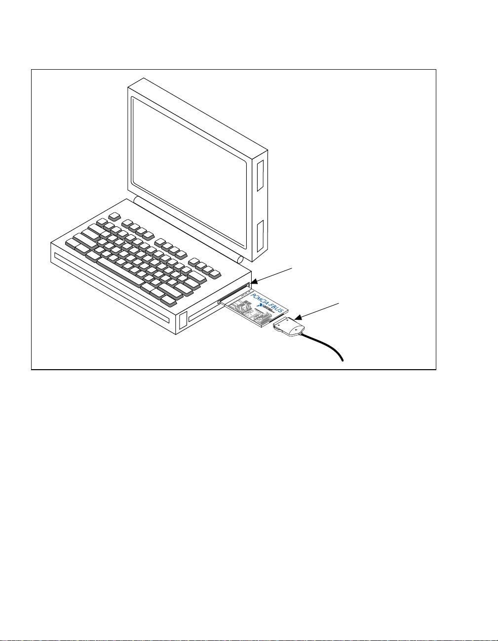
2. Insert the card into a free PC Card (PCMCIA) socket. The card has
no jumpers or switches to set. Figure 2-1 shows how to insert the
PCMCIA-FBUS and how to connect the PCMCIA-FBUS cable and
connector to the PCMCIA-FBUS card. However, the
PCMCIA-FBUS/2 card has two connectors. Refer to Appendix B,
Pinout Information, for more information about these two
connectors.
Chapter 2 Hardware Installation
PCMCIA-FBUS for Windows NT 2-2 © National Instruments Corporation
PCMCIA Socket
Portable
Computer
PCMCIA-FBUS Cable
Figure 2-1. Inserting the PCMCIA-FBUS
3. Connect the PCMCIA-FBUS to the fieldbus network.
One PCMCIA-FBUS cable is included in your kit. Refer to
Appendix B, Pinout Information, if you need to make a longer cable
than the PCMCIA-FBUS cable provided.
4. Power on your computer.
Now that you have installed and connected your PCMCIA-FBUS, you
are ready to install and configure the NI-FBUS software. Continue to the
next chapter, Software Installation and Configuration.
© National Instruments Corporation 3-1 PCMCIA-FBUS for Windows NT
Software Installation and
Configuration
3
Chapter
This chapter contains instructions on how to install and configure your
NI-FBUS software for Windows NT.
Evaluate the Default Settings
After you have installed the hardware, you are ready to install your
NI-FBUS software. However, you must evaluate the default settings for
your NI-FBUS software before you install the software. Table 3-1 shows
the default settings for the NI-FBUS software.
Table 3-1. NI-FBUS Software Default Settings
NI-FBUS Software Setting Default
Memory Base Address (hex) D0000
Interrupt Line (IRQ) 11
The NI-FBUS software default settings are suitable for most PCMCIA
systems. However, if these default settings conflict with another device in
your system, you must locate conflict-free resources.
To select conflict-free resources, you can use the Microsoft utility
Windows NT Diagnostics, which displays a list of the I/O port addresses,
interrupt levels, and DMA channels that are currently being used in your
system. Assign resources this utility does not list to your fieldbus
interface.
If you cannot find a free IRQ line, you can configure the PCMCIA-FBUS
card to operate in polled mode, without an IRQ line. In polled mode,
NI-FBUS polls your board periodically.

Chapter 3 Software Installation and Configuration
PCMCIA-FBUS for Windows NT 3-2 © National Instruments Corporation
Install the Software
Caution: If you reinstall the NI-FBUS software over an existing version, you lose
any existing board and port configuration information. Before you
reinstall the NI-FBUS software, write down your board configuration.
Also, if you changed any port configuration parameters from their
defaults, write down the new parameters.
Complete the following steps to run the software installation program for
either the NI-FBUS or NI-FBUS Configurator software:
1. Log in as Administrator or as a user that has Administrator
privileges.
2. Insert installation disk 1 into an unused drive.
3. In the Run... dialog box, type the following:
x
:\setup
where
x
is the letter of the drive containing the disk (usually aor b).
The interactive setup program takes you through the necessary steps
to install the software.
By default, the installation program installs the software into the
nifbus default directory. You can change this directory if you want
to install the NI-FBUS software into a different directory.
The installation program copies nifb.dll and drvintf.dll into
your Windows directory, and it copies the nifb.sys kernel mode
driver into the drivers directory. The installation program also
adds information to the Windows NT Registry.
After it copies the software components to the appropriate
directories, the installation program starts the NI-FBUS
Configuration utility. Proceed to the next section, Configure the
NI-FBUS Software.

Chapter 3 Software Installation and Configuration
© National Instruments Corporation 3-3 PCMCIA-FBUS for Windows NT
Configure the NI-FBUS Software
When you install the NI-FBUS software, the installation program starts
the NI-FBUS Configuration utility.
Configure the Base Address and IRQ
To add, view, or change your base I/O address or IRQ settings, complete
the following steps:
1. In the NI-FBUS Config window, select the icon of the board you
want to change and click on the Edit button. If you are adding a
board, click on the Add a Board button.
2. Choose PCMCIA as the Bus Type. The NI-FBUS Configuration
utility displays the default base address and IRQ line.
3. Change the default settings if they do not match the settings on your
board. Set the base address and IRQ line to the conflict-free
resources you found for your PCMCIA-FBUS.
If you want to configure your PCMCIA-FBUS to operate in polled
mode (without interrupts), select a valid IRQ line from the IRQ
drop-down list and check the Polled Mode checkbox. You must
enter a valid IRQ for the PCMCIA card in polled mode because of
the behavior of the Microsoft PCMCIA driver for Windows NT.
NI-FBUS does not actually use an interrupt line in polled mode, but
you still have to enter a valid IRQ.
4. Select the number of ports that matches your PCMCIA-FBUS. For
example, select 2 ports for the PCMCIA-FBUS/2.
Configure the Fieldbus Communication Parameters and Interface
Name You must assign a unique address and a unique physical device tag to
each of your fieldbus interfaces. Your interface must be at a fixed address
or a visitor address for you to start using NI-FBUS.
To assign addresses and tags using the NI-FBUS Configuration utility,
click on the port you want to edit, and click on the Edit button. The
NI-FBUS Configuration utility displays the default logical interface name
and some configuration information. Change these settings if necessary.

Chapter 3 Software Installation and Configuration
PCMCIA-FBUS for Windows NT 3-4 © National Instruments Corporation
If you want to assign a fixed address to your fieldbus interface, choose
Fixed Address and enter a value in the range 0x10 to 0xF7. If you want
your interface to be a temporary device that you do not intend to connect
to the fieldbus for an extended time, choose Visitor Address. If you want
a fieldbus network configuration utility to assign an address to your
interface over the fieldbus, choose Default Address.
Enter a unique tag at the Device Tag prompt. You may leave this empty
if you have set the address to Default Address and you want a fieldbus
network configuration utility to assign a tag over the fieldbus.
NI-FBUS assigns default values for other communication parameters.
Click on the Advanced button to view or change these parameters.
You do not have to reenter these configuration parameters every time you
power up your PC because NI-FBUS saves them. NI-FBUS also saves
changes made to these parameters over the fieldbus.
Configure the Link Active Schedule File
If you are using the NI-FBUS Configurator, you should not configure the
Link Active Schedule file; continue to the next section, Using the
NI-FBUS Configuration Utility after Installation. Or if you do not want
to do scheduling or use publishers and subscribers, continue to the next
section. If you want to do scheduling and use publishers and subscribers,
you must configure the Link Active Schedule file. Refer to Appendix A,
Configuring the Link Active Schedule File, in the NI-FBUS User Manual
for Windows NT, and then test the NI-FBUS software installation, as
described in the Test the Installation section later in this chapter.
Using the NI-FBUS Configuration Utility after Installation
You should use the NI-FBUS Configuration utility after installation in the
following cases:
• To add or remove a fieldbus interface
• To change the software settings to match your physical hardware
settings
• To view or change your software configuration settings

Chapter 3 Software Installation and Configuration
© National Instruments Corporation 3-5 PCMCIA-FBUS for Windows NT
The NI-FBUS Configuration utility (fbconf.exe) helps you to
configure the following information:
• Hardware information
– Number of boards
– Base address of each board
– IRQ line assigned to each board
• Logical name for each fieldbus interface (port); you can use this
information to access the port using the logical name
• Device Description (DD) information
– Base directory for DDs
– Location of the standard text dictionary
You need to change this DD information only if you use
NI-FBUS to communicate with devices that have
manufacturer-specific blocks or parameters, meaning that you
have device-manufacturer-supplied DDs.
• Fieldbus communication parameters for each fieldbus interface
To start the NI-FBUS Configuration utility, do one of the following:
• If you are using Windows NT 3.51, double-click on the fbconf icon,
which is part of the NI-FBUS program group, created in your
Program Manager during installation.
• If you are using Windows NT 4.0, select
Start»Programs»NI-FBUS»NI-FBUS Config.
• To use the command prompt, enter the command fbconf.exe to
start the NI-FBUS Configuration utility executable, which is located
in the utils subdirectory of your NI-FBUS installation directory.
Test the Installation
To make sure that your NI-FBUS software is installed correctly and is
working properly, complete the following steps:
1. After you configure your installation, restart Windows NT. You must
restart your computer before you can use the NI-FBUS software.
2. Start the kernel-mode device driver nifb by entering the following
command at the command prompt:
net start nifb
Table of contents
Other Fieldbus Specialists Computer Hardware manuals

Popular Computer Hardware manuals by other brands

ASROCK Rack
ASROCK Rack EP2C621D12 WS Quick installation guide

Renesas
Renesas M61323SP/FP Specifications

Agilent Technologies
Agilent Technologies G3588-68015 user manual

Pioneer
Pioneer DEQ-7200 owner's manual

Supero
Supero Supero BPN-SATA-933 BACKPLANE user guide

Renesas
Renesas Asynchronous SH7145F Application note


