A-Neuvideo ANI-4MV User manual

AUDIO / VIDEO MANUFACTURER
ANI-4MV
4x4 DVI/HDMI Quad Multi Video Wall Processer
INSTRUCTION MANUAL
A-NeuVideo.com
Frisco, Texas 75034
(317) 456-2461

SAFETY INFORMATION
1. To ensure the best results from this product, please read this manual and all other documentation before operating your equipment.
Retain all documentation for future reference.
2. Follow all instructions printed on unit chassis for proper operation.
3. To reduce the risk of re, do not spill water or other liquids into or on the unit, or operate the unit while standing in liquid.
4. Make sure power outlets conform to the power requirements listed on the back of the unit. Keep unit protected from rain, water and
excessive moisture.
5. Do not attempt to clean the unit with chemical solvents or aerosol cleaners, as this may damage the unit. Dust with a clean dry cloth.
6. Do not use the unit if the electrical power cord is frayed or broken. The power supply cords should be routed so that they are not
likely to be walked on or pinched by items placed upon or against them, paying particular attention to cords and plugs, convenience
receptacles, and the point where they exit from the appliance.
7. Do not force switched or external connections in any way. They should all connect easily, without needing to be forced.
8. Always operate the unit with the AC ground wire connected to the electrical system ground. Precautions should be taken so that the
means of grounding of a piece of equipment is not defeated.
9. AC voltage must be correct and the same as that printed on the rear of the unit. Damage caused by connection to improper AC
voltage is not covered by any warranty.
10. Turn power off and disconnect unit from AC current before making connections.
11. Never hold a power switch in the “ON” position.
12. This unit should be installed in a cool dry place, away from sources of excessive heat, vibration, dust, moisture and cold. Do not use
the unit near stoves, heat registers, radiators, or other heat producing devices.
13. Do not block fan intake or exhaust ports. Do not operate equipment on a surface or in an environment which may impede the normal
ow of air around the unit, such as a bed, rug, carpet, or completely enclosed rack. If the unit is used in an extremely dusty or smoky
environment, the unit should be periodically “blown free” of foreign dust and matter.
14. To reduce the risk of electric shock, do not remove the cover. There are no user serviceable parts inside. Refer all servicing to
qualied service personnel. There are no user serviceable parts inside.
15. When moving the unit, disconnect input ports rst, then remove the power cable; nally, disconnect the interconnecting cables to
other devices.
16. Do not drive the inputs with a signal level greater than that required to drive equipment to full output.
17. The equipment power cord should be unplugged from the outlet when left unused for a long period of time.
18. Save the carton and packing material even if the equipment has arrived in good condition. Should you ever need to ship the unit,
use only the original factory packing.
19. Service Information Equipment should be serviced by qualied service personnel when:
A. The power supply cord or the plug has been damaged.
B. Objects have fallen, or liquid has been spilled into the equipment.
C. The equipment has been exposed to rain.
D. The equipment does not appear to operate normally, or exhibits a marked change in performance.
E. The equipment has been dropped, or the enclosure damaged.
THIS SAFETY INFORMATION IS OF A GENERAL NATURE AND MAY BE SUPERSEDED BY INSTRUCTIONS CONTAINED WITHIN THIS MANUAL.

TABLE OF CONTENTS
ANEUVIDEO
1
CONTENTS
INTRODUCTION / PACKAGE CONTENTS / FACTORY RESET ...2
SPECIFICATIONS .........................................................................3
REAR PANEL & CONNECTION ....................................................4
REAR PANEL INTRODUCTION .................................................4
CONNECTION W/ RS-232 COMMUNICATION PORT .............4
CONNECTION W/ USB INTERFACE .........................................5
TWIST PAIR CONNECTION .......................................................5
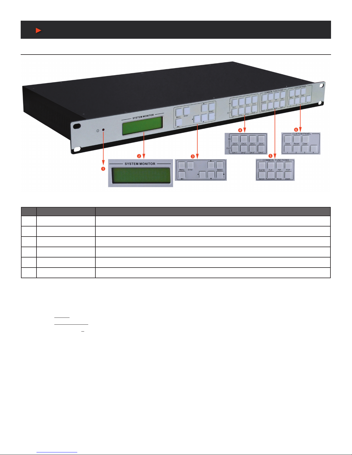
OPERATIONS OF THE FRONT CONTROL PANEL .....................6
FRONT PANEL INTRODUCTION ..............................................6
OP. OF THE MENU BUTTONS ...............................................7
OP. OF THE INPUT/OUTPUT SELECTION BUTTONS ...........7
OP. OF THE FUNCTION BUTTONS .........................................7
OP. OF CUSTOMIZED BUTTONS & THE NUMERIC KEYS .....7
MENU LEVELS INTRODUCTION .............................................8
OPERATION OF THE SOFTWARE .............................................10
INTRODUCTION OF THE SOFTWARE .................................10
INSTALLATION.........................................................................10
CONTROL CONNECTION ......................................................10
MENU BAR FUNCTION SETTINGS ..........................................11
FILE BUTTON ..........................................................................11
CONNECTION BUTTON .........................................................11
VIEW BUTTON ........................................................................11
HELP BUTTON ........................................................................11
MAIN FUNCTION SETTINGS ....................................................12
4X ZOOM-IN FUNCTION (VIDEO WALL) ...............................12
3X ZOOM-IN FUNCTION (VERTICAL VIDEO WALL) .............12
MATRIX SWITCHING FUNCTION .........................................12
PICTURE IN PICTURE (PIP) ..................................................13
PICTURE OUTSIDE PICTURE (POP) DISPLAYING ..............14
ADDITIONAL FUNCTION SETTINGS .......................................15
SETTINGS IN THE AUXILIARY FUNCTION AREA ..............15
ADVANCED FUNCTION SETTINGS ..........................................18
DISPLAY MODE SETTING ......................................................18
SHORTCUT BUTTON CUSTOMIZATION ...............................19
SYSTEM DIAGRAM ..................................................................20
DIAGRAM OF VIDEO WALL DISPLAY .....................................20
DIAGRAM OF MULTI-VIEWER DISPLAY ................................21
DIAGRAM OF FULL IMAGES DISPLAY ..................................22
FIRMWARE UPGRADE .............................................................23
Dear Customer
Thank you for purchasing this product. For optimum performance
and safety, please read these instructions carefully before
connecting, operating or adjusting this product. Please keep this
manual for future reference.
SAFETY PRECAUTIONS
Please read all instructions before attempting to unpack, install or
operate this equipment and before connecting the power supply.
Please keep the following in mind as you unpack and install this
equipment:
• Always follow basic safety precautions to reduce the risk of re,
electrical shock and injury to persons.
• To prevent re or shock hazard, do not expose the unit to rain,
moisture or install this product near water.
• Never spill liquid of any kind on or into this product.
• Never push an object of any kind into this product through any
openings or empty slots in the unit, as you may damage parts
inside the unit.
• Do not attach the power supply cabling to building surfaces.
• Use only the supplied power supply unit (PSU). Do not use the
PSU if it is damaged.
• Do not allow anything to rest on the power cabling or allow any
weight to be placed upon it or any person walk on it.
• To protect the unit from overheating, do not block any vents or
openings in the unit housing that provide ventilation and allow for
sufcient space for air to circulate around the unit.
DISCLAIMERS
The information in this manual has been carefully checked and
is believed to be accurate. We assume no responsibility for any
infringements of patents or other rights of third parties which may
result from its use.
We assume no responsibility for any inaccuracies that may be
contained in this document. We make no commitment to update or
to keep current the information contained in this document.
We reserve the right to make improvements to this document and/
or product at any time and without notice.
COPYRIGHT NOTICE
No part of this document may be reproduced, transmitted,
transcribed, stored in a retrieval system, or any of its part translated
into any language or computer le, in any form or by any means
— electronic, mechanical, magnetic, optical, chemical, manual, or
otherwise — without the express written permission and consent.
© Copyright 2016. All Rights Reserved.
Version 2.2 AUG 2016
TRADEMARK ACKNOWLEDGMENTS
All products or service names mentioned in this document may be
trademarks of the companies with which they are associated.

2
INTRODUCTION / PACKAGE CONTENTS
& factory reset
INTRODUCTION
The ANI-4MV is a powerful, universal and user-friendly image analyzing processor with (4) DVI Input ports and (4) Output ports. It is not
only a 4x4 matrix switcher, but also a multi-viewer video wall processor that supports PiP (Picture in a Picture), PoP (Picture outside a
Picture) and split screen display. Using the provided GUI interface, the location of the PiP and PoP can be placed anywhere on the display
simply by dragging and dropping the image.
As a video wall processor, any one of the input sources can be split to (4) horizontally mounted displays or to (3) vertically mounted
displays. The ANI-4MV has the capability to zoom-in on one image 3x or 4x (per output). The ANI-4MV can mix inputs with any combination
into (1) image, and then display that to any or to all the outputs. It also supports output resolution changes, contrast & brightness adjusting,
horizontal and vertical zooming and moving, and bezel adjustment.
The ANI-4MV offers various ways for system control through its RS-232 serial port, USB interface, and the TCP/IP network port. It can be
controlled easily by using the included control software ANI-4MVGUI.exe.
Applications include TV broadcasting, meeting room, network operations center, medical institutions, command & control center, etc.
This product has a 3 year warranty.
PACKAGE CONTENTS
• ANI-4MV
• RS-232 cable (4.4 ft/1.35M)
• Power Cord (North American)
• (4) Plastic Feet (for desktop use)
• Users Guide
FACTORY RESET
You can do a factory reset on the ANI-4MV with (2) methods.
1. On the front panel, select the “MENU“ button, you will nd “Factory Reset“ in the LCD, press the “Select” button to factory reset.
2. With the ANI-4MV GUI, open the software and connect to the switch. Click “View“, then “Factory Reset“ will show in drop-down list.
ANEUVIDEO

3
SPECIFICATIONS
Specifications
• Video Inputs: (4) DVI
• Input Connector: Female DB24+5
• Input Level: TMDS 2.9V/3.3V
• Input Impedance: 50Ω
• Video Outputs: (4) DVI
• Output Connector: Female DB24+5
• Output Level: TMDS 2.9V/3.3V
• Output Impedance: 50Ω
• Video Signal: DVI (or TMDS)
• Switching Speed: 200nS (Max)
• Video Bandwidth: 340MHz (6.75Gbit/s)
• Transport Delay: 5nS (±1nS)
• Crosstalk: <-50dB@5MHz
• Control: Front Panel Buttons, RS-232, TCP/IP, USB
• RS-232PinCongurations: 2=TX, 3=RX, 5=GND
• Control Software: ANI-4MVGUI.exe through USB, RS-232 or TCP/IP
• Power Supply: Internal: 100VAC ~ 240VAC, 50/60Hz
• Temperature: -20°F~+158°F (-20°C~+70°C)
• Power Cord Type: North American 18AWG power cord NEMA 5-15P to IEC-320-C13
• Humidity: 10% ~ 90%
• Power Consumption: 25W
• Dimension (WxHxD): 17.2 x 9.5 x 1.75 in
• Weight: 4.4 lb (Unit only) / 7.3 lb (Net)
As product improvements are continuous, specications are subject to change without notice.
ANEUVIDEO

4
Rear Panel & Connection
Rear Panel Introduction
Figure 1: ANI-4MV Interface Introduction
NO. NAME DESCRIPTION
1DVI INPUTS DVI-I connector, (4) input ports
2DVI OUTPUTS DVI-I connector, (4) output ports
3RS-232 9-pin female connector, for serial control
4USB USB interface, type B, for USB control and rmware updates
5TCP/IP TCP/IP network port. User controls the ANI-4MV with control software ANI-4MVGUI or direct commands
6AC100V~240V Duh!
Connection with RS-232 Communication Port
With the RS-232 port, the processing switcher can be controlled with the control software ANI-4MVGUI.exe. This RS-232 communication
port is a female 9-pin D connector. The denition of the pins are below.
NO PIN FUNCTION
1N/u Unused
2Tx Transmit
3Rx Receive
4N/u Unused
5Gnd Ground
6N/u Unused
7N/u Unused
8N/u Unused
9N/u Unused
Figure 2: 9HDF
ANEUVIDEO

5
Rear Panel & Connection
Please reference the following to connect.
1. Use a RS-232 cable to connect the COM port of the computer to the RS-232 connector of the ANI-4MV.
Figure 3: Connect with a PC
2. Run the control software and select the RS-232 connection.
3. If the connection is OK, then you can control the ANI-4MV.
Connection with USB Interface
By connecting the USB interface between the switcher and a computer, the user can control the ANI-4MV through the USB interface.
Before controlling, please install the USB driver by rst installing the control software ANI-4MVGUI.exe (as shown in Operations of the
Software). Plug and play and hot plug functions are supported by the USB interface of the ANI-4MV.
Twist Pair Connection
The ANI-4MV provides, via the TCP/IP communication port, user control by using the related communication software.
• ACTIVITY LED: The yellow LED always blinks when the network is working normally.
• LINK LED: The green LED stays on when the network is linked.
• RJ-45 PORT: RJ-45 communication port.
TIA/EIA T568A TIA/EIA T568B
PIN CABLE COLOR PIN CABLE COLOR
1green white 1orange white
2green 2orange
3orange white 3green white
4blue 4blue
5blue white 5blue white
6orange 6green
7brown white 7brown white
8brown 8brown
1st 4--5 1st 4--5
2nd 3--6 2nd 1--2
3rd 1--2 3rd 3--6
4th 7--8 4th 7--8
NOTICE: Cable connectors can use standard T568A or T568B, but they must be the same on both ends of one cable.
ANEUVIDEO

6
Operations of the
Front Control Panel
Front Panel Introduction
Figure 4: Front Panel Introduction
NO. NAME DESCRIPTION
qPower Indicator Turns on when the power is on (there is no power switch)
wLCD System monitor, to indicate the operation and real-time running state
eMenu Function Panel Function buttons required
rInput/Output Channels (4) Input and (4) Output channels
tFunction Pattern Panel Common functions for output image displaying effects
yCustom Panel Used for saving or recovering a customized setting
Note: Part r, tand yare the operation areas for shortcuts.
1. For the non-numeric buttons, you can use the menu buttons after you press any numeric button, or use the numeric buttons directly.
Example:
Press the MOVE button to enter into the menu for HP/VP settings.
Press the RESOLUTION button, it will show the corresponding menu.
Press numeric button 1 directly, then the resolution will be set to 1080p. (Without having to conrm entry)
2. For the numeric buttons (including the input/output selection buttons), it will show the corresponding menu when you press any of them,
also without having to conrm entry.
3. The priority of the buttons of different menu levels is shown in the Menu Levels Introduction.
The next pages have detailed introductions for every button.
ANEUVIDEO

7
Operations of the
Front Control Panel
Operations of the Menu Buttons
BUTTONS OPERATION DESCRIPTION
MENU Cycles thru the menu items in the same level. For Example: In the rst level of the menu between: Quarter, Full, PiP,
PoP, Factory Reset, SAVE, RECALL and CLEAR.
←Returns to the previous level of the menu.
ENTER Enters the sub-level of the menu. For Example: To enter to the second level of the menu “Resolution” from the rst
level of the menu “Full”.
SELECT Executes the selected operation.
< > Moves the on-screen cursor or adjusts the position of the image.
Increases or decreases the value of the parameter, such as channel or resolution etc.
Operations of the Input/output Selection Buttons
BUTTONS OPERATION DESCRIPTION
CH1 CH2 CH3 CH4 Selects the corresponding input channel.
CH1’ CH2’ CH3’ CH4’ Selects the corresponding output channel.
Note:
1. While it is in the 4x Full Screen Zoom-In and 3x Zoom-In function menu, selection of the input or the output channels are disabled,
except to set the resolution of the (4) output channels as a whole.
2. While in the PoP and PiP menu, the ability to select a single input channel or a single output channel is disabled.
Operations of the Function Buttons
BUTTONS FUNCTION DESCRIPTION
QUARTER 4x Full Zoom-In and 3x Zoom-In functions. (default display modes)
FULL Matrix switching displaying or distribution displaying. ((5) default modes in total)
PIP Picture in Picture (PiP) displaying. ((3) default modes in total)
POP Picture outside Picture (PoP) displaying. ((5) default modes in total)
SWITCH Selects the input or output channels, it is available together with the input or output channel buttons.
RESOLUTION Sets the output resolutions. Supports 1080p, 720p, WUXGA, UXGA, SXGA and XGA.
MOVE Adjusts the position of the image, used in conjunction with the direction buttons. (up, down, left and right)
ZOOM Sets the focus of the image to scale the image, used in conjunction with the direction buttons. (up, down, left and right)
Operations of the Customized Buttons and the Numeric keys
BUTTONS FUNCTION DESCRIPTION
SAVE Customized shortcut buttons of different menu levels and saved settings.
RECALL Customized menu recall button.
CLEAR Shortcut button, to clear the customized menu.
1, 2, 3, 4, Numeric buttons, to set the corresponding shortcut buttons for different menu levels.
Note: In the operational area of the shortcut buttons, when you press any button it will show the detailed information on the present menu
of the LCD screen.
ANEUVIDEO
>
>

8
Operations of the
Front Control Panel
Menu Levels Introduction
FIRST LEVEL INCLUDES: Quarter, Full, PiP, PoP, Factory Reset, SAVE, RECALL, and CLEAR.
SECOND LEVEL INCLUDES: Resolution, Set Position, Adjust Windows, Overlay, Board, Display, and Channel Switch.
THIRD LEVEL INCLUDES: Brightness, Contrast and CH’.
The relationship of each level of the menu is as shown below.
FIRST LEVEL SECOND LEVEL THIRD LEVEL
MENU Quarter
Type 1
MENU Resolution
1 1920x1080
MENU Color
MENU OUT 1 Brightness 0512
Contrast 100
MENU FULL Channel Switch
Type 1 IN 1 OUT 1
MENU Resolution
1 1920x1080
MENU Adjust Windows Fine tuning
MENU Channel 1 1HP
1HW
MENU 1VP
1VW
MENU Color
MENU OUT 1 Brightness 0512
Contrast 100
MENU PIP Channel Switch
Type 1 IN 1 OUT 1
MENU Resolution
1 1920X1080
MENU Set Position Position setting
MENU Channel 1 1HP 0001
1VP 0001
MENU 1HW 0001
1VW 0001
MENU Adjust Windows Fine tuning
MENU Channel 1 1HP
1HW
MENU 1VP
1VW
MENU Overlay
MENU OUT 1 CH1 CH2 CH3 CH4
1 2 3 4
MENU Board
ANEUVIDEO

9
Operations of the
Front Control Panel
FIRST LEVEL SECOND LEVEL THIRD LEVEL
MENU OUT ALL CH1 CH2 CH3 CH4
OFF OFF OFF OFF
MENU Display
MENU OUT 1 CH1 CH2 CH3 CH4
ON ON ON ON
MENU Color
MENU OUT 1 Brightness 0512
Contrast 100
MENU POP Channel Switch
Type 1 IN 1 OUT 1
MENU Resolution
1 1920x1080
MENU Set Position Position setting
MENU Channel 1 1HP 0001
1HP 0001
MENU 1HW 0001
1VW 0001
MENU Adjust Windows Fine tuning
MENU Channel 1 1HP
1HW
MENU 1VP
1VW
MENU Overlay
MENU OUT 1 CH1 CH2 CH3 CH4
1 2 3 4
MENU Board
MENU OUT ALL CH1 CH2 CH3 CH4
OFF OFF OFF OFF
MENU Display
MENU OUT 1 CH1 CH2 CH3 CH4
ON ON ON ON
MENU Color
MENU OUT 1 Brightness 0512
Contrast 100
MENU Factory Reset
MENU SAVE 1
MENU RECLL 1
MENU CLEAR 1
Note: In the rst column, MENU (in ORANGE) shows the rst row of the display, and MENU (in GREY)shows the second row.
ANEUVIDEO

10
Operation of the Software
Introduction of the Software
Installation
The ANI-4MV can be controlled by using the included software ANI-4MVGUI.
• INSTALLATION: Copy the software les to the controlling computer. To run the executable program, double click on the icon (or le
name) ANI-4MV GUI (shown in Figure 5).
• UNINSTALL: Delete all other software les.
Figure 5: ANI-4MV Control Software
Note: ANI-4MV_v1.1.30.exe is only used in its own given path.
Control connection
WAYS FOR SOFTWARE CONTROL: The ANI-4MV provides (3) ways to connect to the ANI-4MV, including the RS-232 serial port, USB
interface and TCP/IP network port.
SOFTWARE ACTIVATION: You can control the ANI-4MV if any of the connections are valid.
OPERATION: Click the CONNECTION button on the menu bar.
Figure 6: Popup Menu for Connection
RS-232: If connected successfully, the message window in the lower right corner of the main interface will show the message “Connection
Successful”. If not, a popup window will appear with the message “Can’t Open Com”.
USB: If not connected, a popup window will appear with the message “Can’t Find USB”. If connected, the message window will show
the message “Connection Success”.
TCP/IP: Using the network port, enter the IP address. The default IP address is 192.168.0.178, and the port number is 4001. The
message window will show the message “Connect NET Success”. This IP address can be changed if necessary.
DISCONNECT: To disconnect the current connection, Figure 7 shows the main interface and the available settings. The settings
mentioned below (Main Function Settings to Shortcut Button Customization) are referenced on the next page.
Figure 7: Main Interface
ANEUVIDEO

11
Operation of the Software
Menu Bar Function Settings
File Button
FUNCTION: To open a saved image display mode le, or to save a new one, or to save the current display mode le to another path.
DETAILED OPERATIONS: Run the control software and click on the menu button FILE. The sub menu item “Open” is to open a saved
image display mode le, and “Save” is to save the current image display mode le, and “Save as” is to save the current image display
mode le to another path. As shown in Figure 8.
Figure 8: File Menu
Connection Button
FUNCTION: Selects a connection method.
DETAILED OPERATIONS: As mentioned in “Control Connection”.
View Button
FUNCTION: To set the display modes and to reset the software.
DETAILED OPERATIONS: Click on the menu button VIEW, the sub menu item “Mode Setting” is to show the current display mode, for
more details please check “Shortcut Button Customization”.
WINDOW ADJUSTMENT: To auto adjust the window of the software to t the control computer.
FACTORY RESET: To clear the stored system information. It will display in 4x Full Screen Zoom-In mode.
Help Button
FUNCTION: Check the version of the software and the rmware of the ANI-4MV.
DETAILED OPERATIONS: Click the sub menu “About Soft Version” to check the version of the software or the rmware. As shown in
Figure 9.
Figure 9: Check the Software Version
ANEUVIDEO

12
Operation of the Software
Main Function Settings
The main function area of the control software includes 4x Full Screen Zoom-In, 3x Full Screen Zoom-In, Matrix Switching, PiP (Picture
in Picture), PoP (Picture outside Picture), output image switching function and customizable shortcut buttons. The detailed information is
shown in Figure 10.
Figure 10: Main Functional Area
Note: When in any one of the (5) modes (4x Full Screen Zoom-In, 3x Full Screen Zoom-In, Matrix Switching, PiP, PoP), please note the
following...
1. When in distribution or matrix switching display modes, you can set the resolution of any single output by checking the option box full
mode and also set as the total resolution. The ability to make these changes is disabled in the other (4) modes.
2. It is not able to set the correspondences between the inputs (channel input switch) and the (4) outputs.
3. It is not able to set the overlay hierarchical relationship of a single input channel or to set the hierarchical relationship of all input channels.
4. When in PiP or PoP display modes, it is able to set the output display state. The ability to make these changes is disabled in the other
(4) modes.
5. It is not able to move the image on the currently displayed image area on the software interface.
4x Zoom-in Function (Video Wall)
FUNCTION: To split a single input signal to (4) displays (Video Wall function), the input image is magnied by 4x, as shown in Figure 11.
DETAILED OPERATIONS: While the software is running, click on the button, the display mode area on the software interface will
show the output display mode of any one of the input channels. The (4) images on the menu make up a whole image, same as the input
image. The buttons are used for selecting the image from any one input channel.
3x Zoom-in Function (Vertical Video Wall)
FUNCTION: To split a single input signal to (3) displays, the image is rotated 90 degrees, and then to be displayed side-by-side (Video
Wall). Generally there will not be an output image on the rst output channel (the ANI-4MV shows a blue screen), and the images on the
second, third and fourth display are rotated 90 degrees to make up a whole image. As shown in Figure 12.
DETAILED OPERATIONS: While the software is running, click on the button, the display mode area on the software interface will
show the output display mode of any one of the input channels. The (4) images on the menu make up a whole image same to the input
image. The buttons are used for selecting the image of any one input channel.
Matrix Switching Function
FUNCTION: To choose one or all of the input images of the available (4) input channels and then output to the (4) output displays. As
shown in Figure 13. Choose the icon.
DETAILED OPERATIONS: Click on the button, the display mode area on the software interface will show the output display mode
of any one of the input channels. The image of each display is the same as the corresponding input image. Click on the button, the
display mode area on the software interface will show the output display mode of only one of the input channels. The output images are
the same for each display as shown in Figure 14.
ANEUVIDEO

13
Operation of the Software
Picture in Picture (PiP)
FUNCTION: The ANI-4MV is able to present all the input images of the (4) available sources on a single screen. It means that while the
screen is showing the main video, any of the other (3) input images can also be shown on the display. While there are pre-sets for the
image location, you are free to locate ANY image to ANY location by simply dragging one image to a new location. When you release the
mouse button, the ANI-4MV will update the image location.
DETAILED OPERATIONS: Click on the buttons, the display mode area on the software
interface will show the display effect of all the (4) input channels. The images (at most (3) are complete) on any one display are made
by the (4) input images. The buttons are used to select the output image of any one channel. The display
effects are shown in Figure 15 to 19.
ANEUVIDEO
Figure 15: First PiP Display Option
Figure 17: Third PiP Display Option
Figure 19: Second PiP Display Option
Figure 16: Second PiP Display Option
Figure 18: First PiP Display Option

14
Operation of the Software
Picture outside Picture (POP) Displaying
FUNCTION: To show the output images of different channels on a single screen. It means that while the screen is showing the frame of
the main video, any of the other (3) input images can also be shown on this screen, but located beside the main image.
DETAILED OPERATIONS: Click on the buttons, the display mode area on the software interface will show the
effect of all (4) input channels. The images on any output channels are made by the (4) input images. The
buttons are used for checking the output image of any one channel. The effects are shown in Figure 20 to 22.
Figure 20: First PoP Display Option
Figure 21: Second PoP Display Option
Figure 22: Third PoP Display Option
ANEUVIDEO

15
Operation of the Software
Additional Function Settings
Settings in the Auxiliary Function Area
FIRST AUXILIARY FUNCTION AREA: In this area users can set the contrast, brightness and add or remove the border for the output
images. As shown in Figure 23.
Figure 23: First Auxiliary Function Area
CONTRAST/BRIGHTNESS SETTING: To change settings to the images contrast/brightness for a single channel or all channels, select
the corresponding radio button and drag the bar to an appropriate position. Then press the SET button to conrm. In this area, the RESET
button is used to set the value of contrast/brightness back to the factory default (Default value of image Contrast: 100, Brightness: 512).
BORDER SETTING: To set the border of an image for a single channel or all channels, select the corresponding check box and press
the SET button to conrm your operation. The OFF/ON button is used to enable or disable the display border of the input images for all
channels.
SECOND AUXILIARY FUNCTION AREA: In this area, users can set the image position and zoom. As shown in Figure 24.
Figure 24: Second Auxiliary Function Area
IMAGE POSITION SETTING: To move the position of the output image for any single channel, select the corresponding radio button and
use the directional buttons UP, DOWN, LEFT and RIGHT to the appropriate position.
IMAGE ZOOM IN/OUT: To zoom in/out in both horizontal and vertical directions. The buttons HZoomIn and HZoomOut are for adjusting
the horizontal direction. And VZoomIn and VZoomOut are for adjusting the vertical direction.
Note:
1. The image begins to zoom in/out from the top left corner, and extends to a xed maximum size, whenever you drag the mouse or set the values.
2. Image zoom setting is available only in Full Displaying mode.
ANEUVIDEO

16
Operation of the Software
THIRD AUXILIARY FUNCTION AREA: In this area, users can set the bezel size for the adjacent images in zoom-in mode, to make the
whole image look cohesive. As shown in Figure 25.
Figure 25: Third Auxiliary Function Area
When in 3x Zoom-In mode and 4x Zoom-In mode, press the GET button to get the bezel information of the image. Enter a new value and
press the SET button to conrm. Figure 26 and Figure 27 will show you the difference between the original image and the adjusted image.
Note:
1. Bezel size setting is mainly used when there is an offset between the images on the displays.
2. In Figure 26, the position of the images on the left side is lower than the right ones. The places marked with circle show the effect where
the images are joined (before & after).
Figure 26: Original Image Figure 27: Adjusted Image
RESOLUTION SETTING: The ANI-4MV supports various resolutions, such as 1080p (1920x1080), 720p (1280x720), WUXGA
(1900x1200), UXGA (1600x1200), SXGA (1280x1024) and XGA (1024x768). The selection panel is at the left bottom corner of the main
interface. As shown in Figure 28.
Figure 28: Resolution Setting
In Full Displaying mode, you have the ability to change the output resolution respectively. In other modes, the resolution of all outputs only
can be set as a whole. Select the check box “Full Mode” to set the resolution for a single channel, and deselect this check box to set the
resolution for all channels as a whole. Then press the SET button to conrm. The default resolution is 1080p (1920x1080).
ANEUVIDEO

17
Operation of the Software
INPUT CHANNEL SETTING: The ANI-4MV allows for assigning (1) input image to (1) output channel (not the physical output interface
connected with the display). The selection panel is at the bottom of the main interface, as shown in Figure 29.
Figure 29: Channel Input Selection
OVERLAY HIERARCHICAL RELATIONSHIP SETTING: The Overlay Hierarchical setting for the ANI-4MV is applied for the PiP display
mode. In the following picture Figure 30, L1 (Level 1) is the bottom layer, and L4 (Level 4) is the top layer. The radio button ALL affects
all channels and DIFFERENT is for setting a single channel.
Figure 30: Overlay Hierarchical Relationship Setting
OUTPUT DISPLAY ON/OFF: Used to turn Off and On the display with the output image of (1) channel. Select the check boxes and press
the SET button to conrm. As shown in Figure 31.
Figure 31: Output Display On/Off
COMMUNICATION INFORMATION: This area is to check the connection status between the computer and the ANI-4MV. (Shown in
Figure 32) Detailed information is shown on the right side of the box.
Note: If the adjusting image does not synchronize with the output images shown on the displays, please press the button.
Figure 32: Additional Function Setting
ANEUVIDEO

18
Operation of the Software
Advanced Function Settings
Display Mode Setting
This function allows for saving or loading display modes. Right-click in any area on the main interface (except the menu area) or press
VIEW on the main bar, there will be (4) items about modes shown on the popup menu, Figure 34.
Figure 34: Popup Menu
Among them, the “Load” mode is to load a saved or default display mode le (switch to another display mode). The “Save” mode is to
save the present mode as a new one, which is modied from a default mode. Figure 35 will show you the “Load” mode page.
Figure 35: Load Mode Page
The corresponding display mode to each number is shown in the following table.
Note: The number is just a code name for the corresponding display mode, and it can be modied to a new name, which is easier to
remember. Users can change the name in the “Mode Settings” by pressing the SET NAME button to rename it. There is no limitation to
the name (Name repetition, long name and special characters are available).
ANEUVIDEO
Table of contents
Other A-Neuvideo Computer Hardware manuals