CONTENT
PACs
V1
Gig2
wae
ternonacsnyacticwenvenaeitacceaeesbecee
eos
oeeanoned,
3
Dear
CuUSIOMEN
6
acetntts
ernie
4
PIECAUTION
S
estuncetese
is
Ane
eee
ee
5
COANECHING
ANS
UNIS:
siirdacassiclessccesessezavaencnseebieieie
5
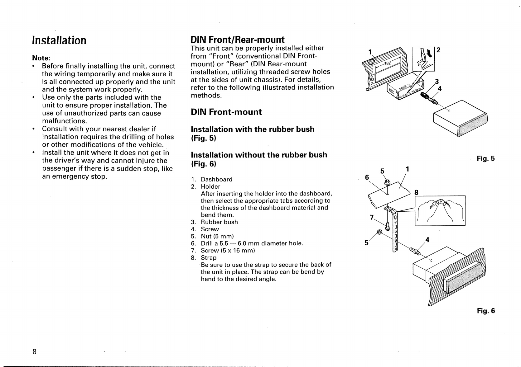
IFYSTANAUION
ies
tieees
covert
onaciinteteas
eerie
iaictata
8
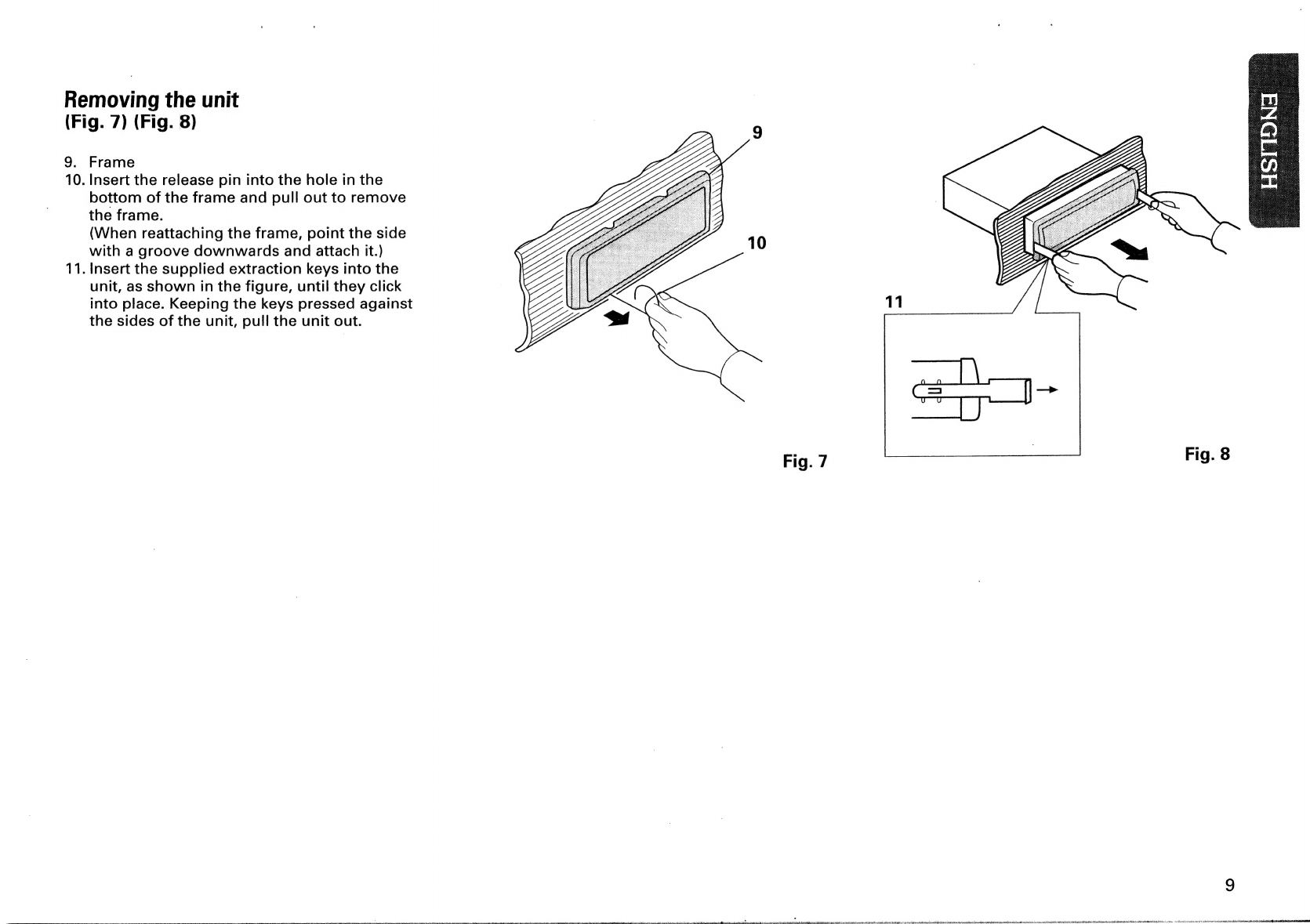
Using
the
Clear
ButtOn’
asin
sAieiew
ct
esiicccese!
11
Changing
the
Spectrum
Analyzer
Display
........
11
Setting
the
Head
Unit
..........
cc
ceeeceeeeeeeeeeeeneeeeaee
12
Adjusting
the
VolUMme
..........:cccceeesenseeeeeeeeeeeeeeenees
13
Adjusting
the
Listening
Position
...............cee
13
Adjusting
the
Equalizer
Curve
...........ccccccceeeeeeees
15
Sound
Field
Control
Function
......
sLetadantrusueioneeee
19
Using
the
Remote
Control
..........c.cceceeeeseeeeeeeeeneee
20
SPECINICATIONS
oiamiucuiinisiirealexs
eerie
heat
aantenanncyes
21
=P
SS
RE
SAN
NES
ERPS
VR
DE
EIT
ES
LSI
BIT
ACS
EP
SEES
REESE
NIU
TER
LIES
SELLE
IRI
ENE
DELILE
EIEL
EELS
L
ELE
ALLIEN
ALE
ELLE
LO
ELLIE
OLE
ELE
EL
RO
EE
RTE
ET
RE
EE
np
En
denne
ESE
ES
nn
nS
StF
PR
EE
ea
tee
ee
Eas
OS
Se
Te
Se
OE
ET
IER
Serer
OE
EEE
Te
OE
eS
Te
RE
Ee
Te
ARS
EE
IR
ER
EE
TT
Re
I
FE
CEN
Se
Se
OL
OS
Ee
Se
EP
CE
ee
ETE
ee
SE
TABLE
DES
MATIERES
ale
Pes
Oa
a
[9
pe
gee
meme
ner
reer
mehr
orrreneneee
cre
etc
3
ChE
CHEAE
sccdidesisandeeet
aed
22
PRECAUTIONS
cies
Gicceieieieeaasas
23
Connexion
deS
apparels
..........c:ccesesesesesseeeeeeeeees
23
InStallauOM
siniisietenenantwadecineaen
Aikiesemtes
26
Utilisation
du
bouton
de
rearmement
...............
29
Modification
de
l’afficheur
de
'analySeur
d@
SPECtIre
.........ccccccseeeeeeeeeeeeeeneneees
29
Réglage
de
Il’élément
Central
.............ccseeeeeeeeeeees
30
Réglage
du
niveau
d’6COUTE
......eeeeeee
cent
eee
31
Réglage
de
la
position
d’eCOute
..............:eeeee
31
Réglage
de
la
courbe
d’égalisation...............08
33
Commande
du
Champ
SONOFSE
..........::cccceeeeeeeeenes
37
Emploi
de
la
tél6commande
.............:::cesseeeeeeeeees
38
SPECINCALIONS
sicncssincctivetnecmveseaaewetanteineiteeenes
39