Fieldmaster SABRE 1200 Owner's manual

SABRE 1200 / 1500
ROTARY SLASHER / TOPPER
Models: SABRE
OWNERS/OPERATORS MANUAL
AND SPARE PARTS LIST

This manual contains valuable information about your Fieldmaster mower. It has been
carefully prepared to give you helpful suggestions for operating, adjusting, servicing
repair parts.
Keep this manual in a convenient place for quick and easy reference. Study it carefully.
You have purchased a dependable and sturdy implement, but only by proper care and
operation can you expect to get the service and long life designed and built into it.
RIGHT-HAND AND LEFT-HAND sides are determined by watching from the tractor side.
Sometime in the future, your implement may need new parts to replace those are worn or
broken. If so, go to nearest Fieldmaster dealer and provide them with the model and part
number.
Congratulations for purchasing your new Fieldmaster implement.
This implement has been designed and manufactured following all safety and quality
requirements needed for a safe and satisfactory use over time.
A careful reading of this manual will allow you to understand this new piece of equipment
and will provide you all the tools needed to use it safely.
Proper maintenance and knowledge of the safety rules of use will ensure the best
performance and extend the life of the machine.
The Safety Alert Symbol used throughout this manual and on safety decals of the
machine indicates the presence of potential hazard to the operator. When you see this
symbol, be alert and carefully read the message that follows it.
The Safety Alert Symbol is used in conjunction with following Signal Words, according to
the degree of possible injuries that may result operating the implement:
DANGER
Indicates an imminently hazardous situation that, if not avoided, will result in death or
serious injury.
WARNING
Indicates a potentially hazardous situation that, if not avoided, could result in death or
serious injury, and includes hazards that are exposed when guards are removed. It may
also be used to alert against unsafe practices.
CAUTION
Indicates a potentially hazardous situation that, if not avoided, may result in minor or
moderate injury. It may also be used to alert against unsafe practices.

IMPORTANT
Indicates instructions or procedures that, if not observed, can cause damage to
equipment or environment.
NOTE
Indicates helpful information.
READ, UNDERSTAND, and FOLLOW the safety messages following the Safety Alert
Symbol and Signal Words. Failure to comply with safety messages could result in serious
bodily injury or death.
1.
ABOUT THIS MANUAL
The operator must read the manual for a correct understanding of the hazards that may
present when operating the implement, as well as for obtaining optimum performance
from the machine.
The manual is part of the machine, it must be kept in good condition and remain with the
machine even in case of resale, until its demolition. In case of loss or damage, request a
new copy from the Manufacturer, Importer or your Dealer.
The information, descriptions and illustrations in this manual describe the state of the
product at the time of its publication, and may not reflect the product in the future.
The Manufacturer reserve the right to make design improvements or changes in
specifications without incurring any obligation to install them on units previously sold.
Text, illustrations and drawings of this manual cannot be disclosed or transmitted, in
whole or in part, to third parties without the written permission of the Manufacturer. All
rights are reserved
SAFETY
Safety is a primary concern in the design and manufacturing of our products. Unfortunately,
our efforts to provide safe equipment can be wiped out by a single careless act of an
operator.
In addition to the design and configuration of equipment, hazard control and accident
prevention are dependent upon the awareness, concern, prudence and proper training of
personnel involved in the operation, transport, maintenance and storage of equipment.
It has been said, “The best safety device is an informed careful operator.” We ask you to be
that kind of operator.
The manufacturer assumes no liability for any damage resulting from not applying the
behavioral rules indicated in the manual.

1.1.
GENERAL SAFETY INSTRUCTION
DANGER
The machine must be used only by authorized and well-trained operators. The operator
must have read and understood the instructions of this manual. They must make adequate
preparation for the proper use of the machine and in case of doubt about the use of the
machine and/or the interpretation of this manual the operator must contact the
Manufacturer or the Dealer immediately.
WARNING
The manual must always remain with the machine. In case of loss or damage, request a
new copy from the Manufacturer or your Dealer.
WARNING
Follow strictly the rules prescribed by the safety pictograms applied to the machine.
WARNING
Be sure that all safety pictograms are legible. If pictograms are worn, they must be replaced
with others obtained from the Manufacturer and placed in the position indicated by this
manual.
DANGER
Before using the machine, make sure that all safety devices are installed and in good
working conditions. In case of damages of shields, replace them immediately.
DANGER
Is absolutely forbidden to remove or alter safety devices.
DANGER
Before starting and during operation of the implement make sure there are no people or
animals in the area of operation: the machine can project material from the back, front or
side, with risks of serious injury or death.
DANGER
Pay maximum attention to avoid any accidental contact with rotating parts of the machine.
DANGER
During operation, adjustment, maintenance, repairing or transportation of the machine, the
operator must always use appropriate Personal Protective Equipment (PPE).

•Ahard hat
•Protective shoes with slip resistant soles
•Protective goggles, glasses or face shield
•Heavy gloves
•Protective clothing
•Hair net or similar to contain long hair
•Suitable ear protection (ear muffs, ear plugs)
DANGER
Do not operate the implement while wearing loose-fitting clothing that can give rise to
entanglement in parts of the machine.
DANGER
Do not operate the implement when tired, not in good condition or under the influence of
alcohol or drugs.
CAUTION
If the use of the machine is required at night or in conditions of reduced visibility, use the
lighting system of the tractor and possibly an auxiliary lighting system.
1.2.
EQUIPMENT SAFETY INSTRUCTIONS
WARNING
Use the implement for its intended purpose only. Improper use can damage the implement
and cause serious injury to persons, animals, or death.
DANGER
The machine should be used by a single operator driving the tractor.
WARNING
Any unauthorized modification of the machine may cause problems in safety and relieves
the Manufacturer from any liability for damages or injuries that may result in operators, third
parties and objects.
WARNING
Before using the machine, familiarize yourself with its controls and its working capacity.
WARNING
Do not leave the implement unattended with tractor engine running.
This includes but is not limited to the following -

WARNING
Do not operate implement on unstable (muddy or sandy) or rocky ground.
WARNING
Keep the machine clean from debris and foreign objects which may damage functioning or
cause injury.
WARNING
Do not use the machine if the category of the connecting pins of the implement does not
match that of the tractor hitch system.
WARNING
Do not use the machine with missing bolts, screws, pins, safety guards or safety pins.
WARNING
Never use the machine to transport or lift people, animals or objects
WARNING
Make certain that at least 20% of the total weight (tractor, implement and ballast) is on the
front axle of the tractor to ensure stability. Add front ballast if required.
WARNING
Before engaging the tractor PTO, make sure the tractor PTO speed is set as required for
this implement (540 rpm or 1000rpm). Do not over speed PTO or machine breakage may
result.
DANGER
Do not operate the implement if the driveshaft is damaged. The driveshaft could break
during operation, causing serious injury or death. Remove the driveshaft and repair or
replace it before continuing operation.
1.3.
OPERATING SAFETY INSTRUCTIONS
WARNING
Before using the machine, be sure to have cleared the operating area from obstacles
(stones, branches, debris, etc...). Mark all the obstacles that cannot be removed (e.g. by
means flags).

DANGER
Never engage the tractor PTO in the presence of people close to the driveshaft. The body,
hair or clothing of a person can get caught in rotating parts, causing serious injury or death.
DANGER
Before engaging the PTO and during all operations, make sure that no person or animal is
in the immediate area of action of the machine. Never use the implement if people are in
the working area.
DANGER
It's absolutely forbidden to stand near an implement like this when parts are moving.
WARNING
The operator must operate implement (lifting/lowering) only from the driving seat of the
tractor. Do not perform lifting maneuvers on the side or behind the tractor.
WARNING
Before making changes in direction, turns or going in reverse, slightly lift the implement off
the ground after disengaging the power take-off, to avoid damage to the machine.
DANGER
In presence of steep slopes the action of this machine may cause instability of the tractor
with a risk of tipping off which a consequence may be serious injury or death hazard.
Consult the manual for the tractor to determine the maximum slope that the tractor is able
to deal with.
DANGER
Always disengage the PTO before raising the implement and never engage the PTO with
the implement raised. The machine might throw objects at high speed, causing serious
injury or death.
WARNING
Never leave the driver's seat when the tractor is turned on. Before leaving the tractor, lower
the implement to the ground, disengage the PTO, insert the parking brake, stop the engine
and remove the key from the control panel.
DANGER
The PTO shields of the tractor and implement side, the driveshaft shielding and the
driveshaft retaining chains must be properly installed and in good condition, to avoid the
risk of entanglement with serious injury or death.

DANGER
Before engaging the PTO of the tractor, always make sure that the drive shaft is mounted in
the correct direction, and that its clamping elements are properly connected both to tractor
side and to Rotary Hoe side.
WARNING
Stop operating immediately if blades strike a foreign object. Repair all damage and make
certain rotor, blades, couplings, PTO shaft and bolts are in good condition before resuming
operation.
WARNING
Always disengage the tractor PTO when the driveshaft exceed an angle of 10 degrees up or
down while operating. An excessive angle with driveshaft rotating can break the driveshaft
and cause flying projectiles.
CAUTION
Avoid clutch overheating and wearing caused by too long or frequent slipping of the clutch,
since it can damage the clutch components. Before checking the clutch, make sure it has
cooled. Clutch could be extremely hot and cause a severe burn.
CAUTION
Prolonged use of the implement can cause overheating of the gearbox. Do not touch the
gearbox during use and immediately after, it could be extremely hot and cause a severe
burn.
WARNING
All repairs to the implement must be performed by qualified and trained operators, with the
tractor engine off, the PTO disengaged, the implement lowered to the ground or on security
stands, the ignition key off and the parking brake set.
1.4.
TRANSPORTING SAFETY INSTRUCTIONS
WARNING
Before transporting, determine the stopping characteristics of the tractor and implement.
WARNING
Transport only at speeds where you can maintain control of the equipment.
WARNING

When driving on roads, the implement must be in transport position,adequately raised
from the road surface, with tractor lifting hydraulics locked so that the implement cannot
be lowered accidentally.
DANGER
The implement may be wider than the tractor. Pay attention to transporting for people,
animals, buildings/sheds and/or other obstacles.
WARNING
When turning, use extreme care and reduce tractor speed.
WARNING
Do not operate the tractor with weak or faulty brakes or worn tires.
CAUTION
Always use tractor lighting system and auxiliary lighting system for an adequate warning to
operators of other vehicles, especially when transporting at night or in conditions of
reduced visibility.
DANGER
In the case of lifting this implement, make sure that any lifting device is suitable to perform
the operation safely, and use only the lifting points prescribed on Rotary Hoe.
1.5.
MAINTENANCE SAFETY INSTRUCTIONS
WARNING
All maintenance and repair operations must be performed by qualified and trained
operators, with the tractor engine off, the PTO disengaged, the implement lowered to the
ground or on security stands, the ignition key off and the parking brake set.
WARNING
Perform repairs and replacements part should only be original spare parts provided by the
manufacturer, importer or your dealer.
DANGER
Perform maintenance operations using appropriate Personal Protective Equipment
(protective eyeglasses, hard hat, hearing protection, safety shoes, overall and work gloves,
filter mask).
CAUTION

Before any maintenance operation, make sure that the parts which become hot during use
(friction clutch, gearbox...) have cooled.
WARNING
Do not perform repairs that you do not know. Always follow the manual instructions and in
case of doubt contact the Manufacturer or your dealer.
DANGER
Do not swallow fuels or lubricants. In case of accidental contact with eyes, rinse well with
water and consult a doctor.
1.6.
STORAGE SAFETY INSTRUCTIONS
WARNING
Never leave the tractor unattended with the implement in the lifted position. Accidental
operation of lifting lever or a hydraulic failure may cause a sudden drop of the unit which
may result in injury/death.
DANGER
Following the operation, or before unhooking the implement, stop the tractor, set the
brakes, disengage the PTO, lower the attached implement to the ground, shut off the
engine, remove the ignition key and wait for all moving parts to stop.
WARNING
Make sure all parked machines are on a hard, level surface and engage all safety devices.
CAUTION
Place support blocks under implement as needed to prevent the unit from tipping over onto
a child and/or an adult. An implement that tips over can result in injury or death.
CAUTION
Store the unit in an area away from human activity.
1. SAFETY LABELS
The safety labels applied on the machine give fundamental information for using the
machine safely.
Make sure safety labels are in good conditions. If pictograms are worn, they must be
replaced with others obtained from the manufacturer and placed in the position indicated
by this manual.

Make sure the safety labels are legible. If necessary, wipe them by a cloth, with soap and
water.
5.1. STARTUP
Before the startup and before each use, perform the following pre-operation inspections
and service of the implement:
• Check that the implement has no damaged functional parts and has all mechanical
parts are good condition. Repair and / or replace the damaged parts;
• check that the implement has no missing parts (pins, safety pins, plugs oil ...).
Restore the missing parts;
• check that all guards and safety devices have no damages and are properly
positioned. Repair and / or replace the damaged shields, restore the correct position;
• verify that the PTO driveshaft is properly installed (see section: Connection of the
drive shaft);
• check that the driveshaft clutch is in good condition, and that its components are
not subject to "sticking" (see section: Maintenance / Driveline);
• check the presence of lubricant in all greasing points of the implement (driveshaft,
supports...)
• Check for oil leaks from the gearbox or the transmission side cover. Identify the
reason of loss, then repair and / or replace the damaged components;
• check the correct oil level in the gearboxes
• check that blades are not excessively worn and the relating hardware is correctly
tightened
• check that all hardware (nuts, bolts, etc.) are properly tightened.
• check that all safety decals are correctly positioned, in good condition and legible.
Replace any damaged decals;
• check that there is no constraints that may prevent the movement of equipment.
Remove any constraint.
Before the startup and before each use, make the following checks on the operating area
you intend to operate:
• check that area is clear of foreign objects (rocks, branches or debris). Remove any
obstacle and visibly highlight obstacles that cannot be removed (e.g. with flags);
• make sure that in the area you intend to operate there are no people or animals;
• make sure the soil to be worked is not too grassy, muddy, sandy or rocky.
WARNING
Before conducting the above inspections and service, make sure the tractor engine is off,
all rotation parts are completely stopped and the tractor is in park with the parking brake

engaged. Make sure the implement is resting on the ground or securely blocked up and the
tractor lifting hydraulics locked.
Once all the checks above have been done, start the tractor and the implement as follows:
•start the tractor and engage the tractor PTO at low rpm, making sure that the
implement is NOT in the raised position but close to the ground, then increase speed
engine until to 540 or 1000 rpm (dependent on which size model you have purchased)
•lower the implement on the ground and simultaneously start driving the tractor
forward at low speed. Subsequently, increase the ground speed depending on ground
conditions;
•If the outside temperature is very cold, it's recommended to engage the PTO and
have the implement operate at low speed (with the tractor stationary) to warm oil and
lubricate parts;
•Drive for a while operating the implement then stop the tractor to check the quality
of the work performed. If you need to get off the tractor, reduce engine speed and
disengage PTO, set the parking brake, stop engine and remove the ignition key.

Introduction
Your Sabre Slasher has been designed to do a range of work to your satisfaction. This
list of instructions covers the basic requirements for maintenance and will ensure good
service if carried out.
Cautionary Advice
Special safety features are incorporated in the design of this machine for your
protection but careless operation can still cause damage or injury.
DON’T let familiarity trap you into danger.
DON’T attempt to clear away any obstruction whatever while the machine is operating
or spinning to a stop.
KEEP WELL AWAY from machine if cutter is spinning.
SPECTATORS (particularly children) must be kept well away while machine is
operating as sticks and stones can fly further than thought.
MAKE REGULAR INSPECTION of the cutter assembly for fracture and be sure that
ails and ail plate are securely attached. Replace if any irregularily or excessive wear
shows.
Fitting to the Tractor
The mower is attached to the tractor three point linkage in normal manner. The
telescopic drive shaft can then be fitted.
Fit stabiliser bars or chain.
Fit the drive shaft securely to the tractor P.T.O. and gearbox input shaft. Ensure that
both splined yokes are securely fastened to the splined shaft on both the tractor and
the mower.
See notes on drive shaft.
Important Notes
CORRECT SET-UP OF ‘FLOATING TOP LINK’ SLOT / CONNECTION TO TRACTOR:
1) Once the machine is connected to the tractor, set the tractor and machine down
on at ground (preferably concrete)
2) Lift the lower link arms slightly to just take the weight of the front of the machine
(i.e. the front of the skids would be 5mm off the ground). If machine tted with
front wheels or rollers these should be set to just run on the ground.
3) Set the lower link draft arms of the tractor at this position so they cannot go lower
than this, and ensure they can oat. (I.e. not xed)
!
CAUTION

4) At this point, set the top link into the centre of the top link slot (not the hole)
5) Ensure the xed top link hole is only ever used during transport of the machine.
Following this correct procedure will ensure:
-A good even cutting nish
-Reduce the possibility of scalping or digging in
-Extended wearing life of the side skids
-Machine construction is relieved of undue stresses
Failure to set up as above can result in serious damage to the machine caused by
tractor weight transferring to headstock and chassis which is NOT covered by the
warranty.
Before commencing work you will want to adjust the height of the cut. With your
FIELDMASTER SABRE Series there are numerous cutting heights to achieve the
optimum desired length of cut to prevent scalping and give an even and accurate cut.
N.B. Machine is designed / factory set with correct ‘lean-in’ angle (blade tip lower at
front than rear)for efcient cutting and discharge.
Simple adjustment is carried out by removing the bolts on the side of the skids and
relocating them once the skids have been raised or lowered.
There are three basic ways to adjust the height of the cut:
1) By adjusting the skids in relation to mowing deck;
2) By adjusting the rear roller or wheels in relation to the mowing deck and skids; (if
tted)
3) By adjusting both the roller assembly or wheels separately (if tted) in relation to
the mowing deck to give a wide range of roller-to-skids positioning in conjunction
with altering the height of cut.
It is important to set your FIELDMASTER SABRE up correctly for mowing according to
the ground conditions.
Firstly, in the optimum flat field mowing the FlELDMASTER should be used on the
roller only with the skids approximately one inch higher above the roller to give
stability on any slight unevenness and to avoid any undue lateral roll of the machine at
higher speeds.
Secondly, where mowing conditions are not ideal, it is important that the skids are set
at approximately the same height as the roller when fitted.
Thirdly, in more extreme undulations and rougher ground it is best to have the roller
(where tted) about one inch above the skids.
These three setting positions for three different types of mowing applications have
proved to be the most satisfactory.
There are other points which could be mentioned, such as wet conditions where it’s
important that the roller takes most of the weight of the machine rather than the skid to

avoid skid marks and also in very dry conditions if the ground is reasonable skid wear
can be reduced with more pressure on the roller. However, individual conditions and
varying operators will nd success sometimes in the varying of these conditions.
A ner adjustment can be achieved by lengthening or shortening the tractor top link
arm.
It is important that the top link arm is adjusted so that the skid runners are running
parallel with the ground. This will automatically give the mowing deck approximately
3/4” (19mm) ‘lead-in’ required for good mowing. This check should be made with
tractor and mower on level surfaces with mower in cutting position.
The best cutting performance will be gained when operating at 540 RPM is
maintained.
The Telescopic Drive Shaft
There is a wide range of tractors and the horizontal distance between the power take
off shaft and the drawbar varies considerably. A specific instruction for each would
require extensive research. However, taking for example the minimum and maximum
conditions, safe working lengths of the drive shaft are as follows:
Once the shaft is fitted to the machine or tractor a simple test should be carried out.
On raising and lowering the machine fully on the linkage arm, at no point of time
should the P.T.O. shaft be fully compressed. During the raise and lowering travel,
when the P.T.O. shaft is at the shortest length, allowance should be made for the shaft
to compress a further 40mm, but taking care that the shaft is not cut too short so that
at the longest point during travel has still got at least 100mm of contact with both
inner and outer tubes.
Ensure that both splined yokes are securely fastened to the splined shafts on both the
tractor P.T.O. and mower gearbox input shaft.
Routine Lubrication and Maintenance
1) Grease the sliding shaft and tube of the driveshaft every 20 working hours.
The
shaft should be pulled apart to ensure sufcient application of grease.
2) Grease the driveshaft cross and bearings every 10 working hours.
3) Check gearbox oil before use every time. Top up with EP 90 extreme
pressure or alternative.
Points to Remember
1) Fast forward speed leaves longer stubble. The slower the speed, the better the
nish.
2) Maintain skids parallel to each other by always adjusting bolts to same height holes
each side.
3) High P.T.O revs. will slightly lift blades, which will cut higher than expected.

4) Best performances from your Sabre Slasher will be gained when the P.T.O
revolutions are maintained between 540 and 650 r.p.m.
5) Always ensure that the front of skids are in contact with the ground. Failure to do
this will cause poor cut quality.
When fitting blades, special care should be taken to ensure that the genuine attaching
bolt is done up tight. Blades should now be free swinging on the special hardened
bush which is locked tight with the bolt.
Routine Servicing - IMPORTANT!
Like all machinery and motorcars, your FIELDMASTER must be routinely serviced
and checked as follows:
After the first 10 - 15 hours of use: check all gearbox mounting bolts. 3pt linkage
bolts, skid, roller or wheel mounting bolts, check flail and cutter bolts are tight. These
will tend to “bed in” after the first 10 - 15 hours and must be checked. Check all oil
levels, driveshaft grease, universal joints, roller and wheel bearings. Check main hub
(holding flail/blade carrier to gearbox) is tightened as this is a taper spline shaft that
also takes some “bedding-in” and must be tightened.
At the end of the mowing season: we request that you call your Fieldmaster agent to
have an “out of season service”. This will repeat all of the above service checks along
with replacement of blade tips, blade sharpening, balance check, check and or replace
any worn roller bearings, wheel bearings and ensure the machine is running correctly
ready for the next season. FAILURE TO ATTEND TO SERVICING AS SHOWN
ABOVE WILL ONLY CAUSE PREMATURE FAILURE OF SOME COMPONENTS.
THIS TYPE OF FAILURE IS NOT COVERED BY WARRANTY.
REMEMBER!
USE OF NON GENUINE FIELDMASTER PARTS
WILL INVALIDATE WARRANTY!!
We reserve the right to change or alter specifications without notification.
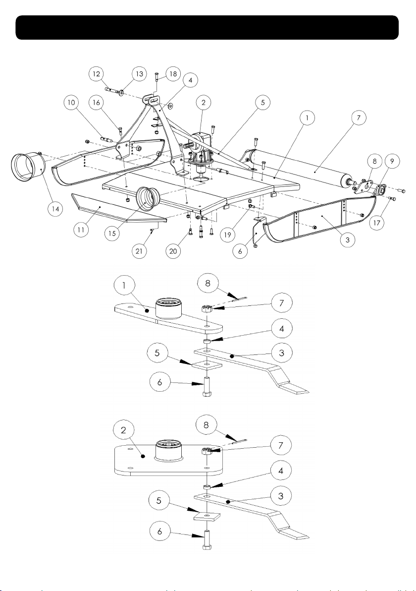
Spare Parts Diagram

ITEM NO PART NO DESCRIPTION QTY
1 641200 Main Chassis (Sabre 1200) 1
641500 Main Chassis (Sabre 1500) 1
2 01-004 Gearbox 1
3 1828.J3 Skid LH or RH (Sabre 1200) 2
1838.J3 Skid LH or RH (Sabre 1500) 2
4 681200 Headstock 1
5 691200 Rear Stay Sabre 1200 - (1 pair) 1 pair
691500 Rear Stay Sabre 1500 - (1 pair) 1 pair
B1230 Rear Stay Bolt, Nylock & Washer 2
6 691205 Grass Flow Vane (oponal) (Sabre 1200) 1
691505 Grass Flow Vane (oponal) (Sabre 1500) 1
7 981771 Rear Roller (Oponal) (Sabre 1200) 1
98771.01 Rear Roller (Oponal) (Sabre 1500) 1
8 988707 Rear Roller Bracket /Oponal (1 pair) 1
9 1199B Rear Roller Bearing only 2
1199A Bearing Housing 2
1199C Bearing Cover (obsolete) 2
10 5042 Lower Link Pin, Cat 1 2
11 147024 Front or Rear Guard 1200 (oponal) 1
147029 Front or Rear Guard 1500 (oponal) 1
12 5040 Top Link Pin, Cat 1 1
13 5040.01 Washers - Top Link Pin 2
14 21904.02 PTO Cone (For Clutch Opon) 1
15 21901 PTO Cone Std 1
FST PTO Cone Mounting Bolt M8 x 16 2
16 FST M16 x 40 Bolt, Nylock & Washers 2
17 FST M16 x 60 Bolt, Nylock & Washers 4
18 FST M16 x 50 Bolt, Nylock & Washers 3
19 FST M12 x 40 Bolt, Nylock & Washers 4
20 FST M16 x 50 Bolt, Nylock & Washers 4
21 Guard Mounng bolt/nut
ITEM NO PART NO DESCRIPTION QTY
1 1858 Blade Carrier, 2 Blade (Sabre 1200 & 1500) 1
2 1868 Blade Carrier, 4 Blade (Sabre 1200 & 1500) 1
3 1572 Flail Sabre 1200 (65 x 10 x 440) 2 or 4
1567 Flail Sabre 1500 (65 x 10 x 560) 2 or 4
4* 1778 Flail Bush 2 or 4
5 1849.J2 Retaining Plate 2 or 4
6* 188 Flail Bolt 2 or 4
7* 368 Castle Nut 2 or 4
8* 02-402 Split Pin 2 or 4
*188-P Flail Bolt Kit (2 of each items*)
FST
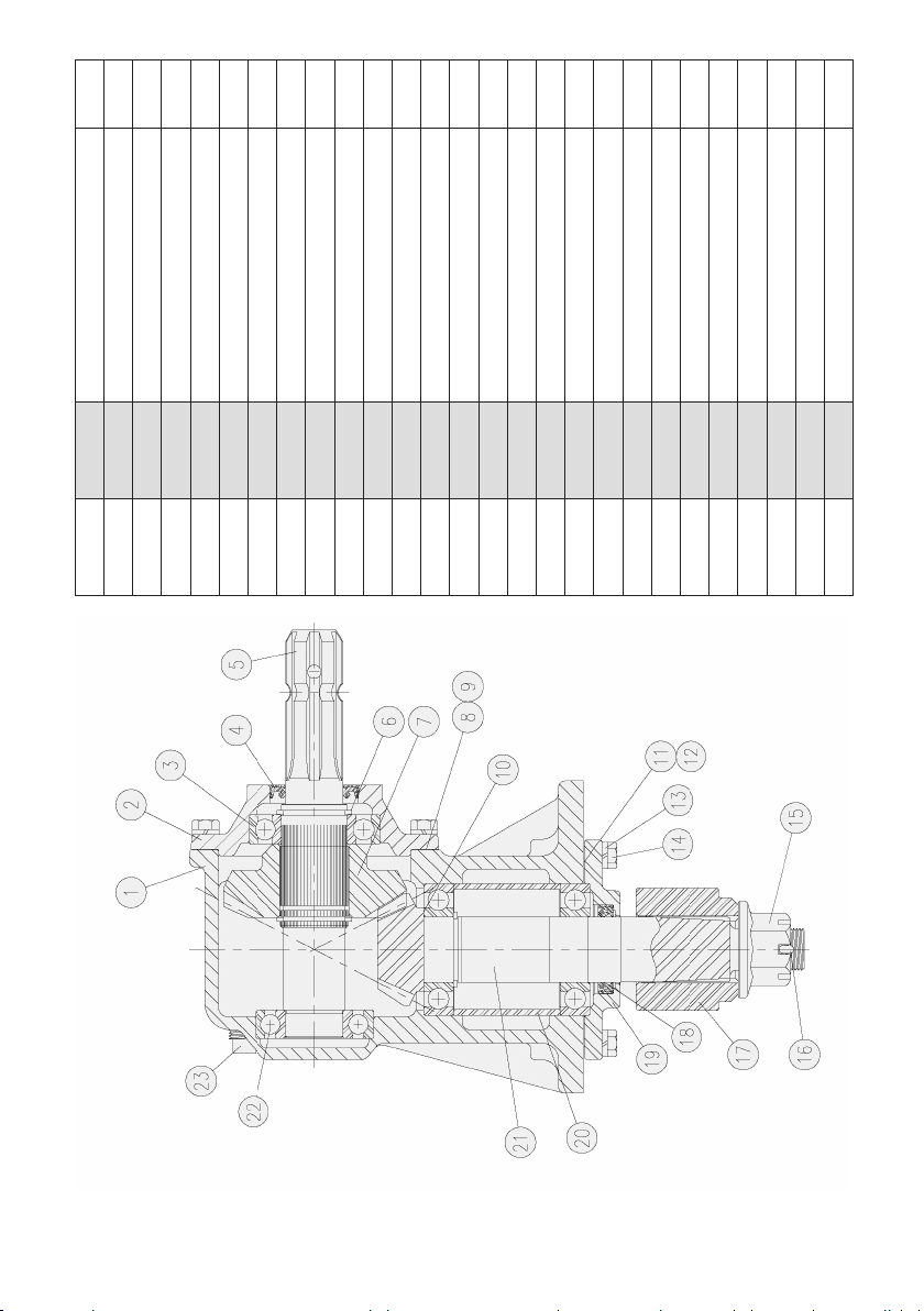
ITEM NO. PART NO. DESCRIPTION QTY.
1 18-010 Housing 1
2 20-007 Input Cap 1
34.03.101.03 Ball Bearing 208 3
45.02.106.06 Input Seal 1
5 02-034 Input Shaft 1
6 21-012 Retaining Ring 3
7 03-003 29 Tooth Input Gear 1
8 08-004A Input Gasket (0.30) VAR
9 08-004B Input Gasket (0.13) VAR
10 17-004 Steel Shim (0.20) 1
11 08-005A Output Gasket (0.30) VAR
12 08-005B Output Gasket (0.13) VAR
13 07-001 FST 10
14 06-008 3/8” - 16 X 1” Cap Screen 10
15 11-008 1” - 14 Slotter Flange Hex Nut 1
16 12-003 Cotter Pin 1
17 15-001 Blade Hub 1
18 5.04.105.33 Output Seal 1
19 20-003 Output Cap 1
20 10-002 Output Bearing Spacer 1
21 03-004 15 Tooth Output Sft & Pinion 1
22 4.03.104.02 Ball Bearing 207 1
23 09-002 1/2” Oil Fill Plug 1
24 09-005 1/8” Level Plug 1
N/L A4061007 Sabre 1200 Driveshaf
N/L A4086007 Sabre 1500 Driveshaft

This manual suits for next models
1
Table of contents
Other Fieldmaster Lawn Mower manuals


