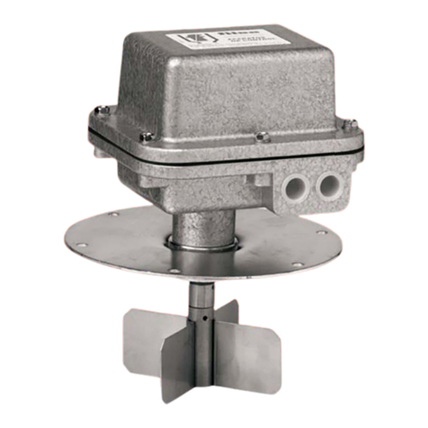
Filsa F9 User manual

Rotary blade level indicator for solids
F9
Operating Instructions
Talleres Filsa, S.A.U. www.filsa.es• • • • •E-08100 Mollet del Vallès (Barcelona) Tel. +34 93 570 46 01 Fax +34 93 570 24 71 [email protected] 01
06/14 MI-F9-EN-01© by FILSA
Page
Index
Safety instructions . . . . . . . . . . . . . . . . . . . . . . . . . . . . . . . . . . . . . . . . . . . . . . . . . . . . . . . . . . . . . . . . . . . . . . . . . . . . . . . . . . . 02
Operating instructions
1. Specification . . . . . . . . . . . . . . . . . . . . . . . . . . . . . . . . . . . . . . . . . . . . . . . . . . . . . . . . . . . . . . . . . . . . . . . . . . . . . . . . . . . . . . . 03
1.1 Intended use
1.2 Function
1.3 Technical data
1.4 Materials
1.5 Dimensions
2. Installation . . . . . . . . . . . . . . . . . . . . . . . . . . . . . . . . . . . . . . . . . . . . . . . . . . . . . . . . . . . . . . . . . . . . . . . . . . . . . . . . . . . . . . . . . 05
2.1 Preparing for use
2.2 Mechanical connection
2.3 Electrical connection . . . . . . . . . . . . . . . . . . . . . . . . . . . . . . . . . . . . . . . . . . . . . . . . . . . . . . . . . . . . . . . . . . . . . . . . . . . . . 06
3. Use . . . . . . . . . . . . . . . . . . . . . . . . . . . . . . . . . . . . . . . . . . . . . . . . . . . . . . . . . . . . . . . . . . . . . . . . . . . . . . . . . . . . . . . . . . . . . . . 06
3.1 Commissioning
3.2 Normal operation
3.3 Inexpert handling
4. Maintenance, servicing and spare parts . . . . . . . . . . . . . . . . . . . . . . . . . . . . . . . . . . . . . . . . . . . . . . . . . . . . . . . . . . . . . . . . 06
4.1 Maintenance
4.2 Servicing
4.3 Spare parts
5. Storage . . . . . . . . . . . . . . . . . . . . . . . . . . . . . . . . . . . . . . . . . . . . . . . . . . . . . . . . . . . . . . . . . . . . . . . . . . . . . . . . . . . . . . . . . . . . 06
6. Disposal . . . . . . . . . . . . . . . . . . . . . . . . . . . . . . . . . . . . . . . . . . . . . . . . . . . . . . . . . . . . . . . . . . . . . . . . . . . . . . . . . . . . . . . . . . 06

Read these Safety instructions before using the device for the first time and follow the Operating instructions.
Safety instructions
1. The installation, initial operation and maintenance should only be carried out by a qualified expert with electrical know-how.
2. Comply with the local and statutory rules and/or the VDE0100.
3. Before electrical connection, check the specifications on the data plate and the technical data of this manual.
4. A fuse must be connected in series to the supply voltage, according to the Standard and Normative documents.
5. Protect the signal contacts of the limit switch against voltage peaks when inductive or capacitive loads are connected.
6. Do not remove the Plastic protection inside the housing. It is a protection used to protect the motor-gear from the cables.
7. The device may be put into operation only if the electrical connection is correct. To secure the type of protection, the sealing cap and the gasket
must be placed correctly and the screw nut of the cable gland has to be fixed and fastened to the cable entry.
8. The earth connection of the device has to be installed in such a way that mechanical damage will be excluded.
9. Protect the controller from vibration and shakes. The vibration can provoke premature damage to the controller and may become useless.
10. The blade must not be hit by the filling stream. To avoid this, deflect the filling stream or install a deflection screen or a protection roof. It is also
recommended to install a protection roof when the controllers are used as empty-indicator or medium-indicator in silos where vaults could be formed
or where high loads above it could exist.
11. Avoid the installation of standard devices in ambient with vapour or with several changes of temperature. There are specific models for these
applications with different sealings rings and bearings that can extend the lifetime of the device.
12. Ask for rotary levels with the special sealing ring made of Stainless Steel-PTFE-Viton in applicactions with aggressive products or with micronized
bulk solids.
13. The connections of the single components as like as blade, shaft, extension, anti-buckling protection, etc. are permissible only with the attached
pins.
14. Switch off the power supply, before disconnecting the device.
F9
02 Talleres Filsa, S.A.U. www.filsa.es• • • • •E-08100 Mollet del Vallès (Barcelona) Tel. +34 93 570 46 01 Fax +34 93 570 24 71 [email protected]
06/14 MI-F9-EN-02© by FILSA

06/14 MI-F9-EN-03© by FILSA
Operating instructions
1. Specification
1.1 Intended use
The rotary blade level indicator F9 observes the filling level as a
limit switch. It can be used as indicator for dusty and powdery,
granulated and grainy bulk goods and are appropriated due to the
range of models and blades to control the level of bulk solids like
dust, flour, grain, sand, plastic, etc.
1.2 Function
1.3 Technical data
Manufacturer Talleres Filsa, S.A.U.
Address Bernat Metge, 33
08100 Mollet del Vallès
(Barcelona)
Name Rotary blade indicator
Type F9-... ref: 91...
Measuring blade speed 1 or 5 rpm depending on the
model
Switching voltage Standard 230 V AC (50 ... 60 Hz)
(Under request 115 V AC, 48 V AC, 24 V AC, 24 V DC due to a
converter)
4 VA in AC; 4 W in DC
3 3
Density of the product 0.01 t/m ... 2 t/m
Maximum pressure -0.5 bar ... +1 bar
(Under request up to +5 bar with sealing ring of Stainless Steel-
PTFE-Viton)
Cable entry 2 of M20x1.5
Under request up to
with a bulk density between
3
0.01 to 2 t/m . Although the characteristics of the product, humidity,
conductivity, grain size, etc. change, any adjustment is needed
These devices are used to control the level in silos, containers,
bunkers and they can be installed horizontally or vertically. For
vertical mountings there are rope shafts up to 10 m could be made
depending on the product to control.
The rotating measuring blade, projecting into the silo or container,
is driven by a gearmotor. If the bulk material reaches the
measuring blade, the rotation will be hindered and it will be
stopped. The return torque turns the pivoted motor from its end
position and actuates the signal switch. A second switch turns off
the motor off.
If the filling level of the bulk material sinks, the blade becomes
freely again and a spring will turn the motor back into its original
end position. Thereby the motor will be turned on again and the
signal switch will be switched back.
Power consumption
Maximum voltage of contact 4 V DC ... 250 V AC
Capacitity of the contact 1 mA / 4 V DC ... 2 A / 250 V AC
(for resistive loads)
For inductive or capacitive loads reduce at 50%
Bulk goods temperature -20 °C ... +80 °C
( +150 ºC)
Ambient temperature -20 °C ... +70 °C
Switching function 1 NO + 1 NC
Type of protection IP66 according DIN EN60529
Weight 1.2 kg ... 5 kg depending on the
model
1.4 Materials
Housing Aluminium, RAL 7001 coated
Process connection G 1 " 1/4 of Aluminium or G 1 " S.S.
depending on the model
Flange connection Aluminium, Zincated Steel or S.S.
depending on the model
Measuring blade S.S. 1.4301, shaft 1.4305
(Under request special models of S.S. 1.4401, Plastic or Gummy)
Sealing ring NBR
(Under request Stainless Steel-PTFE-Viton)
Rope shaft Stainless Steel
Rod shaft Stainless Steel
Protection tube shaft Zincated Steel
(Under request Stainless Steel)
1.5 Dimensiones
Approximate measures are given in mm.
F9
Talleres Filsa, S.A.U. www.filsa.es• • • • •E-08100 Mollet del Vallès (Barcelona) Tel. +34 93 570 46 01 Fax +34 93 570 24 71 [email protected] 03
130
92x88
130 115
Ø 110
F9-D F9-DR
F9-001
130
92x88
170 140
Ø 110
F9-002
125 or 180
50
115
100
Ø 200
F9-125 or 180
125 or 180
Ø 200
50
180
F9-125 or 180 with
pendulum shaft (UF)
F9-003 F9-004
92x88
115
92x88
length under
request,
max. 1.000 mm
Ø 200
50
125 or 180
F9-125 or 180 UF with
pendulum shaft extension
F9-125 or 180 UFM
extension with protecting
tube
shaft
F9-005
115
92x88
Ø 200
125 or 180
50
length under
request,
max. 2.000 mm
F9-006
140
92x88

F9
04 Talleres Filsa, S.A.U. www.filsa.es• • • • •E-08100 Mollet del Vallès (Barcelona) Tel. +34 93 570 46 01 Fax +34 93 570 24 71 [email protected]
06/14 © by FILSA MI-F9-EN-04
standard 2.000 mm,
other lenght under request,
max 10.000 mm
50
Ø 200
125 or 180
Ø 110
standard 800 mm,
other lenght under request,
max. 2.000 mm
272
68
F9-69 F9-C: standard according drawing
F9-C 69: model with blade 69 and
flange A-25-110
F9-007 F9-008
25
Ø 69 Set screw M6
15
55
Ø 69
30 15
Set screw M6
150
150
Ø 18
AC-25-150
AC-50-150
F9-015
F9-016
170
Ø 50
25
Ø 50
25
50
Ø 180
Ø 200
Flange connection
Threaded flange in all models G 1 " 1/4 female.
“H” Flanges in Zincated Steel
“A” Flanges in Aluminium
“I” Flanges in Stainless Steel
H-25-200
H-50-200
F9-011
F9-012
Ø 8
2.5
2.5
Ø 50
25
Ø 50
50
25
Ø 50
Ø 69
7
25
Set screw M6
8
50
Ø 69
7
Set screw M6
8
25
Ø 90
Ø 110
Ø 9
A-25-110
I-50-110
A-50-110
I-25-110
F9-017
F9-018
F9-019
F9-020
Ø 50
2
2
92x88
115
115
92x88
Ø50
Ø 50
50
25
I-25-200
I-50-200
F9-013
F9-014
25
2
2
100
92x88
120 115
G 1 " S.S.
F9-M:
blade speed 5 rpm
F9-010
100
92x88
120 115
F9-P or :
blade speed
F9-PR
5 rpm
F9-009
G 1 " 1/4
Aluminium

05/14 MI-F9-EN-05© by FILSA
F9
Talleres Filsa, S.A.U. www.filsa.es• • • • •E-08100 Mollet del Vallès (Barcelona) Tel. +34 93 570 46 01 Fax +34 93 570 24 71 [email protected] 05
Measuring blades
130
130
200
200
68
60
60
10
50
125 or 180
60
220
30
60
30
30
30
2. Installation
2.1 Preparing for use
-
- Verify if you got all the parts, the controller, blade with pin and
shaft extension if it was requested.
Read the Safety instructions and the Operating instructions before
using the controller.
2.2 Mechanical connection
There are models that can be mounted horizontally or vertically into
the silo.
The standard form is mounting the device with a flange, drilling
holes on the silo to allow the mounting of the controller using
screws, rods, fasteners or nuts. If the flange was not requested, the
thread is 1 " 1/4 or 1 " male, depending on the model and can be
fixed using 1 or 2 nuts or introducing it into a threaded socket with a
maximum of 25 mm length. If it is larger, the bulk goods have the
possibility to deposit in the thread socket. This could provoke that
the device becomes useless.
After the mounting is done, the housing could be turned in order to
face the cable gland correctly.
F9-021
F9-022
F9-024
F9-025
F9-027
F9-028
Diagonal blade F9-DR
and models with shaft
Diagonal blade F9-D
Blade X
F9-125 or F9-180
F9-69 blade
Hinged blade
Y 30x200
Hinged blade
T 30x200
125 or 180
10
50
Blade T F9-125
or F9-180
F9-026
7070
60
100
100
30
F9-023
Diagonal blade F9-P
and F9-M
50 70

Protection roof
2.3 Electrical connection
Connection diagram AC
Connection diagram DC
Cable gland
Sensitivity adjustment
For a right adjustment of the sensitivity modify
the position of the spring arm using pinces or
a screwdriver carefully.
- Fasten the cable gland after making the electrical connection.
- Fix and fasten the screw nut of the cable gland to make sure of
the water-tightness.
The blade must not be hit by the filling stream. To avoid this,
deflect the filling stream or install a deflection screen or a
protection roof. It is also recommended to install a protection roof
when the controllers are used as empty-indicator or medium-
indicator in silos where vaults could be formed or where high loads
above it could exist.
3. Use
3.1 Commissioning
- Put the controller into operation only if the installation and the
electrical connection have been done correctly.
3.2 Normal operation
- Use the device in its intended application only.
- Comply with the specifications
- If the controller is damaged, disconnect it immediately.
- It is forbidden to make changes to the device. This violates the
Normative.
3.3 Inexpert handling
- Ignoring the Safety instructions and the Operating instructions.
- Not intended use.
- Making changes or handling the controller.
- Violation against applicable Law and Standards.
- Using of non original parts.
4. Maintenance, servicing and spare parts
4.1 Maintenance
- If used correctly, no specific maintenance is required.
4.2 Servicing
- Check and review the state of the housing, the blade, shaft
extension if it was required and the correct commutation of the
electrical contact, as well.
4.3 Spare parts
- Use only original parts.
- The spare parts of the controller can be consulted in the document
“R-F9-01”.
5. Storage
- Store the controller in a dry and dust-free environment.
- Dismount the shaft together with the blade. Ensure that the shaft
of the level indicator with jib extension will not be buckled or
bended.
6. Disposal
-
- The controller can be recycled.
- The disposal applies to the valid environmental Guidelines
according to the location of the carrier and the local
manufacturing conditions.
on the data plate and the technical
data of this manual.
Switch off the power supply, before disconnecting the device.
F9
[
- Ground
1 - Supply voltage
2 - Supply voltage
4 - Normally closed
6 - Normally open
3 - Common
- Ground
1 - Positive: 24 V DC
2 - Negative: 0 V DC
4 - Normally closed
6 - Normally open
3 - Common
06 Talleres Filsa, S.A.U. www.filsa.es• • • • •E-08100 Mollet del Vallès (Barcelona) Tel. +34 93 570 46 01 Fax +34 93 570 24 71 [email protected]
05/14 © by FILSA MI-F9-EN-06
F9-029
F9-031
F9-030
[
220
160
1~
NL PE
11 2
346
1~
11 2
346
PE
AC
DC
250
V
2A
max.
AC-E
DF
6 4 3 1 1 2
50-
60Hz
4VA
Volt
220-240
110-120
48
24
L N
•
+
Protection roof
2.3 Electrical connection
Connection diagram AC
Connection diagram DC
Cable gland
Sensitivity adjustment
For a right adjustment of the sensitivity modify
the position of the spring arm using pinces or
a screwdriver carefully.
- Fasten the cable gland after making the electrical connection.
- Fix and fasten the screw nut of the cable gland to make sure of
the water-tightness.
The blade must not be hit by the filling stream. To avoid this,
deflect the filling stream or install a deflection screen or a
protection roof. It is also recommended to install a protection roof
when the controllers are used as empty-indicator or medium-
indicator in silos where vaults could be formed or where high loads
above it could exist.
Light:
spring.
Very light bulk goods. Low strain to the
Medium: Suitable for almost all bulk goods.
Medium strain to the spring.
Strong: For sticking bulk goods. Strong strain to
the spring.
F9-032
( )
( )
( )
FILSA constantly strives to improve its products and reserves the right to modify designs, materials and data without prior notice.
Keep this manual for further questions!
Table of contents
Other Filsa Touch Panel manuals
Popular Touch Panel manuals by other brands
Alula
Alula RE667W manual

Elo Touch Solutions
Elo Touch Solutions 17" X-Series user manual
Draper
Draper Smart Gym 503339 operating instructions

Crestron
Crestron QM-FTCC-TPS4 Operations & installation guide

AMX
AMX Modero Viewpoint MVP-5200i Operation/reference guide
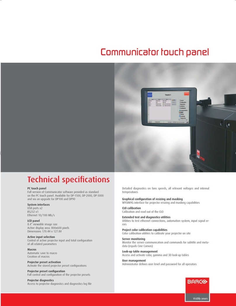
Barco
Barco Communicator Touch Panel specification

Belden
Belden thinklogical TPL-7 manual

Crestron
Crestron TPMC-3X Series Operation guide
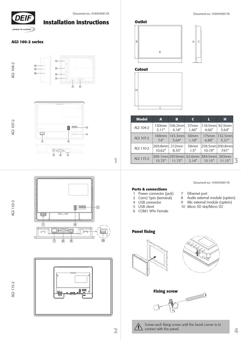
Deif
Deif AGI 100-2 Series installation instructions
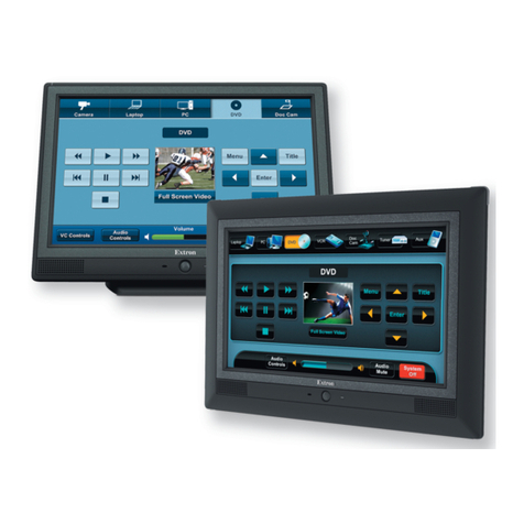
Extron electronics
Extron electronics TLP 1000MV user guide
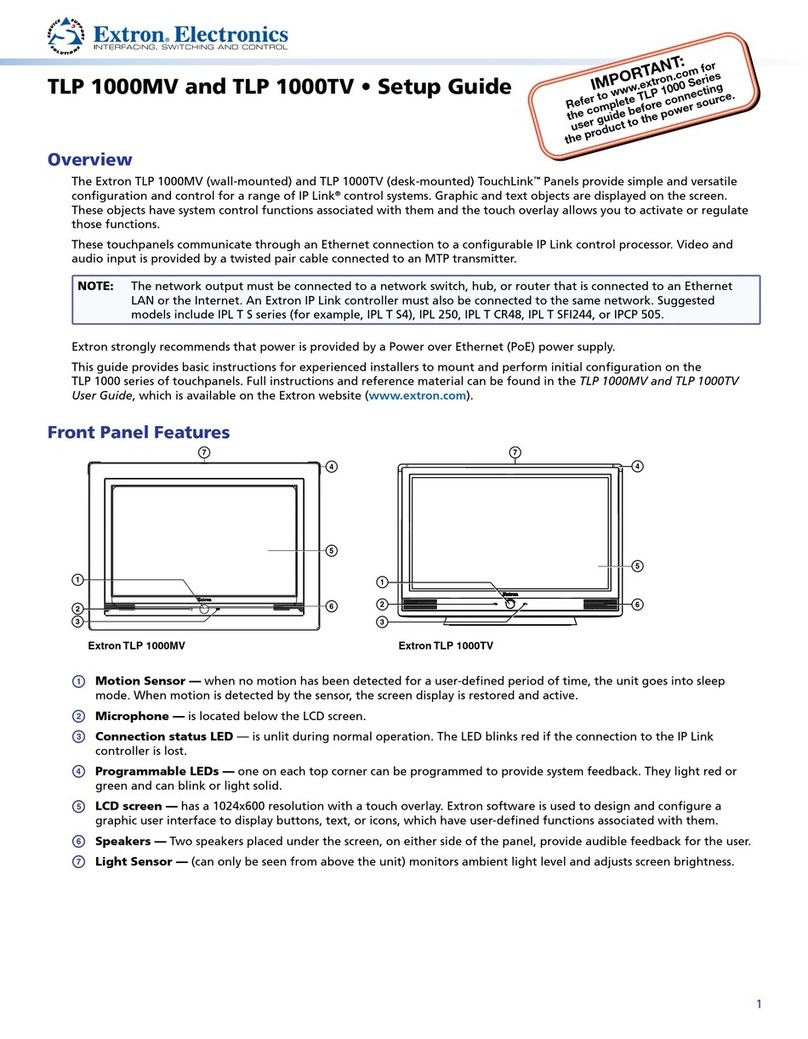
Extron electronics
Extron electronics TLP 1000MV Setup guide
Beijer Electronics
Beijer Electronics X2 control Hardware and installation manual
