Filser Electronic LX 500 8.0 User manual
LX500 Jan. 2002
Page 1
LX 500 8.0/6.0
GPS Navigation system
Jan. 2002
Filser Electronic G.m.b.H.
D-86875 Waal , Gewerbestrasse 2
Tel. 0049-8246-96990

LX500 Jan. 2002
Page 2
1 Contents
1 CONTENTS......................................................................................................................................................... 2
2 GENERAL........................................................................................................................................................... 3
2.1 TECHNICAL DATA .......................................................................................................................................... 3
2.2 KEYS AND KNOBS .......................................................................................................................................... 3
2.2.1 ON/OFF knob........................................................................................................................................ 4
2.2.2 Start key................................................................................................................................................. 4
2.2.3 Mode Selector (knob) ............................................................................................................................ 4
2.2.4 UP/Down Selector (knob) ..................................................................................................................... 4
2.2.5 ENTER key ............................................................................................................................................ 4
2.2.6 ESC key ................................................................................................................................................ 4
2.2.7 ZOOM (knob)....................................................................................................................................... 4
3 MODES OF OPERATION ................................................................................................................................ 5
3.1 SETUP .......................................................................................................................................................... 5
3.1.1 SETUP before passwod......................................................................................................................... 5
3.1.2 SETUP after password......................................................................................................................... 7
3.2 NAVIGATION USING LX 500 ........................................................................................................................ 12
3.2.1 GPS status display............................................................................................................................... 12
3.2.2 NEAR AIRPORT.................................................................................................................................. 13
3.2.3 APT airfields ....................................................................................................................................... 13
3.2.4 WPT Waypoints................................................................................................................................... 17
3.2.5 RTE (route).......................................................................................................................................... 19
3.2.6 Statistics .............................................................................................................................................. 20
3.3 FLYING USING LX 500................................................................................................................................. 22
3.3.1 Preparation on ground........................................................................................................................ 22
3.3.2 .................................................................................................................................................................... 22
4 COMMUNICATION LX 500-PC AND OTHER DEVICES ........................................................................ 23
4.1 COMMUNICATION LX 500-PC ..................................................................................................................... 24
4.2 COMMUNICATION WITH LX 20 AND COLIBRI .............................................................................................. 24
5 INSTALLATION .............................................................................................................................................. 25
5.1 WIRING ........................................................................................................................................................ 26
5.2 TREE STRUCTURE DIAGRAM ........................................................................................................................ 27
6 PASSWORDS.................................................................................................................................................... 28
7 CHANGES......................................................................................................................................................... 28
8 BASIC NAVIGATION TERMS...................................................................................................................... 29
LX500 Jan. 2002
Page 3
2 General
LX 500 is a compact unit corresponding to the 80 mm airnorm, that means very simple to build in and to use the
unit.The high power microcontroller guaranties a very fast reaction on user commands and display changes. The
main features are:
• Jeppesen data base for airfields and airspace
• 600 waypoints
• 100 routes
• flight statistic
• near airport function
The actual manual describes all instruments having program versions 6.0 or 8.0, regardless if new or upgraded.
2.1 Technical data
• Power suplly 8-36 V DC
• Power consumption ca. 150 mA /12V
• 80 mm air norm
• length 200mm
• NMEA output
• 12 GPS receiver
• PC interface
• Weight apr. 600 gr
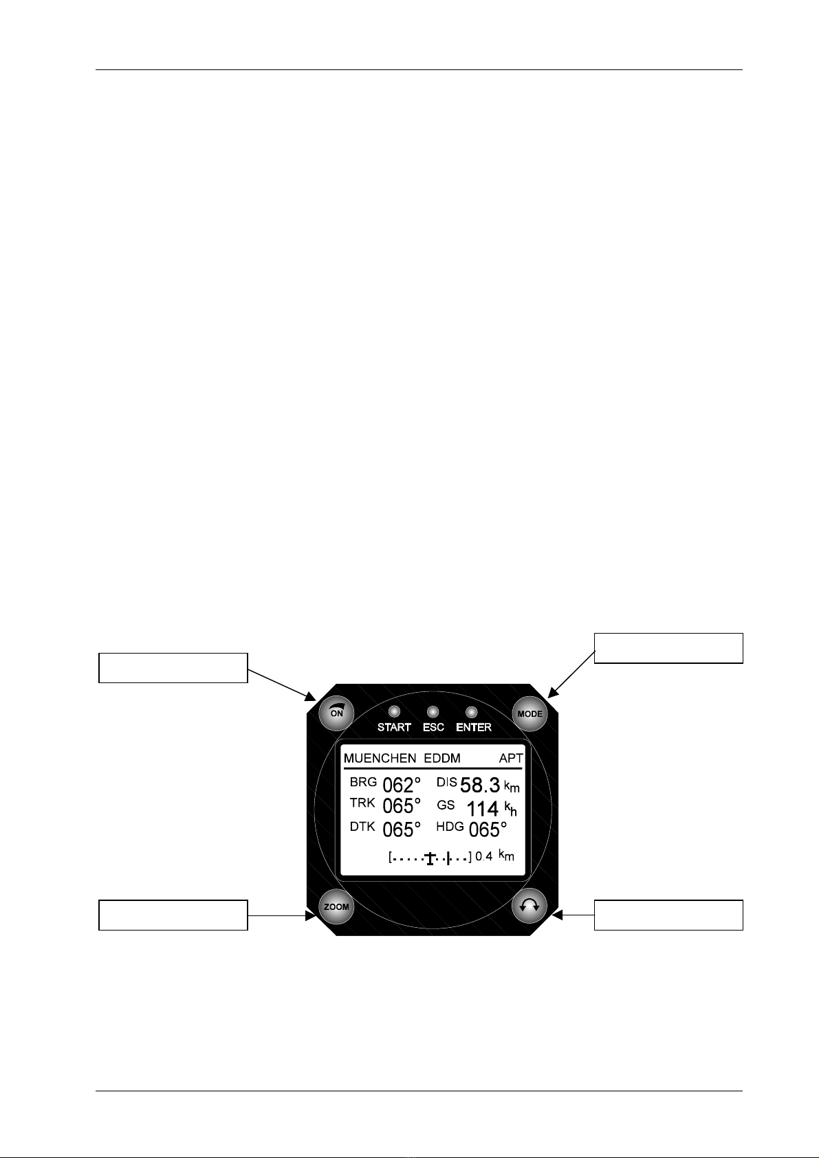
2.2 Keys and knobs
The unit controls consists of three knobs, three keys and ON/OFF knob
ON/OFF knob
Mode selector
Zoom Up/Down selector

LX500 Jan. 2002
Page 4
2.2.1 ON/OFF knob
After rotating to the right, the instrument will turn on and booting procedure will start. To switch the unit OFF
simple rotate the knob to the left again.
2.2.2 Start key
It is generally not an edit key, and therefore it is not used very often. It is mainly used to start the route or to over
jump one waypoint, which is not actual any more (flying RTE). Having done a mistake inputting data, you can use
start key to jump one position back.
2.2.3 Mode Selector (knob)
This is the key with the highest priority in the whole system. Its rotation will change mode of operation in any
way.
2.2.4 UP/Down Selector (knob)
The up/down selector is used to change pages in selected mode.
2.2.5 ENTER key
It is generally confirmation key; all edit functions of the LX 500 will start using it.
2.2.6 ESC key
During the flight the ESC key is not used very often, it is mainly used in edit procedures. The key has two main
functions:
• To jump one sub page higher, or to cancel any changes in edit procedure
• During edit procedures (when cursor is blinking) it is possible to confirm one row completely instead of
pressing ENTER more times.
2.2.7 ZOOM (knob)
The main task of the knob is to change zoom of the graphic screen. It is possible to use zoom knob to jump one
position back after a mistake has happened in edit mode (blinking cursor).
LX500 Jan. 2002
Page 5
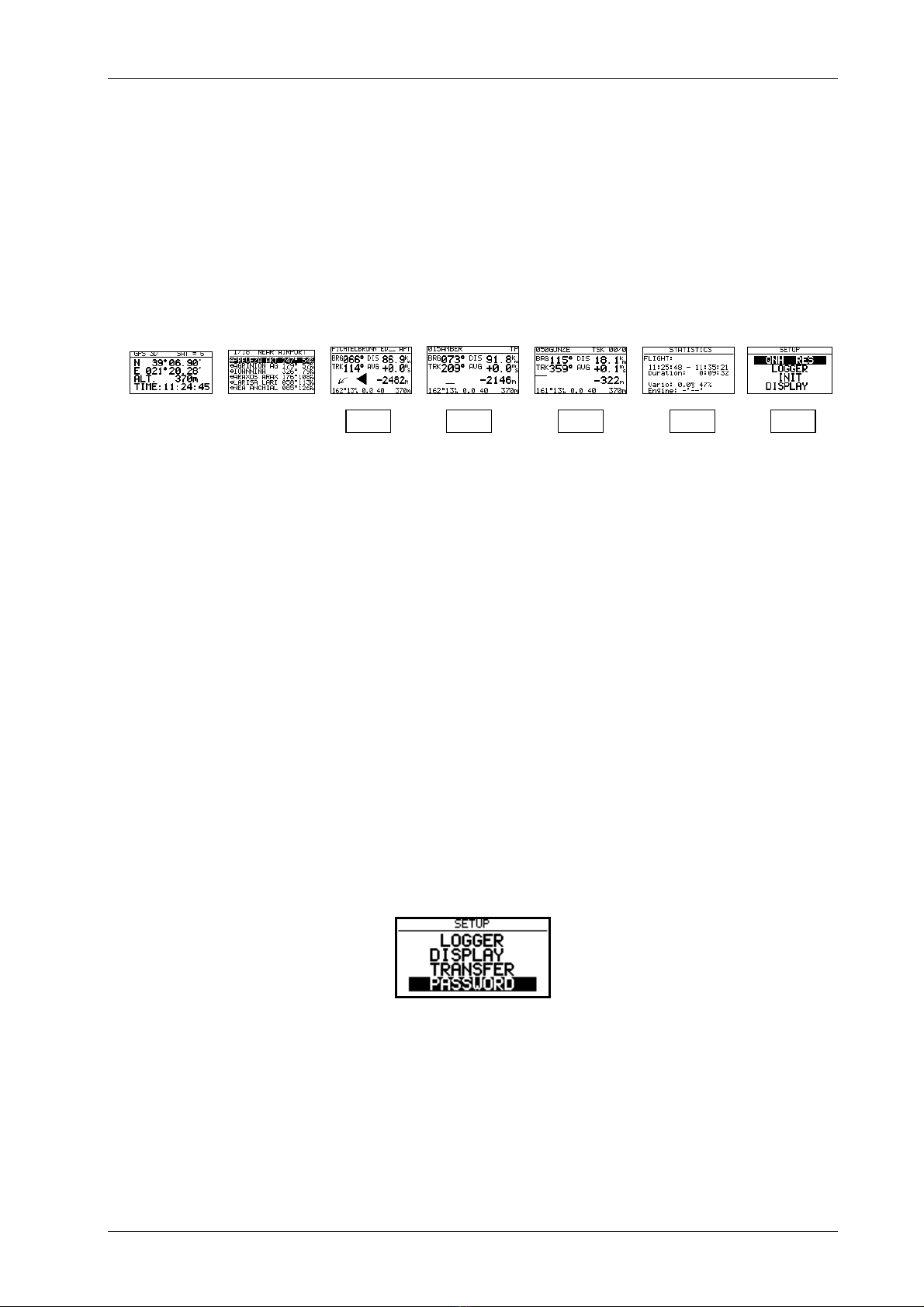
3 Modes of operation
The LX 500 works in 7 different modes of opereation. The mode selector rotating will select corresponding mode
directly. The diagram below shows the mode structure of LX 500.
⇐MODE⇒
GPS NEAR APT WPT RTE STATISTIK SETUP
⇓ ⇓ ⇓ ⇓ ⇓
⇓ ⇓ ⇓ ⇓ ⇓
The navigation modes (APT, WPT,RTE) have sub pages and they are available rotating up/down selector. See
appendix to find the complete three structure diagram of LX 500.
GPS GPS status, no edit
NEAR Near APT,VOR,NDB and conditionaly WPT
APT Navigation to an airport
WPT Navigation to the waypoint
RTE Navigation in RTE
STAT Flight statistics and logbook on the ground
Before using the instrument, plase set all necessary parameters of the instrument. To set your personal settings use
SETUP mode. Setup is organized in two levels, setup before password and setup after password.
3.1 SETUP
3.1.1 SETUP before passwod
All settings of that page can be changed every time and by anybody. To select corresponding item rotate up/down
selector.
LX500 Jan. 2002
Page 6
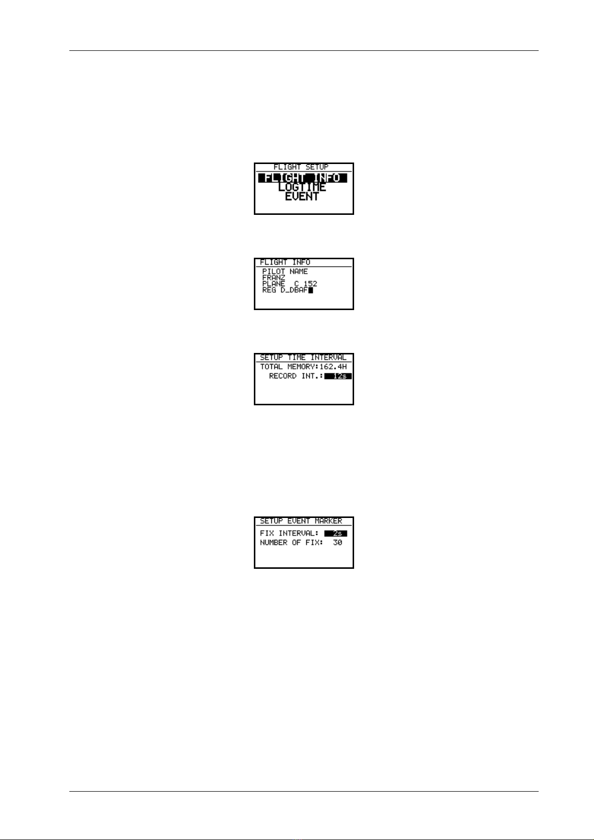
3.1.1.1 LOGGER
The logger data is stored in form of well known IGC format, that means for the flight analyses it is possible to use
all PC programs accepting IGC files( Lxe, SeeYou, Strepla, Opti …). After enter on LOGGER the input of pilot
name and airplane data is possible.
Record interval will define time intervals of position storing. Shorter intervals will reduce capacity of the memory.
Total memory indicator shows the capacity of the memory, this number will not go down after some flights will be
done. The number shows the pilot how many hours could he fly not to lossse some flights.The total memory
capacity depends on HW configuration of the instrument.
To arrange some adtional logger records use EVENT function. After activation some additioanl logger records will
follow under conditions set above. 30 additionl fixes will be recorded in two second intervals. To activate the
EVENT press START and ESC at the same time. A special message EVENT MARKED will appear after
activaction.
LX500 Jan. 2002
Page 7
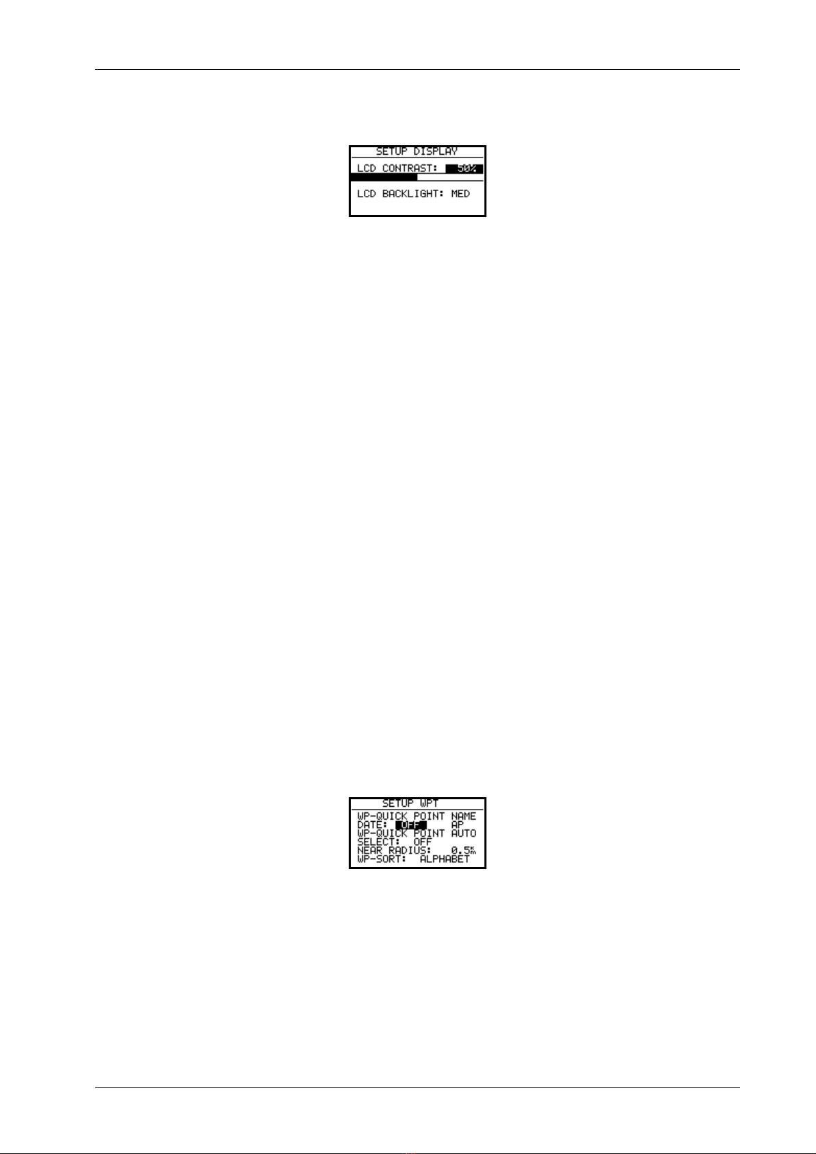
3.1.1.2 DISPLAY
LCD contrast setting will adapt the viwing angle, to read the display optimal. The dispay is of extended temperature
range additionaly internal temerature compensated. Using the instrument under extreme temperatures use contrast to
adapt contrast manualy.
3.1.1.3 TRANSFER
To exchange data LX 500 – PC use TRANSFER item. To start data transfer press enter. About details see further
paragraphs.
3.1.1.4 PASSWORD
After the input of 96990 the second part of setup will be available.
3.1.2 SETUP after password
Further 9 settings are allowed after input of the password. During the flight the password is inactive, that mans
selecting and cofirming PASSWORD with enter will open the menu.
3.1.2.1 MAGNETIC variation
Some types of GPS receivers built into LX 500 don’t deliver mg. variation. If the pilot wants to use mg. directions
the input of local deviation is mandatory.
3.1.2.2 WPT (Waypoints)
All settings referring to waypoints should be done using this menu.
WP-QUICK POINT NAME
It is possible to reproduce waypoints by storing of present. To determine the name of stored waypoint, two
possibilities are offered:
• DATE OFF will store present position like AP: XX: XX ( xx .xx is time)
• DATE ON will store present position like date and time for instance 24011230 for 24 January,12:30
LX500 Jan. 2002
Page 8
WP-QUICK POINT – AUTO
Stored waypoint can be selected automaticaly after generated or it can be selected later like all other waypoints.
NEAR RADIUS
This seting has nothing together with setings in OBS.ZONE. It defines near sector arround the waypoint. Flying
simple task (see paragrah flying LX 500).
WP-SORT
The waypoints can be sorted under alphabet or under distance respectivly. If distance sorting is taken, the nearest
waypoint will be offerd after selection procedure is started.
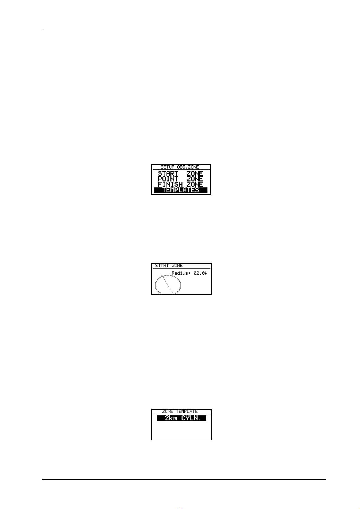
3.1.2.3 OBS.ZONE (oservation zones)
START ZONE
The pilot is able to defiene near radius of the start waypoint. After being inside START YONE the Route will start
and the next waypoint will be selected automatically.
POINT ZONE
The same like previous.
FINISH ZONE
Near area of the last waypoint of the route
TEMPLATES
Will refresh default setting 2 km.
LX500 Jan. 2002
Page 9
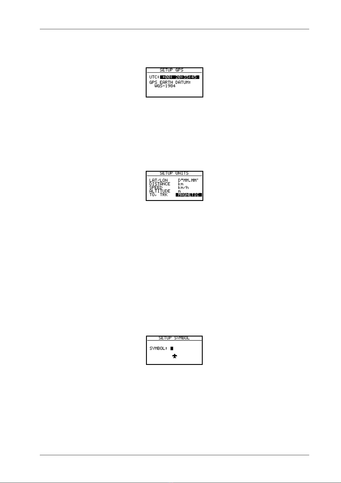
3.1.2.4 GPS
UTC offset to get local time indication can be arranged.
The GPS Earth Datum is set to WGS – 1984 and changes are not possible.
3.1.2.5 UNITS
Practically all known units and their combinations can be used.
• LAT, LON: decimal minutes or seconds
• DIST: km, nm, ml,
• SP (speed) : km/h, kts, mph,
• ALTITUDE: m, ft,
• BRG, TRK mag. (magnetic) or true (using mag. take care on variation)
3.1.2.6 GRAPHICS
SYMBOL
Two sizes of airplane symbol can be selected.

LX500 Jan. 2002
Page 10
AIRSPACE
The display of airspace is a very important feature of the instrument. To see the airspace it is oblligatory to set
AIRSPACE ENABLE. Not to overload the display with to much information it is very important to provide some
selection and to define under what conditions individual airspace will appear on the display. For each airspace there
are settings from OFF till ON. ON means that the airspace is always present on the display and OFF will remove the
airspace from the display. Settings from 5 up 100 km defines maximal zoom (selected by zoom knob) where the
airspace will be present. Using that methode the pilot is able to avoid owerloading of the display with graphic.
Exsample
50 km will show individual airspace only having zoom 50 km or lover. The producer offers following
configuration.
• CTR. control zone
• R.P,D restricted, prohibited, dangerous
• TRA training zone
• TIZ traffic information zones
• TMA terminal zone
APT
Airfiels with their symbols are present on the display too. The pilot is able to define zoom where the airfields will
appear on the display, the logic is identically like by airspace. The airports can be additionaly marked with ICAO or
first letters of the name.
Airspace type Visible by zoom 50km or lower
LX500 Jan. 2002
Page 11
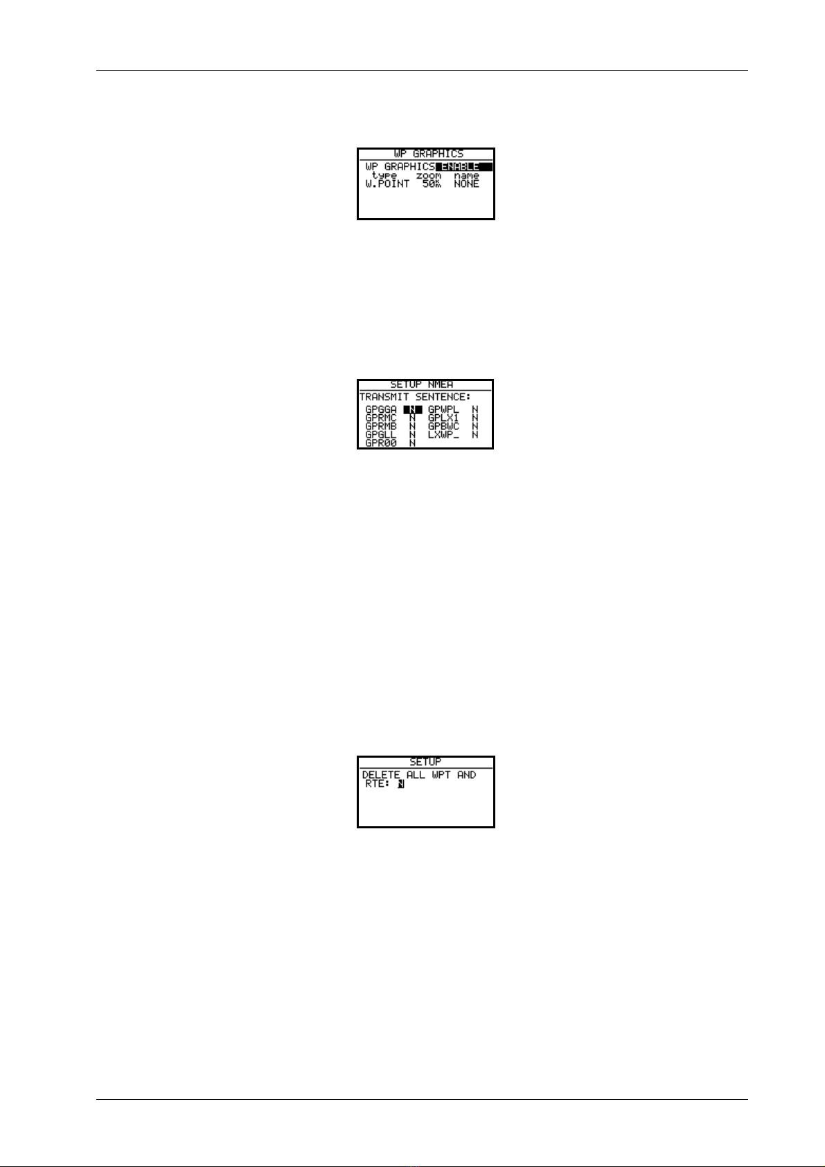
WPT
The same holds true for waypoints.
3.1.2.7 NMEA
The LX 500 is able to drive other navigation systems sending NMEA data sentences.
Factoty setting is N for all of them. Usualy used are GGA, RMC and RMB.
3.1.2.8 PC
Data transfer from LX 500 to PC and opposite will work only, if both of them use the same baud rate. The baud rate
can be adapted using this paragraph. Normal baud rate is 19200. The modern Windows programs (Lxe) are able to
adapt itself to the LX 500’s baud rate.
3.1.2.9 DEL WP/RTE
Using this command will delete all waypoints and routes definitively.

LX500 Jan. 2002
Page 12
3.2 Navigation using LX 500
Following navigation aids are offered:
• GPS status and coordinates
• Near airport
• APT, airport
• WPT, waypoints
• RTE, route
• STATISTICS inflight and logbook on ground
All mentioned modes are available using mode selector
3.2.1 GPS status display
Rotating up/down selector to the right will extend altiude indication with feet reading also.
The stop watch is working under following propositions.
• START result STOP: 0: 00
• START result RUN: 0:12
• START result STOP: 0:50
• START result STOP: 0:00 zero seting
• ENTER result TIME: 11:56:32 local time again
GPS Status and coordinates
Altitude in m and feet
Local time

LX500 Jan. 2002
Page 13
3.2.2 NEAR AIRPORT
Nearest airports, VORs, NDBs and waypoints (conditionally) will be shown in that page.
Important!
The waypoints with extension INCL.EMR will be displayed on the near airport page too. The waypoints have
different symbols to separate visualy airports from waypoints.
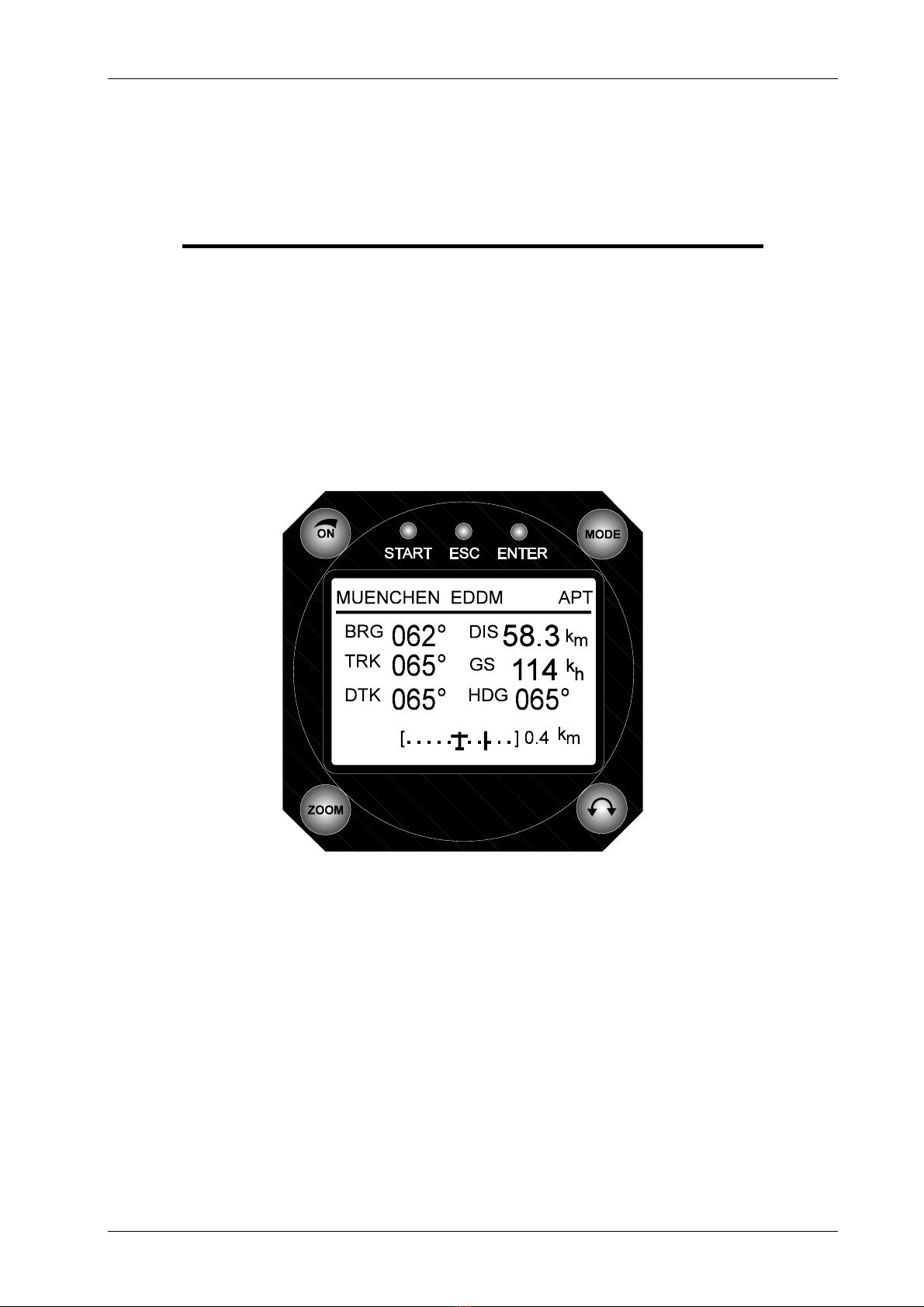
3.2.3 APT airfields
It is one of the three main navigation modes. The first page shows the elementary navigation data like bearing,
distance, ground track and ground speed. The CDI indicator is similar to that one used by VOR , but not
completely (see following paragraphs). Additionally information is brought to the next four pages, available after
rotating of up/down selector.
The capacity of LX 500 memory is more than 5000 airfields. It is not possible to edit the airfield data by the
instrument. The LX 500 is using Jeppesen database, and that database is not free. To update the database it is
possible exclusively using your PC. The data transfer will be successful having a code based on serial number and
data base version. The codes are available exclusively by Filser Electronic. The actual database can be
downloaded any time from www.filser.de or www.lxnavigation.si.
Waypoint
Airfield
Bearing and distance

LX500 Jan. 2002
Page 14
3.2.3.1 Navigate to APT
Five navigation pages can be used.
1. Navigation page
BRG bearing
DIS distance
TRK track
GS ground speed
DTK desired track (use zoom to select)
CDI indicator
The header is showing first 8 characters of the name and ICAO code. To extend name ( up to 16 characters) press
START.
2. Navigation page (graphic)
The display is divided into two parts, the right part consists of navigation data like name, bearing, track, distance,
ground speed and zoom . The left part is graphic showing airspace, airfields and waypoints. The airplane symbol
is always in the midlle of the screen and the map is moving. A straigt line following DTK (desired track) is going
to the airfield symbol. Changing of DTK during the flight will rotate the line also and the same will happen after GO
DIRECT. The upper side of the display is always oriented to the north. The zoom knob defines the area shown on
the display.
CDI indicator
Off course distance
DTK line

LX500 Jan. 2002
Page 15
3. Navigation page
This page is very similar to the first navigation page, with CDI indicator pointed out. Additionaly FROM/TO
indicator and arrrows are present to show the pilot to turn left or right to intercept the desired track. The FROM/TO
indicator shows the pilot, if the airplane is aproaching to the airport (TO) and opposite (FROM). Having difference
between bearing and track more than 90°, it means when FROM is indicated the distance will increase. The
TO/FROM indication doesn′t correspond with that one used by VOR.
The DTK defines the direction to the airfield and the deviation from that line is shown on the CDI. After selection it
is always bearing eqal DTK. That means the navigation from present position to the airfiled is possible without
addtionaly setting of DTK. Rotating DTK (zoom) a new direction can be preset and the CDI will show the
deviation. To arrange direct fligt to the airport from belivable position use GO DIRECT function. Press ENTER and
following menu will open.
Simply confirm GO DIRECT with enter and bearing will be equal DTK immediatelly, the CDI will be indicated in
the middle
4. Navigation page
ACT T. local time
ETA estimate time of arriwal
ETE estimate time enroute
ELEVATION airfield elevation
HOLD PATERN
LX500 Jan. 2002
Page 16
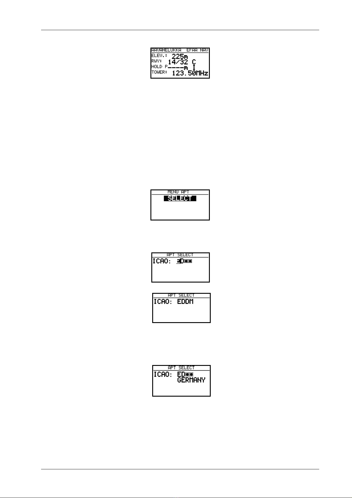
5. Navigation page
RWY runway direction and surface like concrete (C) or grass (G)
HOLD P. hold patern altitude and direction, I not defined
Imortant!
Those pages are practicaly the same by waypoints and RTE.
3.2.3.2 How to select an airport?
After pressing ENTER on select, the procedure will start.
There are two ways to select an airport, dierect way using ICAO code, and indirect using serching methode.
After input of EDDM Munich airport is selected directlly. By unknown ICAO confirm rest two stars with enter
(two times) or simply press ESC (once only).
Use up/down selector to to select counrty and confirm with enter.
LX500 Jan. 2002
Page 17
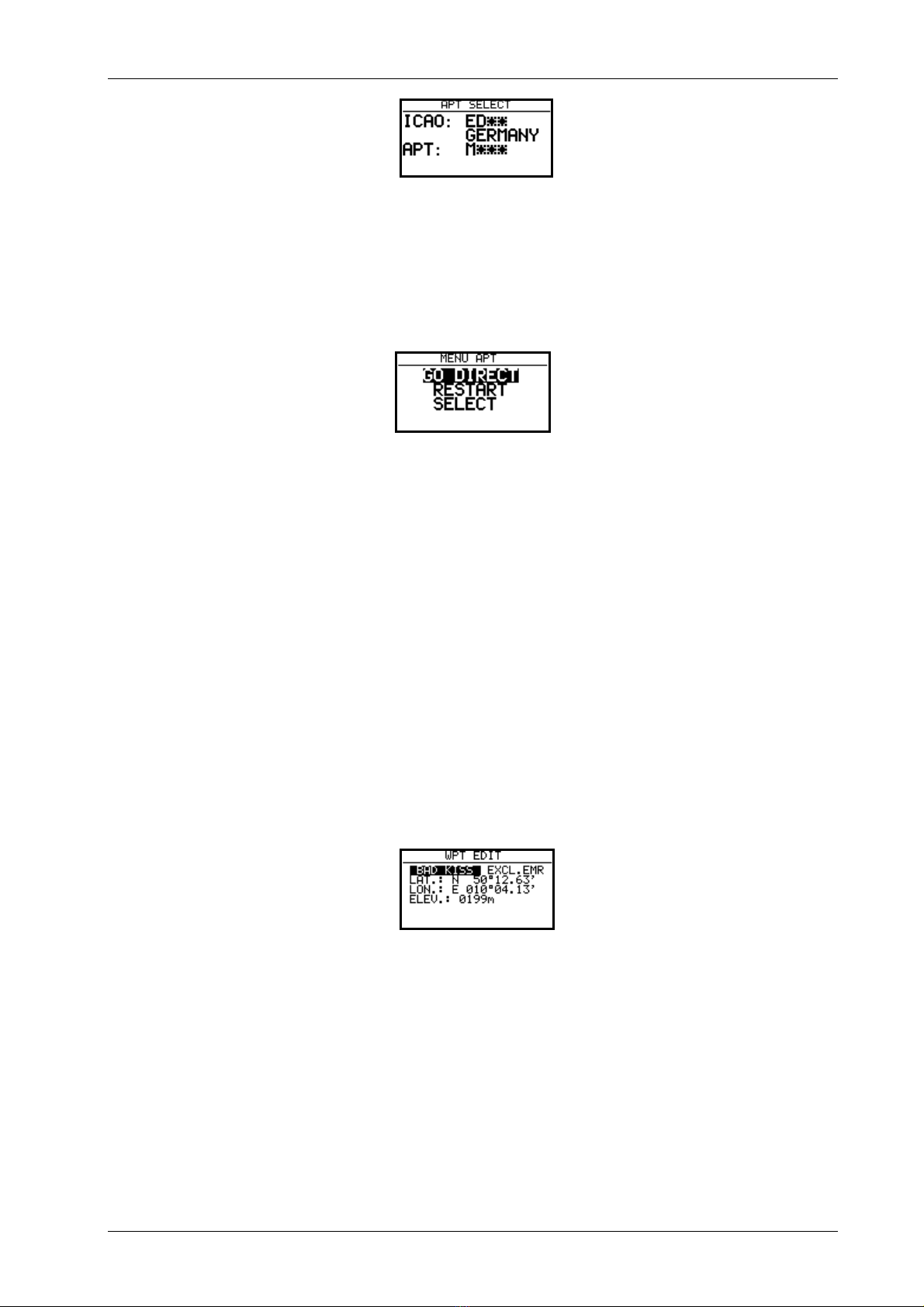
Define APT, VOR or NDB (up/down) and start with input of first letters of the airfield or nav. aid.
Input of lower amount of character (rest stars confirm with enter or escape) will offer more airports or nav. aids
having the same letters. To find the right one use UP/DOWN and enter.
During the flight two additional items will be added. GO DIRECT which was described just before. RESTART
will restart „simple task“. More about that see in the paragraph How to fly LX 500.
3.2.4 WPT Waypoints
The unit has capacity to store up to 600 waypoints, each name consist of maximum 8 characters. There are 4 ways to
get a new waypoint:
• Input of new waypoint manually
• Copy it from APT
• Data transfer from PC, Colibri or LX 20
• Storing of present positions
3.2.4.1 How to select a waypoint
The procedure is very similar to that used by airports. After ENTER on SELECT, EDIT and NEW menu will open.
It is to replace stars with the first letters of the name. Having selected sorting by distance the nearest waypoint will
appear on the top.
3.2.4.2 Edit Waypoint
Following data can be edited after the procedure started.
• name
• coordinates
• elevation
Waypoints can be included in the NEAR AIRPORT function. To use that feature input INCL.EMR.

LX500 Jan. 2002
Page 18
3.2.4.3 Input of a new waypoint
There are more ways to get a new waypoint into LX 500 database. After enter on NEW the procedure will start.
The copy procedure will copy one airport (or nav. aid) into waypoint database. After N a manual input of name,
coordinates and elevation will follow.
3.2.4.4 WPT delete
By using this function the waypoint will be removed from the database definitively.
3.2.4.5 WP QUICK (storing of present position)
After pressing START key the actual position will be stored like AP: (time), or date (see SETUP). Storing of
present position is possible only in waypoint mode.
Stored under time Stored like date and time
The nane and other data can be edited any time.
LX500 Jan. 2002
Page 19
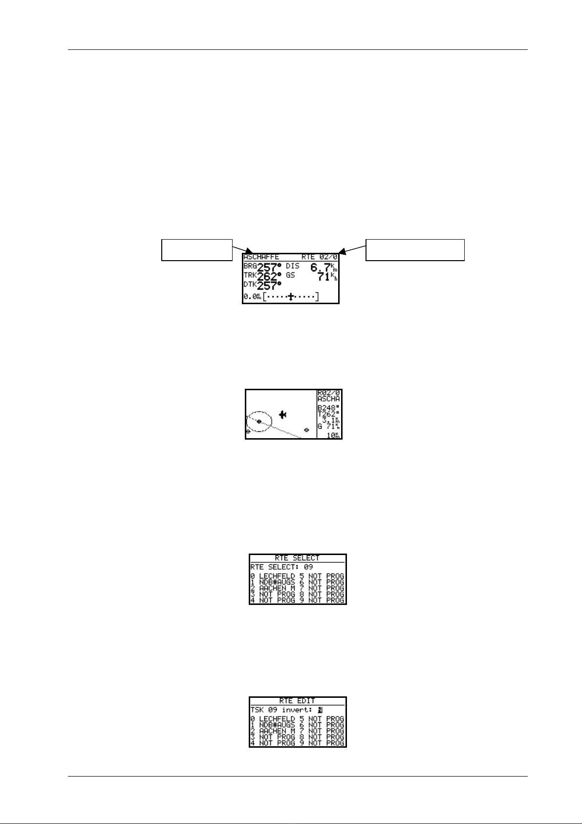
3.2.5 RTE (route)
LX 500 route consists of maximal 10 waypoints. The memory capacity is 100 routes. Using of route will bring
following advantages:
• Useable statistic during the flight
• Safe navigation from waypoint to waypoint (without selection)
• Simply to modify the route during the flight
• Automatic change over after reaching of waypoint
The menu structure is practically the same like by APT and WPT.
The only differency is the header where you can find name of the actual waypoint and its position in the route.
DTK is always set equal to BRG after selection. DTK can be changed during the flight.The graphical screen can
make a good job for the pilot, aproaching to the waypoint
The waypoint marked 0 is always the initial point of the route.
3.2.5.1 RTE select
The selection is done rotating up/down selector, RTE number and used waypoints will be shown. A NOT PROG
message will inform you that the route has not been programmed.
3.2.5.2 RTE edit
To modify the route use EDIT function. INVERT Y simple changes the numerical order of the waypoints.
name RTE nr. 2 point 0

LX500 Jan. 2002
Page 20
To modify individual waypoints put the cursor on the selected waypoint and press enter.
SELECT will replace existing waypoint with a new one
INSERT will insert a new waypoint one position higher.
DELETE will delete the waypoint definitively.
The selection can be done from WPT database or from the NAV database (APT, VOR, NDB). Selecting from NAV
will generate additional waypoints.
3.2.5.3 RTE new
Creation of new RTE is possible only having selected a NOT PROG before. The copy allows to copy a similar RTE
and simply modifying it.
3.2.5.4 Delete
Delete actual RTE definitively.
3.2.6 Statistics
There are two levels of statistics, in flight and on ground in form of a logbook.
This manual suits for next models
1
Table of contents


