FilterSense DynaCHARGE PM 1 Series User manual

INSTALLATION & OPERATING MANUAL
Particulate Monitor
Model DynaCHARGE™ PM 1
T: (978) 927-4304 | 800 Cummings Center, 355W Beverly, MA 01915 USA | www.ltersense.com


PM 1 Installation and Operating Manual v1.2 3FilterSense © 2016
Table of Contents
1Notifications..................................................................................................................................4
1.1 Technical Support Contact......................................................................................................................................................4
1.2 Disclaimer......................................................................................................................................................................................5
1.3 Symbols and Conventions ......................................................................................................................................................5
1.4Safety...............................................................................................................................................................................................6
1.5 Associated Documentation....................................................................................................................................................7
2Introduction..................................................................................................................................8
2.1 PM 1 Overview.............................................................................................................................................................................8
2.2 Components.................................................................................................................................................................................9
2.3 Technical Data............................................................................................................................................................................10
2.4 Model Configuration...............................................................................................................................................................12
3Installation ..................................................................................................................................13
3.1 Location........................................................................................................................................................................................13
3.2 Process Mounts..........................................................................................................................................................................15
3.3 Mounting.....................................................................................................................................................................................16
3.4 Test Port........................................................................................................................................................................................18
4Wiring ..........................................................................................................................................19
4.1 Terminal Connections.............................................................................................................................................................21
5Operation ....................................................................................................................................23
5.1 User Interface .............................................................................................................................................................................23
5.2 Settings.........................................................................................................................................................................................24
6Commissioning ...........................................................................................................................27
6.1 Signal Smoothing.....................................................................................................................................................................27
6.2 Alarms (PM 1-A).........................................................................................................................................................................28
6.3 Analog Output (PM 1-T).........................................................................................................................................................29
7AlarmSetpointGuidance...........................................................................................................30
8FunctionalVerification...............................................................................................................32
8.1 Power-Up Check........................................................................................................................................................................32
8.2 System-Zero Check..................................................................................................................................................................32
8.3 Response Testing......................................................................................................................................................................33
8.4 Factory Testing ..........................................................................................................................................................................33
9Troubleshooting.........................................................................................................................34
10 Maintenance................................................................................................................................35
11 Spare Parts ..................................................................................................................................36
11.1 Electronics Module Replacement.......................................................................................................................................36

PM 1 Installation and Operating Manual v1.2 4FilterSense © 2016
1 Notifications
1.1 Technical Support Contact
FilterSense provides industry leading Engineering and Technical Support for all product lines. The Technical
Support department is staffed with a team of engineering professionals. Areas of assistance provided by the
Technical Support department include:
Pre-Installation Site Analysis
Product Installation
General Operation
Application-Specific Review
Routine Calibration
EPA Compliance
Performance Upgrades and Add-On Features
To assure the best and most efficient technical support, please be prepared with the following information prior
to contacting FilterSense. If it is determined that the component must be returned for evaluation/repair, a
Return Material Authorization (RMA) number will be issued. You must include the RMA number on the packing
slip and mark the outside of the shipping container.
Company Name
Product Model Number
Product Serial Number
Date of Installation
Reason for Return
FilterSense Technical Support may be reached by:
Phone: (978) 927-4304
Fax: (978) 927-4329
E-Mail: [email protected]
Hours of Operation: 8:00AM 5:00PM U.S. Eastern Time
Any control unit or particulate sensor that was exposed to hazardous materials in a process must be
properly cleaned in accordance with OSHA standards and a Material Safety Data Sheet (MSDS) must be
completed before it is returned to the factory.
All shipments returned to the factory must be sent by prepaid transportation.
All shipments will be returned F.O.B. factory.
Returns will not be accepted without an RMA number.

PM 1 Installation and Operating Manual v1.2 5FilterSense © 2016
1.2 Disclaimer
This document contains important information necessary for proper operation of the product. It is
strongly urged that all users of the product read this manual in its entirety. All instructions should be
followed properly and any questions that arise should be discussed with FilterSense (A Division of Impolit
Environmental Control Corp.).
Any use or distribution of this document without the express consent of FilterSense is strictly prohibited.
Any reproduction is prohibitedwithout written permission.
In no event will FilterSense be liable for any mistake, including lost profits, lost savings, environmental
compliance costs, or other incidental or consequential damages or injury arising out of the use or
inability to use this manual, even if advised of the possibility of such damages, or any claim by any other
party. Terms and conditions supplied with each order contain additional liability limitations related to
this product.
1.3 Symbols and Conventions
Identifies information about practices or circumstances that can lead to personal injury
or death, property damage, or economic loss.
Warning statements help you to:
Identify a hazard
Avoid a hazard
Recognize the consequences
Identifies information that is critical for successful application and understanding of
the product.
Identifies information, sections or statements in this manual that apply to approved
hazardous area systems, regulations, or installation.

PM 1 Installation and Operating Manual v1.2 6FilterSense © 2016
1.4 Safety
AREA CLASSIFICATION
Before installing any device, confirm area classification requirements as specified on
the product label. Do not install any device that is not tagged as suitable for the
required area classification.
ENVIRONMENT
Before installing any device, confirm ambient temperature, process temperature, and
process pressure requirements. Do not install any device that is not tagged as suitable
for the required temperatures and pressures.
NOT A SAFETY RATED DEVICE
This model must not be used independently for safety or as a critical input signal to a
safety system. This model is designated for general process control, diagnostics, and
environmental monitoring. Safety must be addressed with the detailed engineering,
redundancy, and safety certified components where applicable. Consult factory for
critical safety applications.
GROUNDING
Before turning on the instrument, you must connect the protective earth terminal of
the instrument to a proper earth ground. Grounding to the neutral conductor of a
single-phase circuit is not sufficient protection.
INSTALLATION AND SERVICE PERSONNEL
Only appropriately licensed professionals should install this product. Always
disconnect power before servicing.
Personnel must be familiar with operational hazards, such as those caused by hot,
pressurized, or toxic gases, liquids, or particulates.
Service of individual electronics is limited to replacement of the electronics module. Do
not attempt to disassemble electronics. Any components that are not operating
properly should be returned to FilterSense for service.

PM 1 Installation and Operating Manual v1.2 7FilterSense © 2016
1.5 Associated Documentation
This manual is to be referenced in conjunction with the following FilterSense documentation:
Product Information
Publication Number
Title
228-1077
FilterSense Particulate Monitoring Application and Alarm Guide
EXXXX
Project Specific Drawings if Applicable

PM 1 Installation and Operating Manual v1.2 8FilterSense © 2016
2 Introduction
2.1 PM 1 Overview
a single-point/basic functionality particulate monitor employing charge induction
sensing for reliable continuous monitoring of particulate in stacks, ducts, and pipes. Applications include filter
leak detection, cyclone overflow, and powder flow/no flow. The PM 1 is available in two versions.
PM 1
PM 1-A
oBasic Particulate Monitor with Alarm
Relay Outputs
oIntegral Electronics Only
PM 1-T
oBasic Particulate 4-20mA Transmitter
oIntegral Electronics Only
The PM 1 is also available in a PRO version for demanding process control and EPA compliance applications.
Refer to separate manual for the PM 1 PRO.
PM 1 PRO
PM 1 PRO-A
oAdvanced, High-Performance Parti-
culate Monitor with Alarm Relay
Output
oIntegral or Remote Electronics
oGraphical Display/Keypad
PM 1 PRO-AT
oAdvanced, High-Performance Parti-
culate Monitor with Alarm Relay
Outputs and Analog Output
oIntegral or Remote Electronics
oGraphical Display/Keypad
PM 1 PRO-T
oAdvanced, High-Performance Parti-
culate 4-20mA Transmitter
oIntegral or Remote Electronics
oGraphical Display/Keypad

PM 1 Installation and Operating Manual v1.2 9FilterSense © 2016
Principle of Operation
As particles flow near or around the electrically
isolated sensing probe, minute charge is continuously
induced into the probe. The charge flows through a
measurement circuit to ground.
The induced charge signal is digitally analyzed and
processed to provide an output that is reasonably
linear to mass. The unit of measure is picoamperes
(pA). For highest accuracy and linearity to mass, refer
to model PM 100 PRO.
For best understanding of particulate levels, 4-20 mA
analog outputs should be converted to pA at remote
recording devices or remote displays.
2.2 Components
The PM 1 consists of the following main elements:
① Electronics Module
② Electronics Enclosure
③ Process Mount
④Sensing Probe

PM 1 Installation and Operating Manual v1.2 10 FilterSense © 2016
2.3 Technical Data
Electronics Module
Parameter
Model Code
Specifications
Notes
Measurement
Technology
Charge Induction
Measurement Units
Picoamperes (pA)
1 x 10-12 A
Input Voltage
-A-U
-A-D
-T
Universal 20-250 VAC/VDC, 47-63 Hz
18-60VDC
Fuse: 1.0A, Slo-
12-32 VDC Loop Power
Input Power
-A
3 Watts Max.
Electronic Resolution,
Range
-R1
-R2
-R9
0.5pA, Range 0 to 5,000pA
5.0pA, Range 0 to 5,000pA
10.0pA, Range 0 to 100,000pA
Powder Flow Only
Minimum Detection
Level
-R1
-R2
-R9
~1-5 mg/m3
~5-10 mg/m3
~10 mg/m3
Minimum Particle Size
0.3 Micron
Temperature Ambient
-13F to +160F (-25C to +71C)
-40F to +185F (-40C to +85C)
Operating
Storage
Relay Outputs
-A
Form A (SPST)
250 VAC / 5A (Resistive), 2A (Inductive)
30 VDC / 5A (Resistive), 2A (Inductive)
Type
Max Rating
4-20mA Output
-T
@ 24 VDC
Loop Power
Adjustable via Keypad
Rating
Span
Enclosure
-N4
NEMA 4/IP 66 Aluminum, Powder
Coated
Area Classification
-G
-H2
Ordinary/General Purpose Only, CE
Approved (CSA/UL Approval Pending)
Optional Hazardous Location, CSA
Approved, Class II, Division II, Groups E-
G, ATEX, IECEx (Approval Pending)

PM 1 Installation and Operating Manual v1.2 11 FilterSense © 2016
Sensor Probe
Parameter
Detail/Code
Specifications
Notes
Mounting
-N05
-B10
-Q15
NPT Male 0.5 in
BSPT Male 1.0 in
Quick Clamp, 1.5 in
Wetted Materials
-C
316L Stainless Steel
Optional Fully Insulated Probe (Teflon
Coating)
316L Stainless Steel, Teflon
Probe
Nipple/Mount
Process Temperature
Operating Range
-T12
-T14
-13F to +250F (-25C to +121C) Max.
-13F to +450F (-25C to +232C) Max.
Process Pressure
Operating Range
Full Vacuum to 10PSI (0.69 Bar) Max.

PM 1 Installation and Operating Manual v1.2 12 FilterSense © 2016
2.4 Model Configuration
DynaCHARGE™ PM 1 Particulate Monitor
Order
Code
Base Unit
Transmitter (4-20 mA), 2-Wire Loop Power
PM 1-T
Alarm (2 Relays)
PM 1-A
Power Supply (PM 1-A Only)
Universal AC/DC Power (20 to 250 VAC/VDC)
U
DC Power Only (18-60 VDC)
D
Resolution and Range
Resolution: 0.5 pA, Range: 0 to 5,000 pA
R1
Resolution: 5.0 pA, Range: 0 to 5,000 pA
R2
Resolution: 10.0 pA, Range: 0 to 100,000 pA
R9
Probe Length
Length - 1.5 in (3.8 cm)
L1.5
Length - 3.0 in (7.6 cm)
L3
Length - 6.0 in (15.2 cm)
L6
Length - 12 in (30.5 cm)
L12
Length - 18 in (45.7 cm)
L18
Length - 24 in (60.9 cm)
L24
Length - 30 in (76.2 cm)
L30
Length - 36 in (91.4 cm)
L36
Process Mount
NPT Male 0.5 in (1.3 cm) with Mounting Coupling
N05
Optional - Remove NPT Mounting Coupling
R
BSPT Male 1.0 in (2.5 cm) with Mounting Coupling
B10
Optional - Remove BSPT Mounting Coupling
R
Quick Clamp, 1.5 in (3.8 cm) with Mounting Kit (Z= Mount Extension Size in Inches)
Q15(Z)
Optional - Remove Quick Clamp Mount Kit
R
Process Temperature
-13 °F to 250 °F (-25 °C to 121 °C) Max.
T12
-13 °F to 450 °F (-25 °C to 232 °C) Max.
T14
Process Pressure
Full Vacuum to 10 PSI (0.69 Bar) Max.
P0
Additional
Fully Insulated Probe (Teflon Coating)
C
Enclosure
NEMA 4/IP 66 Aluminum, Powder Coated
N4
Area Classification
Ordinary/General Purpose Only, (Approval Pending), CE Mark
G
Hazardous Location, Class II, Division II, Groups E-G, CSA/FM, ATEX, IECEx (Approval
Pending)
H2

PM 1 Installation and Operating Manual v1.2 13 FilterSense © 2016
3 Installation
Only trained professionals should install/maintain this product.
Shutdown processes that include high temperatures, high pressures, toxic
gases, hazardous particulate, or explosion risks prior to installing or removing
equipment.
3.1 Location
Temperature, Pressure, and Area Classification
Do not install any device that is not tagged as
suitable for the required area classification.
Confirm compatibility of sensor ratings with
process and installation area.
Check label for the following:
oProcess temperature rating
oProcess pressure rating
oWetted materials
oEnclosure rating
oArea classification
Installation must be in grounded metal
duct/pipe. Consult factory for non-metallic
duct/pipe solutions.
Enclosure Label Example
Filter Outlet Locations
①Ensure good access.
②Avoid locating too close to stack exit.
③Straight runs and laminar flow best for
measurement.
④ Short straight runs are acceptable for basic
leak detection.
⑤Accessible negative pressure locations may be
preferred to prevent exposure to toxic gases
and particulate.
④
③
⑤
①
⑤
③
②
PM 1 Installation and Operating Manual v1.2 14 FilterSense © 2016
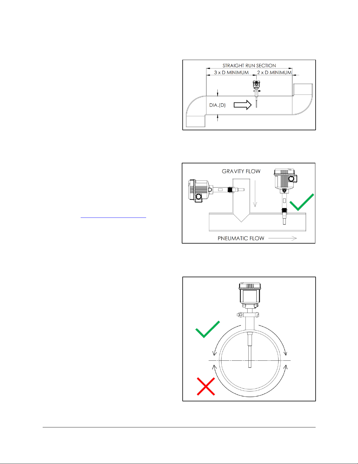
Straight Run Considerations
Install in straight run if possible (not required).
Three (3) duct diameters upstream.
Two (2) duct diameters downstream.
Straight run can be horizontal or vertical.
Powder Flow Locations
①Best installed in pneumatic section (positive
or negative pressure).
②For gravity feed, consult factory.
Grounded metal duct required.
oConsult factory for nonmetallic duct/
pipe solutions.
Follow straight run considerations.
Horizontal Pipes/Ducts
Side or top mount recommended.
Bottom mount notrecommended.
Proper mount and installation location will
prevent buildup.
①
②

PM 1 Installation and Operating Manual v1.2 15 FilterSense © 2016
3.2 Process Mounts
The following types of process mounts are available:
Threaded
NPT Standard
G/BSPT Optional
① Threaded Nipple
② Threaded Half-Coupling Process Mount
Quick-Clamp
-Clamp
Allows quick and easy removal from process
Allows rotation to easily align
① Quick-Clamp Nipple
② Quick-Clamp Process Mount
①
②
①
②

PM 1 Installation and Operating Manual v1.2 16 FilterSense © 2016
3.3 Mounting
Mounting Considerations
①Process mount should protrude into process
0.125 in (3.175 mm) to 0.5 in (12.7 mm).
②Sensor probe should extend approximately
1/2 of the duct diameter for filter outlet
applications and 1/4 to 1/2 of the pipe
diameter for powder flow applications.
In smaller pipes, the probe should be 1 in
(25.4 mm) minimum from the opposing side.
Welding and Clearance
①-clamp
mount to ensure proper clearance and to
prevent particulate buildup in mount. Process
mount should protrude into process 0.125 in
(3.175 mm) to 0.5 in (12.7 mm).
②Do not face weld.
Weld in center of the duct/pipe,
perpendicular to the flow.
Air and water tight seal.
Quick-Clamp
Threaded
①
①
②
②
②
②
①
①

PM 1 Installation and Operating Manual v1.2 17 FilterSense © 2016
Improper Extensions
①Do not use an extended or improper mount.
②Longer mounts can cause the nipple not to
protrude into the process.
③Extended mounts can cause particulate
buildup on the insulator and sensing probe.
Contact the factory for custom sensor nipple
extensions for proper installation in an
existing port.
Do not use non-stainless steel mounts that
may corrode and cause corrosive residue to
drip on the sensor.
①
②
③

PM 1 Installation and Operating Manual v1.2 18 FilterSense © 2016
3.4 Test Port
Installation of a sensor test port is for introducing particulate upstream of the sensor as a method for checking
the response to an increase in particulate. Some applications are required by EPA regulations to include a sensor
test port for Response Testing.
Location and Mounting
Non-hazardous areas only.
Negative pressure location.
Install at least 3 ft upstream of the particulate
sensor.
In line with sensor on the same side of the
duct.
If possible, locate the test port at ground level
and/or a location with easy access.
If the test port must be located at an
inaccessible location, a length of tubing can
be used to improve access.
Typical test port is a
with a cap or shutoff valve.

PM 1 Installation and Operating Manual v1.2 19 FilterSense © 2016
4 Wiring
Conduit Entries
One (1) and two (2) NPT entries
provided.
Conduit fittings should be tight.
Conduit should be routed downward to
prevent moisture from entering enclosure.
Recommended Service Loop
Flex conduit and ground cable should be
sufficient length to allow removal of the
sensor.
Recommended service loop is 1 to 2 times the
sensor probe length.
Service loop should extend downward to
prevent moisture from entering enclosure.
PM 1 Installation and Operating Manual v1.2 20 FilterSense © 2016
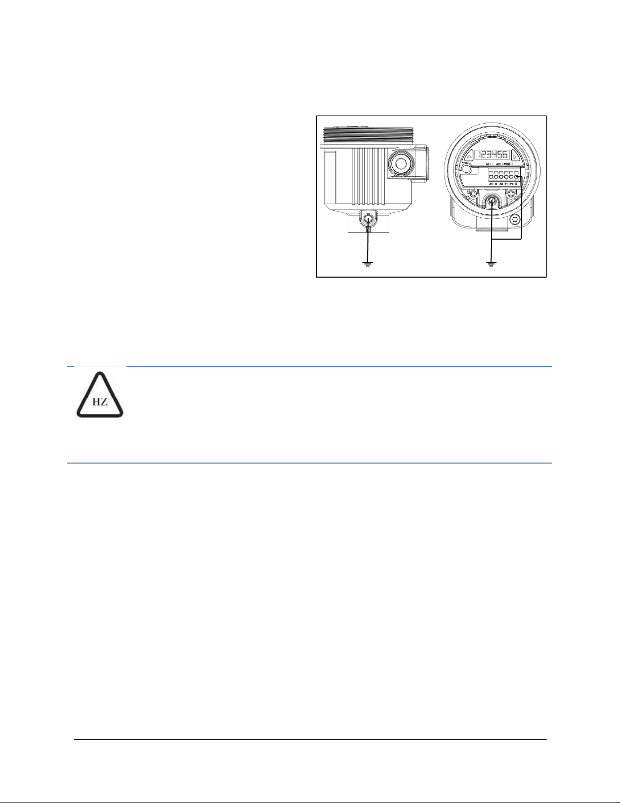
Grounding
Required for reliable operation and safety.
PM1-T: Earth ground connection is made
through the process mount. Grounding to the
enclosure ground studs is not required.
PM1-A: Earth ground connection should be
made to one of the three ground locations:
oExternal enclosure ground screw.
oInternal enclosure ground screw.
oElectronics module earth ground
terminal.
Analog wiring cable shield should be
terminated to earth ground in PLC/DCS
cabinet or at panel meter (terminate at one
end only).
Ground wire should not impede service loop.
GROUNDING IN HAZARDOUS AREAS
For hazardous area applications, an external sensor earth ground cable is
required to maintain sensor grounding during installation and maintenance.
The ground cable must remain attached when the sensor is temporarily
removed from the process. Do not disconnect the ground cable.
This manual suits for next models
5
Table of contents
Popular Accessories manuals by other brands

Aztech
Aztech KylaS WiFi Plug UK Easy start guide

Johnson Controls
Johnson Controls NS Series installation instructions

ALLDOCK
ALLDOCK To Go Assembly instructions

Milesight
Milesight VS121 user guide

DH Instruments
DH Instruments EXTERNAL RESERVOIR FOR PPCH instruction sheet

MKS
MKS HPS 903 Series Operation and maintenance manual


