manuals.online logo
Brands
  1. Home
  2. •
  3. Brands
  4. •
  5. Texecom
  6. •
  7. Accessories
  8. •
  9. Texecom PRESTIGE HD User manual

Texecom PRESTIGE HD User manual

8 ALTERING COVERAGE AT 2m
MOUNTING HEIGHT
6 ANGLING THE DETECTOR
4
3 STANDARDS & APPROVALS2 ENVIRONMENTAL1 PHYSICAL
8m
26
'
2
"
10m
32
'
9
"
15m
50
'
15m
50
'
2m
6'7"
2m
6'7"
2m
6'7"
2m
6'7"
-35°C (-31°F) to +60°C (+140°F)
150g (5oz) approx.
-35°C (-31°F) to +55°C (+131°F)
60mm
(2.4”)
40mm
(1.6”)
112.25mm
(4.4”)
2.5mm (0.1”) ABS
QUALITY ASSURANCE
WARRANTY
10 year replacement warranty.
The Prestige TD is designed to detect the movement of an intruder and activate
an alarm control panel. As the Prestige TD is not a complete alarm system, but only
a part thereof, Texecom cannot accept responsibility or liability for any damages
whatsoever based on a claim that the Prestige TD failed to function correctly.
Due to our policy of continuous improvement Texecom reserves the right to
change specification without prior notice. All specifications are measured at 20ºC
(68ºF).
© 2003-2006 Texecom Ltd. Document Ref: PTD/EU/1.0-3
The Prestige TD is protected by UK & International Registered Designs. Registered Design No’s: 3004997, 3004260 &
3004261. Prestige is a Trademark of Texecom Ltd.
Certificate Number: FM 35285
Professional Twin Dual PIR
INSTALLATION INSTRUCTIONS
INS 253-3
Quiescent Current =
10mA @ 12VDC
Max Current* =
16mA @ 12VDC
*Maximum current measured at detection/warm up
!
!
0.3 - 3.0m/s
1 - 10ft/s
1
2
3
PULSE COUNT
www.texe.com
Ask your distributor today for the Texecom full colour Product Guide.
JP1
JP1 ✗
LED ON
LED OFF
✗
DO NOT TOUCH
3.0m/9’10”
2.5m/8’2”
2.0m/6’7”
1.5m/4’11”
7 MOUNTING HEIGHT AND
SETTINGS
4m
13'1"
15m
50'
2m
6'7"
2m
6'7"
!
✓
5 LATCH INPUT FUNCTIONS
The latch terminal (see Section 4) can perform several different functions
depending on how it is connected:
Latch connected to Set Positive (SW+, Set+): The LEDs will be disabled while
the system is set. Any detectors triggered while the system is set will indicate
this by permanently lighting the alarm LED (upon unsetting the system).
Detectors can be reset by taking the latch line high and then low again.
Latch connected to Alarm Positive (AL+, A+ve): The first detector activated
while the system is set will indicate this with a slowly flashing alarm LED
(upon unsetting the system). Detectors activated subsequently will indicate
this by permanently lighting the alarm LED. Detectors can be reset by taking
the latch line high and then low again.
ALARM PIR RightPIR Left
Made In England
EOL Resistor Selection
See Section 14
Detector Standard: Independently certified to TS 50131-2-2 Grade 2
Environmental Class II.
System Standard: Suitable for use in a PD 6662/BS EN 50131-1 Grade
2 system. Environmental Class II.
EMC: Independently certified to EN 50130-4 : 1996.
RF Immunity: No false alarms from 80MHz to 2GHz at 10V/m.
Complies with BS EN 61000-4-3 : 2002.
Electrostatic
Discharge:
No false alarms up to 8kV.
Complies with BS EN 61000-4-2 : 1995.
Fast Transient
Immunity:
No false alarms up to ±4kV.
Complies with BS EN 61000-4-4 : 1995.
High Energy
Transient Immunity:
No false alarms up to ±2kV. Complies with BS EN
61000-4-5 : 1995.
Conducted RF
Susceptibility:
No false alarms at 10Vrms. Complies with BS EN
61000-4-6 : 1996.
Conducted &
Radiated Emissions:
Complies with EN 55022 Class B.
Product Identifier: TD
15 DETECTOR KNOCKOUTS
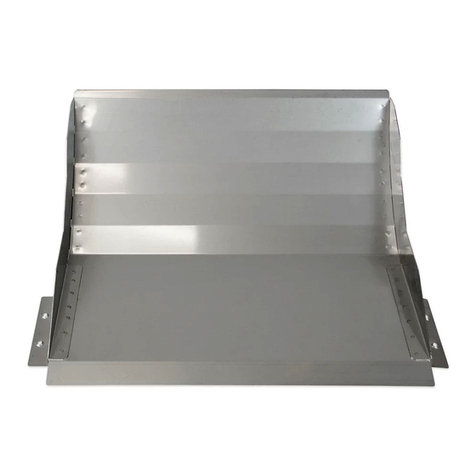
17 WALL MOUNT BRACKET
12 WIRING THE PRESTIGE TD
Do not run cable parallel to mains wiring
11 MOUNTING THE PRESTIGE TD
For indoor use only
10 COVERAGE PATTERN
Volumetric
9 COVERAGE AND PICK-UP
2
2 41 3
1 3 4 5
7
5
8
✗
Seal all holes
INS 253-3
See Mounting Height Diagram (Section 7)
6
✓
✓
15m
50’
15m
50’
85º
16 CEILING MOUNT BRACKET
✓
✗
✓
✗✓
Mount on a stable surface
230V
110V
230V
110V
✓
✗
13 CHOOSING A LOCATION
Avoid common false alarm sources
✗
✗
✗
✗
✗
✗
✗
✗
14 EOL RESISTOR JUMPER LINKS
The jumper links JP3 and JP4 (see Section 4) are used to select resistances for
End-of-Line (EOL) wiring applications.
If EOL wiring is not used, the headers should be left in the default (O/C) position.
If the required resistance values are not available, leave the headers in the O/C position
and wire in external resistors as normal.
EOL Settings for Texecom Panels JP3 JP4
Premier & Premier International 2k2 4k7Cexample
EXAMPLES OF EOL JUMPER LINK USE
JP3 Selects the End-of-Line
resistance. Equivalent to wiring
a resistor of the selected value
as shown.
JP4 Selects the resistance
across the alarm relay.
Equivalent to wiring a resistor
of the selected value as shown.
TAMPER - JP3 ALARM - JP4
Double Pole
(jumper links not used)
Dual End-of-Line
(DEOL)

Other Texecom Accessories manuals

Texecom Impaq S User manual

Texecom

Texecom Impaq S User manual

Texecom GFA-0001 User manual

Texecom

Texecom GFA-0001 User manual

Texecom Premier Elite Impaq Plus-W User manual

Texecom

Texecom Premier Elite Impaq Plus-W User manual

Texecom Medusa Service manual

Texecom

Texecom Medusa Service manual

Texecom Prestige External Series User manual

Texecom

Texecom Prestige External Series User manual

Texecom Mirage Dual Technology Service manual

Texecom

Texecom Mirage Dual Technology Service manual

Popular Accessories manuals by other brands

Manitowoc K00347 installation instructions

Manitowoc

Manitowoc K00347 installation instructions

Waterpik WP-360 quick start guide

Waterpik

Waterpik WP-360 quick start guide

Agilent Technologies U2000 Series Guide

Agilent Technologies

Agilent Technologies U2000 Series Guide

NEVADANANO MOLECULAR PROPERTY SPECTROMETER A2L Series user manual

NEVADANANO

NEVADANANO MOLECULAR PROPERTY SPECTROMETER A2L Series user manual

Balluff BAM PC-TL-020-K Series user guide

Balluff

Balluff BAM PC-TL-020-K Series user guide

SICK WTF16 operating instructions

SICK

SICK WTF16 operating instructions

PCB Piezotronics 102A02 Installation and operating manual

PCB Piezotronics

PCB Piezotronics 102A02 Installation and operating manual

SCENTED INTERIORS BY DESIGN PRO SCENT DIFFUSER User manual & installation guide

SCENTED INTERIORS BY DESIGN

SCENTED INTERIORS BY DESIGN PRO SCENT DIFFUSER User manual & installation guide

Enerwave ZWN-BDS installation instructions

Enerwave

Enerwave ZWN-BDS installation instructions

promethean ActivPanel Digital Pen user guide

promethean

promethean ActivPanel Digital Pen user guide

PCB Piezotronics ICP 261B02 manual

PCB Piezotronics

PCB Piezotronics ICP 261B02 manual

Omron LASER ZX - brochure

Omron

Omron LASER ZX - brochure

Acuity AR100 Super Compact Laser Sensor user manual

Acuity

Acuity AR100 Super Compact Laser Sensor user manual

HYTROL ABEZ Gen3 Installation and maintenance manual

HYTROL

HYTROL ABEZ Gen3 Installation and maintenance manual

Honeywell Ademco 5800SS1 installation guide

Honeywell

Honeywell Ademco 5800SS1 installation guide

Wenglor OY2TA104P0150P operating instructions

Wenglor

Wenglor OY2TA104P0150P operating instructions

Campbell 229 user manual

Campbell

Campbell 229 user manual

sparkfun TAS606 Getting started

sparkfun

sparkfun TAS606 Getting started

manuals.online logo
manuals.online logoBrands
  • About & Mission
  • Contact us
  • Privacy Policy
  • Terms and Conditions

Copyright 2025 Manuals.Online. All Rights Reserved.